Article

Application of Upgraded Drop-In Fuel Obtained from Biomass Pyrolysis in a Spark Ignition Engine

by
Alberto Veses
1,*,
Juan Daniel Martínez
2,
María Soledad Callén
1,
Ramón Murillo
1 and
Tomás García
1
1
Instituto de Carboquímica, ICB-CSIC, Miguel Luesma Castán 4, 50018 Zaragoza, Spain
2
Grupo de Investigaciones Ambientales (GIA), Universidad Pontificia Bolivariana, Circular 1 No. 74-50, Medellín 050031, Colombia
*
Author to whom correspondence should be addressed.
Energies 2020, 13(8), 2089; https://doi.org/10.3390/en13082089
Submission received: 26 March 2020 / Revised: 13 April 2020 / Accepted: 18 April 2020 / Published: 22 April 2020

Abstract

:
This paper reports the performance of a spark ignition engine using gasoline blended with an upgraded bio-oil rich in aromatics and ethanol. This upgraded bio-oil was obtained using a two-step catalytic process. The first step comprised an in-situ catalytic pyrolysis process with CaO in order to obtain a more stable deoxygenated organic fraction, while the second consisted of a catalytic cracking of the vapours released using ZSM-5 zeolites to obtain an aromatics-rich fraction. To facilitate the mixture between bio-oil and gasoline, ethanol was added. The behaviour of a stationary spark ignition engine G12TFH (9600 W) was described in terms of fuel consumption and electrical efficiency. In addition, gaseous emissions and polycyclic aromatic hydrocarbon (PAH) concentrations were determined. Trial tests suggested that it is possible to work with a blend of gasoline, ethanol and bio-oil (90/8/2 vol%, herein named G90E8B2) showing similar fuel consumption than pure gasoline (G100) at the same load. Moreover, combustion could be considered more efficient when small quantities of ethanol and organic bio-oil are simultaneously added. A reduction, not only in the PAH concentrations but also in the carcinogenic equivalent concentrations, was also obtained, decreasing the environmental impact of the exhaust gases. Thus, results show that it is technically feasible to use low blends of aroma-rich bio-oil, ethanol and gasoline in conventional spark ignition engines.

1. Introduction

Biomass pyrolysis produces solid, gas and liquid fractions. The first one, known as biochar, has several uses as a fuel, in soil remediation and even as a precursor of activated carbon, among others [1,2]. Both gases and liquids are also potentially renewable fuels and they can be used directly or mixed with traditional fuels in conventional internal combustion engines [3]. Pyrolysis gas can be easily used in energy generation, either in spark ignition or compression ignition engines. However, combustion parameters such as calorific value, flame velocity and ignition energy are key parameters regarding the feasibility of using such a low grade gaseous fuel [4]. Regarding to the liquid fraction, known as bio-oil, it still presents several challenges to be used directly to replace fossil fuels in conventional internal combustion engines. The presence of solid particles, high values of acidity, water content and viscosity, storage and thermal instability (due mainly to the presence of a wide range of oxygenated compounds [5]), low cetane number and low heating value prevent its direct application [6]. Thus, upgrading processes must be carried out to incorporate this product into existing infrastructure or to be used directly as drop-in fuel.
The use of bio-oils (both crude and upgraded), especially in compression ignition engines, has been reviewed, and the performance and exhaust emissions have already been studied [4,7,8]. In this sense, different experimental campaigns have reported several difficulties associated with the adverse properties of bio-oil. Mainly, these problems are related to the corrosion and clogging of the injectors, short combustion duration and long ignition delay, difficulties in engine start-up, unstable operation, coke deposition in the piston and cylinders, and subsequent engine seizure [4,9]. Similarly, some experiences show a preheating of the bio-oil prior to combustion. Likewise, costly and complex modifications of the engine can lead to improve the combustion conditions of bio-oil. Among others, these changes include special spark ignition systems for start-up, dual fuel systems, corrosion resistant injectors, and even an increase in the compression ratio [10].
Blending bio-oil with traditional fossil fuels is also an alternative method for utilising this renewable fuel in conventional combustion engines with nor or minor modifications. However, bio-oil blending with commercial fuels is not an easy task because bio-oil is not usually miscible with these fuels [11]. Even using emulsifying agents, stability problems often appear in the bio-oil/diesel blends leading to separation of phases [4]. Nevertheless, some experimental tests have been reported in the literature using bio-oil mixtures with biodiesel, ethanol and diesel fuels in compression ignition engines [9,10,12,13]. Van de Beld et al. [9] used a binary blend of ethanol (30 wt%) and bio-oil (70 wt%) in a modified one-cylinder diesel engine. For that, a stainless steel fuel injector was adapted to the engine. Surprisingly, the ethanol/bio-oil blend improved the overall engine performance, while CO emissions decreased and NOx emissions increased. However, the modification of the engine might be difficult to justify from an economic point of view. Hossain et al. [4] observed that 20 vol% of bio-oil obtained from de-inking sludge blended with 80 vol% biodiesel can be used in a multi-cylinder diesel engine without adding any ignition additives or surfactants. Although some solid deposits were observed inside the fuel filters, no deterioration in engine condition was observed after 3 h of operation. Pradhan et al. [12] found that the bio-oil from Mahua oilseed has high viscosity and low cetane number, and hence is not suitable for direct utilisation in a diesel engine. However, these authors reported that this bio-oil can be used blended in 30 vol% with diesel fuel in a single-cylinder diesel engine. Lee and Kim [14] examined the performance and emission characteristics of a modified diesel engine (dual-injection diesel engine) using a bio-oil-ethanol mixture. The pilot injection system ensured the proper combustion of high cetane number fuels developing those conditions to keep the main injection stable, which contained the bio-oil-ethanol blend. The results showed that although stable engine operation was possible, the engine efficiency should be improved. Additionally, hydrocarbons (HC) and CO emissions should be reduced.
Although most of the studies reported so far have been carried out using diesel-like fuels blended with bio-oil in compression ignition engines, the use of bio-oil in these engines still faces important challenges to reach a commercial level. On the other hand, the use of these bio-oils or any other kind of bio-fuel derived from them in spark ignition engines is rather rare in the literature. Latest advances in bio-oil upgrading have shown that it is possible to obtain an aroma-rich fraction [15,16]. This fraction has some of the main components of gasoline and could be considered a real additive for this fuel. In addition, upgraded bio-oil/ethanol blends could form a stable mixture without using surfactants or additives. The resulting viscosity is lower than that of pure bio-oil, improving not only atomisation conditions but also the storage and handling properties [17]. The application of a final mixed fuel comprised of gasoline, ethanol and upgraded bio-oil rich in aromatic compounds could emerge as a promising alternative to reduce the use of fossil fuels, while keeping the efficiency of the engine. In this line, the work carried out by Pelaez-Samaniego et al. [18] has shown promising results with a mixture of a fraction derived from a bio-oil obtained in the pyrolysis of sugarcane (rich in esters of carboxylic acids) with gasoline in a spark engine. Specifically, their results showed no significant differences in power and specific fuel consumption, concluding that it is technically feasible to use that mixture in a conventional Otto engine.
However, to the best of our knowledge, there have been no studies on the use of a direct drop-in fuel derived from an upgraded bio-oil in a spark ignition engine. Related studies found in the literature are mainly based on the use of the pyrolytic gas fraction [19]. Thus, successful application of upgraded drop-in fuel obtained from biomass pyrolysis in a spark ignition engine could have a positive impact on actual transportation fuel infrastructure. There are several important parameters, such as fuel consumption and electrical efficiency, that should be addressed to ensure technical feasibility. Moreover, exhaust emissions, including polycyclic aromatic hydrocarbons (PAHs) would provide not only useful information about combustion performance, but also a critical analysis of the air quality from the perspective of human health impacts.
In this work, the organic fraction obtained from a two-step catalytic process was blended in low proportions with commercial gasoline and ethanol. The resulting mixture was fed to a generator group (model G12TFH) equipped with Honda GX620 engine with a common-rail injection system. The main characteristics of the fuel were analysed, and important combustion parameters such as fuel consumption, electrical efficiency, gaseous emissions (O2, CO, CO2, CH4, C2H6, C2H4, C3H8, C3H6 and NOx,), and PAH concentrations were also determined.

2. Materials and Methods

2.1. Raw Bio-Oil

Bio-oil used in this work was obtained using a two-step catalytic process. The first step consisted of a catalytic pyrolysis using pine woodchips as feedstock and CaO as a catalyst. This step was carried out in an auger reactor at pilot scale at 450 °C and using N2 as carrier gas. Detailed information about experimental conditions and results can be found in previous works [20,21,22]. The second step also comprised a catalytic process, where the partial-deoxygenated organic fraction produced in the first step was heat-treated at 450 °C in a fixed-bed reactor with hierarchical ZSM-5 zeolite. More details about the catalytic cracking process and chemical characterisation of bio-oil can be found in previous research articles [23,24,25,26,27].

2.2. Gasoline and Ethanol

The gasoline used as commercial fuel reference and for blending was acquired from CEPSA Corporation (Spain). This fuel meets all the requirements established in the specifications defined by Royal Decree 1088/2010. It complies with Directive 2009/30/EC and with the European standard CEN EN 228. On the other hand, commercial ethanol (96 vol%) was provided by Scharlab, S.L.

2.3. Spark Ignition Engine and Generator

The experimental tests were carried out in a generator group (model G12TFH) equipped with an air-cooled, 4-Stroke, overhead valve (OHV), 90 L V-twin Honda GX620 engine with common-rail injection system. Specific characteristics of engine and generator can be seen in Table 1 and Table 2, respectively.

2.4. Characterisation of Organic Bio-Oil Fraction

The organic bio-oil fraction used in this work was analysed by determining different physicochemical properties according to different standard methods. Thus, ultimate composition (Carlo Erba EA1108) and calorific value (IKA C-2000) were determined according to UNE-EN ISO 16948:2015 [28] and UNE-EN ISO 18125:2018 [29], respectively. Water content was also determined by Karl-Fischer titration (Crison Titromatic) in accordance with ASTM E203-96 [30], while pH and total acid number (TAN) were determined at room temperature using a Mettler Toledo T50 device coupled with an electrode Inlab Micro and an electrode DGi118-solvant, respectively. Likewise, density (Antor-Paar DMA35N) and viscosity (Brookfield LVDV-E) were also measured following the standard ASTM D445 [31].
The chemical composition of the organic bio-oil fraction was determined by gas chromatography-mass spectrometry (GC/MS) by means of a Varian CP-3800 gas chromatograph (GC) coupled to a Saturn 2200 Ion Trap mass spectrometer (MS). A capillary column, CP-Sil 8 CB, low bleed: 5% phenyl, 95% dimethylpolysiloxane, (60 m, 0.25 mm i.d., film thickness 0.25 μm film thickness) was used. The oven temperature was initially set at 70 °C and then was kept there for 1 min. Then, a final column temperature of 300 °C was set, implementing a heating rate of 4 °C/min. From this point, the temperature was maintained for 21 min. He (BIP® quality) was used as the carrier gas was at a constant column flow rate of 1 mlN/min. 1 microliter of samples (1:25 wt%, solvent CH2Cl2:C2H6O (1:1)) was injected with a solvent delay of 7.5 min and a split ratio 25:1. The temperatures of the injector, detector and transfer line were 280 °C, 200 °C and 300 °C. Electron ionisation mode ranging between 35-550 m/z was used by MS, and compounds were determined by integrating the corresponding m/z. Duplicate analyses were carried out for each sample giving results as an average. At this point, it should be mentioned that relative standard deviation (RSD) values were lower than 10% for all components, and these low variations do not affect the discussion and conclusion sections. The percentage of each compound in the bio-oil was calculated by area normalisation, based on dividing the area of each peak between the total area. In this way, the compounds were classified into families according to their nature. The NIST2011 library was used to identify the mass spectra obtained from the GC/MS analyses.

2.5. Gas Emissions and Polycyclic Aromatic Hydrocarbons (PAHs) Trapping System

Gas emissions (O2, CO, CO2 and light hydrocarbons (CxHy)) were determined by gas chromatography. For this, several gas samples were analysed (every 5 minutes) in a Hewlett Packard series II GC connected to a Thermal Conductivity Detector (TCD). A Molsieve 5 Å column was used to analyse O2 and CO (isothermal at 60 °C) and a HayeSep Q column to analyse CO2 and CxHy (isothermal at 90 °C). In addition, a TESTO 350 XL analyser placed in the exhaust pipe of engine was used to carry out on-line characterisation of some of the gaseous emissions released (O2, CO2, NOx and SO2). It should be pointed out that the emissions always remained at similar values for all tests (RSD values lower than 7%–5% when gas % or ppm were measured).
A flow sampling system was also installed in the exhaust pipe to capture PAH emissions. The trapping system used for this purpose consisted of a quartz filter (47 mm diameter) to capture the PAHs present in the produced particulate matter and two connected steel tube cartridges filled up with XAD-2 resin (1.5 g each one) supported by quartz wool. The adsorption system was maintained at 120 °C, avoiding water condensation. Filters and resins were cleaned-up by Soxhlet extraction with DCM (24 h) before sampling.
PAHs were quantified using the GC/MS system previously described and following the methodology shown in a previous work [32]. Briefly, it consisted of individual Soxhlet extraction of the filter and each resin with the addition of deuterated-PAH surrogate standards containing different PAHs, such as anthracene-d10 (An-d10), acenaphthene-d10 (Ace-d10), benzo(a)anthracene-d12 (BaA-d12), benzo(ghi)-perylene-d12 (BghiP-d12) and benzo(a)pyrene-d12 (BaP-d12). Samples were concentrated by a rotary evaporator and afterwards by a nitrogen stream flow exchanging the solvent to n-hexane and p-terphenyl (p-tph) native was added as recovery standard.
Each compound was quantified by GC-MS/MS that operates at electron impact energy of 70 eV and utilising the multiple reaction monitoring (MRM) mode (S.1, PAH analysis). PAH quantification was conducted using the internal standard method that is in relation with the closest eluting PAH surrogate. Standard calibrations were prepared at different concentrations obtaining six-point calibration curves with correlation coefficients (r2) higher than 0.99. Injections were performed in the splitless mode using a selective PAH capillary column (0.25 mm inner diameter and 30 m length and with a film thickness of 0.25 µm). Helium BIP® at a constant flow of 1.5 mL/min was used as a carrier gas. The temperature/time program was 70 °C, 1 min until 325 °C with a ramp of 10 °C/min and this temperature was maintained for 13.5 min. The injector, ion trap and transfer line were kept at 280 °C, 200 °C and 300 °C, respectively.
The following PAHs were quantified by GC-MS/MS, according to their elution time: naphthalene (Np, m/z 102), acenaphthene (Ace, m/z 151), acenaphthylene (Acy, m/z 150), fluorene (Fl, m/z 163), fluoranthene (Fth, m/z 200), phenanthrene (Phe, m/z 152), anthracene (An, m/z 152), 2+2/4-methylphenanthrene (2+2/4MePhe, m/z 189), 9-methylphenanthrene (9MePhe, m/z 189), 1-methylphenanthrene (1MePhe, m/z 189), 2,5-/2,7-/4,5-dimethylphenanthrene (DiMePhe, m/z 191), pyrene (Py, m/z 200), benzo(b)fluoranthene (BbF, m/z 250), benzo(a)anthracene (BaA, m/z 226), chrysene (Chry, m/z 226), benzo(k)fluoranthene (BkF, m/z 250), benzo(a)pyrene (BaP, m/z 250), benzo(e)pyrene (BeP, m/z 250), indeno(1,2,3-cd)pyrene (IcdP, m/z 274), dibenzo(a,h)anthracene (DahA, m/z 276), benzo(ghi)perylene (BghiP, m/z 274) and coronene (Cor, m/z 298) [33]. Detailed information about the conditions for the PAH quantification by GC-MS/MS and PAH compounds and their toxic equivalency factors (TEF) was included in the supporting information (Tables S1 and S2).

2.6. Blending Step

The bio-oil organic fraction was first mixed with ethanol, maintaining a proportion of 20/80 in volume. This sample was kept for 1 day at 25 °C, showing no evidence of phase separation. The resulting mixture was then mixed with commercial gasoline (10/90 in volume) achieving a total mixture of 90/8/2 vol% of gasoline/ethanol/bio-oil. From this point, this sample will be referred to as G90E8B2. No higher proportions were able to be tested due to availability of the bio-oil sample. It should be noted that, based on the amount of available biomass for energy generation and, more concisely, based on the amount of bio-oil that can be generated by pyrolysis processes (which is low in comparison with fossil-based commercial fuels market) [34], this selected proportion is considered as representative to assess the influence of the biofuel as a drop-in fuel [4]. Moreover, it should be mentioned that new legislation concerning the promotion of the use of biofuels, as well as other renewable fuels in transport, proposes to reach higher percentages each year. Particularly, the European Directive 2009/28/EC [35], related to the promotion of the use of energy derived from renewable sources, establishes that each Member State shall guarantee that the share of energy derived from renewable sources concerning all types of transport in 2020 is at least equivalent to 10 percent of its final energy consumption in transport. Hence, considering that the ethanol is obtained from renewable sources, this mixture can be considered as a good approach to assess the results. The resulting sample was kept and filtered, ensuring no solid particles presence in the final mixture. Finally, in order to check the stability of the sample, it was stored for 1 day at 25 °C. After that period of time, no phase separation was observed and sample was considered ready to be used. An aliquot of the mixture can be seen in Figure 1.

2.7. Fuel Consumption and Electrical Efficiency

The fuel consumption is an important parameter to assess the performance of a fuel in an internal combustion engine. The assessment of this parameter estimates the potential fuel savings and costs, as well as reductions in CO2 emissions. Together with efficiency, this parameter gives a general perspective on how the engine works with a particular fuel. In this case, the electrical efficiency was calculated according to Equation (1) [13]:
Electrical   Efficiency   ( % ) = 100   ×   fuel   ×   ρ fuel ×   LHV fuel 3.6 × P e
where Øfuel corresponds with fuel consumption (l/h), ρfuel with the density (kg/L), LHVfuel with the lower heating value of each fuel (MJ/kg) and Pe with the electrical output (kW), being the same for the two tests (4.4 kW).

3. Results and Discussion

3.1. Properties of the Bio-Oil, Ethanol and Gasoline

Table 3 shows the main physicochemical characteristics of the upgraded bio-oil, the gasoline (G100), the ethanol (EtOH) and the resulting mixture of these fuels (G90E8B2). For comparison purposes, the same characterisations from common bio-oils were also included. Generally speaking, common bio-oils produced from biomass pyrolysis are characterised by a great amount of undesired oxygenated compounds. This composition and the remarkable water content (15–30 wt%), entails a polar nature that avoids a complete blending with commercial hydrocarbons. Moreover, the significant content of organic acids, such as acetic or formic acid, confers it a high acidic character (pH values around 2–3). Among other reasons, common pyrolysis oil presents poor ignition properties, complicating its use in common diesel or spark engines. A complete characterization of common pyrolysis oils can be found in extensive reviews [36]. On the other hand, the upgraded bio-oil used in this study shows interesting properties to be considered as potential drop-in fuel. Although there is still oxygen in the bio-oil, its content is much lower than that found in conventional bio-oils obtained from biomass pyrolysis [37,38]. This elemental composition entails a relative high calorific value (32.5 MJ/kg), which is a very important factor for the purpose of this work. In addition, acidic problems related to common bio-oils are expected to be reduced as higher pH and lower TAN values are observed. Also, it is important to highlight that water content is reduced with a final value lower than 5 wt%, keeping density and viscosity at the same values as those of common bio-oils. Regarding the mixture G90E8B2, it was observed that the proportions of ethanol and bio-oil used barely modified the main properties of the final fuel when compared to the initial gasoline sample. However, the applicability of a prospective bio-fuel can only be analysed by means of test engine runs [39]. For this reason, experiments in the engine were performed without any modification in comparison with the G100 experiment.
Regarding the chemical composition of common bio-oils, it can be stated that bio-oil is a complex organic mixture of compounds, mainly alcohols, ketones, phenols, aldehydes, ethers, esters, sugars, furans, alkenes, nitrogen and other different oxygenated compounds [40]. This liquid also presents considerable amount of reactive molecules with high molecular weight, that contribute to their instability [41]. Thus, upgrading post-conversion treatments are necessary to produce potential market bio-products [42,43]. Specifically, to facilitate the compatibility of bio-oil with other fuels, upgrading methods are focused on bio-oil deoxygenation and hydrogenation. Our research group has reached important advances in this field, achieving a great reduction of the oxygen content in the final bio-oil, as well as increasing the production of value-added products like aromatics. In this case, after the two-step upgrade process, it has been possible to obtain a significant deoxygenated organic phase rich in light aromatic compounds. These kinds of hydrocarbons make up a large part of gasoline, containing up to 35 vol%. Other hydrocarbons are olefins (18 vol%) and benzene (1 vol%) according to technical data files of CEPSA corporation [44]. It should be pointed out that the aromatic fraction of the upgraded bio-oil is mainly composed of C6–C8 aromatics (40–60 %). These components can be considered to be benzene, toluene and xylene (BTX) hydrocarbons, which are very valuable aromatic compounds. Thus, due to its properties and chemical composition, this liquid has been considered a potential renewable hydrocarbon biofuel able to be used as infrastructure-compatible fuel, i.e., as drop-in fuel. Detailed information about this process can be consulted in previous works [20,21,23,24].

3.2. Performance of Engine Tests

Experiments were conducted showing no operational problems and no difficulties in the start-up of the engine, which is one of the common problems when bio-oil is used as fuel in internal combustion engines [4,7]. It should be mentioned that, unfortunately, due to the availability of the bio-oil sample, it was only possible to check one mixture at one operational condition. However, for these conditions, the test was carried out over approximately one hour, showing no symptoms of malfunction. Hence, we consider that these results could be a very interesting starting point for future research, encouraging its application at a higher scale. Indeed, our research group has achieved recent advances in the field of drop-in fuels at higher scales [45], which could also have a great potential for this application. Interestingly, there is no remarkable differences in the specific fuel consumption when the G100 (0.74 g/kWh) and G90E8B2 (0.77 g/kWh) are used at the same load. This suggests that fuel mixture G90E8B2 could maintain the same power consumption as that of commercial gasoline, the small differences being related to the slightly lower calorific value of the mixed fuel [46]. These results are in line with those carried out by Pelaez-Samaniego et al. [18]. In that work, no significant differences in the fuel consumption were found when a bio-oil/gasoline blend (90/10 vol%) was used in a spark ignition engine. Likewise, the presence of ethanol in bio-oil has the advantage of improving viscosity and combustion conditions that seem to be favoured because of the higher octane number and higher flame speed compared to gasoline [47,48]. In addition, the electrical efficiency of the different fuels at the same load was found to be 9.72% and 9.99% for G100 and G90E8B2, respectively. Even so, it can be highlighted that overall efficiencies were very similar for both fuels but slightly superior for G90E8B2 sample.

3.3. Exhaust Gaseous Emissions

Figure 2 presents the gas emissions obtained from the GC analysis for O2, CO and CO2, for both fuels (G100 and G90E8B2) under steady state conditions. As it can be observed, oxygen amount in the exhaust gas is lower when the fuel mixture G90E8B2 is fed (16.5 g/kWh), as compared to that found for the G100 (42.0 g/kWh). This is directly related to the increase of CO2 emissions, which is higher for G90E8B2 (107.8 g/kWh) than for G100 (50.4 g/kWh). In addition, CO emissions were slightly lower for G90E8B2 (9.03 g/kWh) than for G100 (9.63 g/kWh). CO is a product of incomplete combustion, but it also depends on both the temperature in the cylinder and the oxygen content present in the fuel. Although it was not included for brevity and clarity, these tendencies of O2, CO and CO2 emissions at steady state could be verified by the results obtained using TESTO XL 350. O2, CO and CO2 emissions suggest a better combustion performance of the G90E8B2, mainly due to the fact that the oxygen content provided by both ethanol and bio-oil is higher. The availability of oxygen in G90E8B2 helps to reduce CO at expenses of CO2. Similar results have been reported in the literature. For instance, Deng et al. [49] observed in a four-cylinder spark ignition engine operated at different engine speeds that increasing ethanol concentration in a blend with gasoline lead to lower CO emissions than pure gasoline. Sakthivel et al. [50] also reported a decrease in the CO emissions with increasing ethanol content as compared to pure gasoline using a single-cylinder spark-ignition engine.
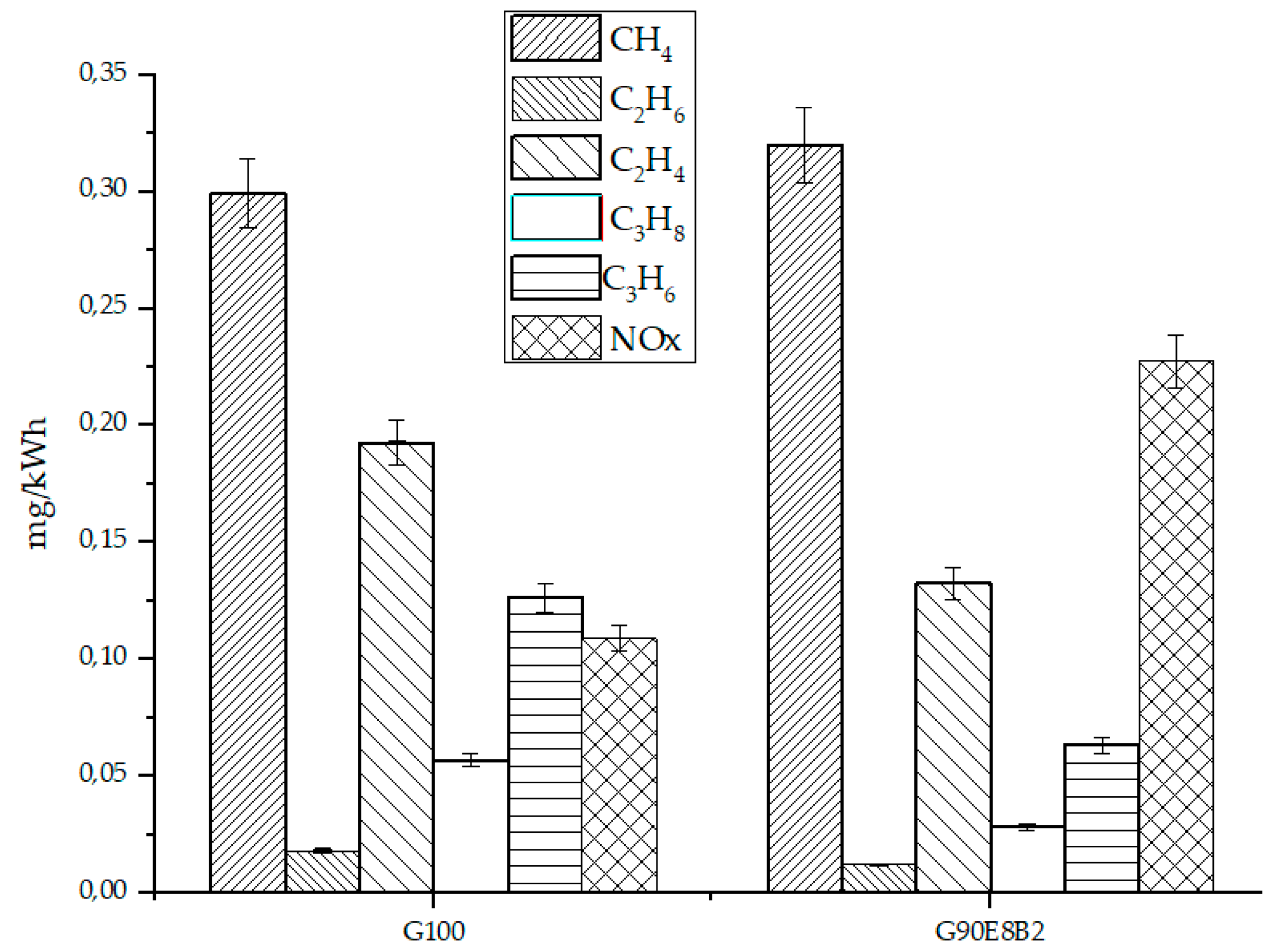
Another parameter that can provide some useful information about combustion efficiency is the amount of hydrocarbons (HC) emitted. Although differences are not very remarkable, the results shown in Figure 3 confirm that the total HC emissions were slightly higher when commercial gasoline was used instead of G90E8B2.
NOx emissions are another key parameter in assessing the environmental impact of any fuel used in an internal combustion engine. It is well known that thermal NOx generation mainly depends on temperature in the cylinder, the oxygen concentration in the combustion reaction, and the residence time. Ethanol has a higher latent heat and a lower energy density than gasoline, and hence a lower temperature is expected. However, as can be seen in Figure 3, NOx emissions (either NO and NO2) were higher when G90E8B2 (0.22 mg/kWh) was used, as compared to G-100 (0.11 mg/kWh). Deng et al. [49] also reported higher NOx emissions when the proportions of ethanol increased in a gasoline blend. This could be explained by the slightly higher nitrogen content accounted for the upgraded bio-oil (see Table 3). However, it cannot be completely ruled out that the increase in NOx emissions are directly related to the temperature and oxygen content in the combustion chamber, or even due to the higher water content of the mixture [12]. This fact could be also explained by the different value of the viscosity found for the mixture that could entail a different behaviour in the atomisation of the fuel in the cylinder [9]. It is also worth mentioning that SO2 was also evidenced, but only was significant in the first minutes of the experiment. While 3.44 mg/kWh were measured when G100 is tested, 0.68 mg/kWh were evidenced for the mixture G90E8B2. Although these can be considered small quantities, the fact of their incorporation in bio-oil can reduce environmental issues related to this component. This could be explained by the negligent sulphur content of the upgraded bio-oil fraction. If ethanol comes from renewable sources, its carbon footprint will be significantly reduced.

3.4. PAH Concentrations

Polycyclic aromatic hydrocarbons (PAH) can be produced because of the incomplete combustion of organic compounds. In any energy generation process, the identification and quantification of these compounds is very important owing to their carcinogenic and mutagenic effects with harmful impacts on human health [51]. This is one of the main reasons why 16 PAHs were recognised by the United States Environmental Protection Agency (US EPA) as a strong carcinogenic teratogenic PAH [52].
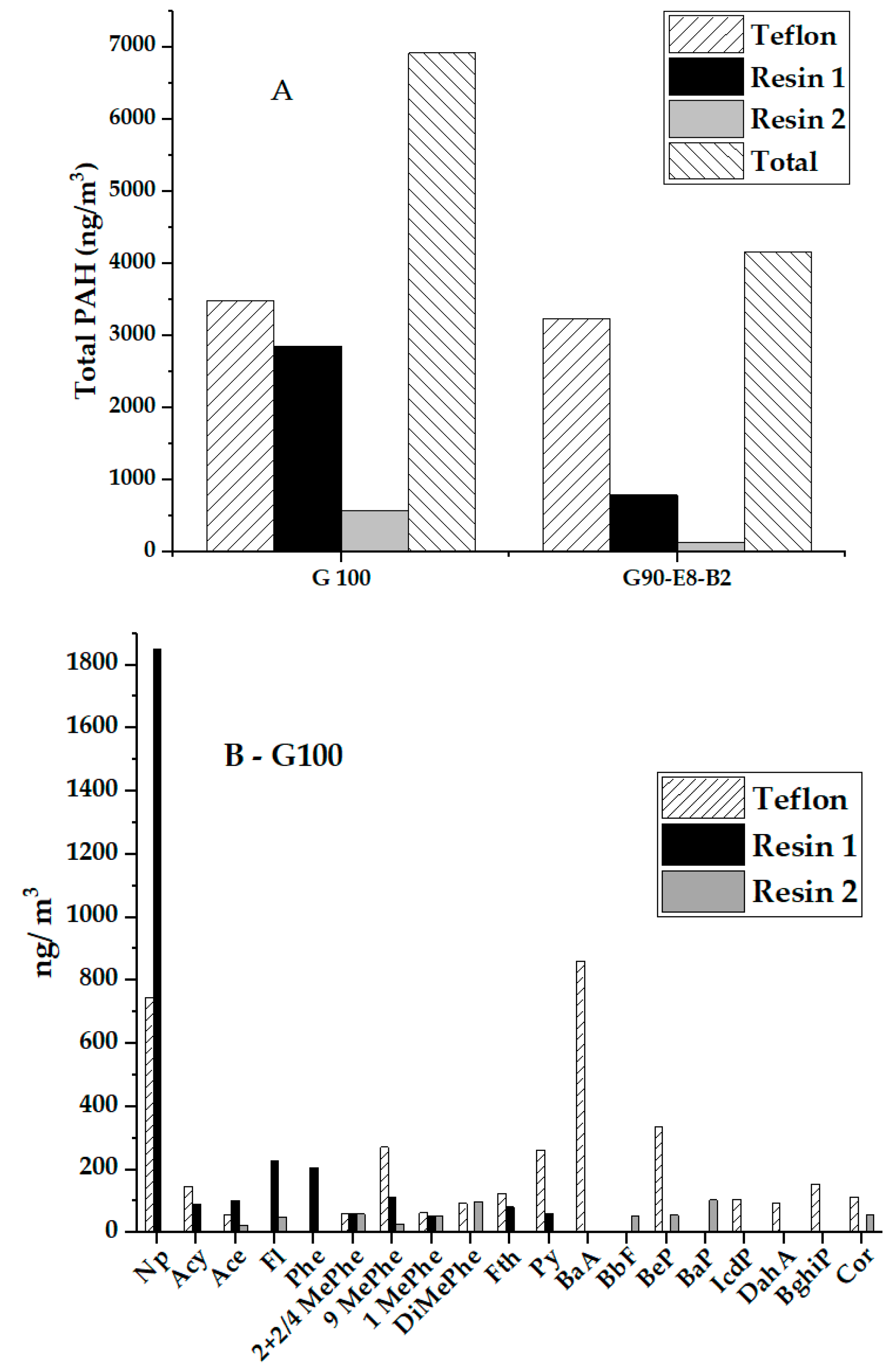
PAH concentrations for the two fuels (G100 and G90E8B2) were determined according to the sampling system; a Teflon filter and two simultaneous XAD®-2 resins (Figure 4). Each sample was injected by duplicate and relative standard deviation lower than 10% was obtained for each PAH, in each individual trap system. It was observed that the total PAH concentration was remarkably lower when using the G90E8B2 mixture (4164 ng/m3) than the one obtained working with G100 (6914 ng/m3). Moreover, this reduction was mainly appreciated in the resins system (gas phase PAHs). It is also important to highlight the distribution of PAHs according to their volatility as a function of the trapping system. In this regard, the resin was able to trap most of the volatile PAHs, whereas the Teflon filter retained a wider range of PAHs, including heavier PAH-like Cor. According to these results, it seems that the introduction of oxygen into the fuel provided by the ethanol and the upgraded bio-oil improved the efficiency of the combustion process, producing a smaller amount of PAHs, in particular the most volatile ones, which were mainly retained in both resins. These results were in accordance with the gas emission profile showed in the previous section, since oxygen values were lower for the G90E8B2. Other authors [53,54] already observed that oxygenated fuels decreased the soot precursor species during the fuel-rich premixed ignition and promoted the oxidation of the already-formed soot in a diffusion flame. Because certain unsaturated hydrocarbons, such as some PAH and acetylene, are the most likely precursors of soot particles [14], carbon atoms bonded to oxygen atoms in oxygenated fuels do not influence particulate matter formation, and this could explain the low PAH concentration from G90E8B2 combustion.
This could be also explained according to the nature of the fuel burnt. Authors like Yinhui et al. [55] found that higher concentration of aromatics in gasoline resulted in much higher particulate matter (PM) and PAH emissions. Reducing aromatic compounds content in gasoline by the addition of other fuel component, such as bio-oil/ethanol blend, could result as an important approach to reduce primary particulate emissions of gasoline vehicles and, in consequence, improve air quality [55]. Results found in this work corroborated the lower PAH concentration in G90E8B2 versus the G100 with the substitution of a fraction of gasoline by an ethanol/upgraded bio-oil blend.
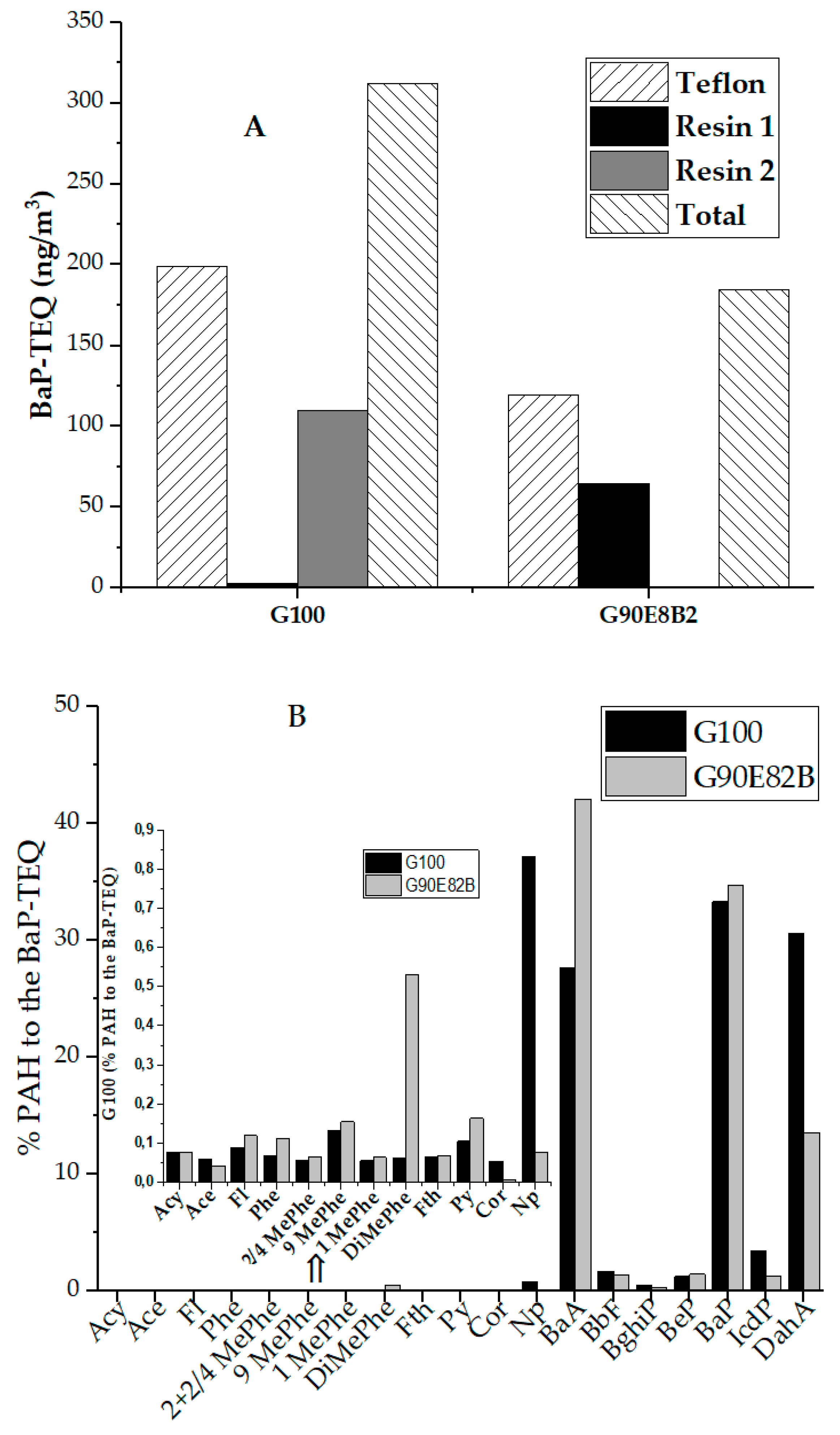
As mentioned above, PAH are listed as priority pollutants by the US EPA and they are released to the atmosphere after combustion processes. An interesting parameter to consider, in addition to PAH concentrations, is related to their carcinogenic character. One of the most carcinogenic PAHs is benzo(a)pyrene. In fact, this PAH is regulated by European directives (Directive 2004/107/EC [56]) setting a target value for PAHs in terms of concentration of BaP of 1.0 ng/m3 in the air as annual mean value measured in the particulate matter equal to or less than 10 µm (PM10) in aerodynamic diameter. In this way, an assessment of this character as a function of the different fuels based on toxic equivalency quotient (TEQ) relative to BaP (BaP-TEQ) was calculated. This behaviour was calculated by considering the toxic equivalency factors (TEF) of Nisbet and LaGoy (1992) [57] (Table S2) and multiplying the TEF by the concentration of each individual PAH in each sample. Results obtained for the two experiments were expressed as a function of the trapping system as BaP-TEQ (Figure 5A). It was observed that the fuel composed of the upgraded bio-oil presented a lower carcinogenicity factor than using pure gasoline. Despite some PAHs like DahA did not show a high contribution to the total PAHs, its contribution to the BaP-TEQ was remarkable, whereas other compounds like Np with high contribution in the G100 combustion were negligible in the BaP-TEQ concentration (Figure 5B). Independently of the fuel burnt, BaA, BaP and IcdP were the PAH with the maximum contribution to the BaP-TEQ. These results reflected the importance in studying PAH emissions, not only PAH concentrations but also the nature and the carcinogenic character of the individual PAH.
The promising results achieved in this work could offer the first insights on the potential application of upgraded bio-oil fraction as a drop-in fuel in current commercial engines. Extended duration tests and improving bio-oil properties, jointly with the study of different proportions in the final product, are the next steps to consider this application at higher scales.

4. Conclusions

In this work, an upgraded bio-oil/ethanol blend has been successfully tested as a drop-in fuel in a spark ignition engine. This renewable hydrocarbon biofuel can therefore be considered as an infrastructure-compatible fuel. Ethanol was added to facilitate the mixture and stability. The results revealed that it is possible to work with a blend 90/8/2 vol% of gasoline, ethanol and upgraded bio-oil fraction evidencing similar specific fuel consumption and electrical efficiency. Moreover, exhaust emissions suggest that combustion can be considered more completed. Likewise, this blend produces lower PAH concentrations than those with pure gasoline, mainly in the gas phase. Moreover, these emissions are less carcinogenic, which strongly improves the air quality from human health impact. Thus, the results showed that it is technically feasible to use low blends of aromatics-rich bio-oil and ethanol with gasoline in conventional spark engines.

Supplementary Materials

The following are available online at https://www.mdpi.com/1996-1073/13/8/2089/s1, S.1 PAH analysis, Table S1: Composition conditions for PAH quantification by GC-MS-MS, Table S2: PAH compounds and their toxic equivalency factors (TEF).

Author Contributions

Conceptualization, T.G. and R.M.; methodology, A.V.; validation, A.V. and J.D.M.; formal analysis; A.V., J.D.M. and M.S.C.; investigation, A.V., J.D.M., M.S.C.; resources, T.G. and R.M.; data curation, A.V., J.D.M. and M.S.C.; writing—original draft preparation, A.V., J.D.M. and M.S.C.; writing—review and editing, T.G. and R.M.; supervision, T.G. and M.S.C.; project administration, T.G. and M.S.C.; funding acquisition, T.G. and R.M. All authors have read and agreed to the published version of the manuscript.

Funding

This research was funded by MINECO and FEDER (Project ENE2015-68320-R) and the Regional Government of Aragon (DGA) under the research groups support programme.

Conflicts of Interest

The authors declare no conflict of interest.

References

  1. Yang, S.I.; Wu, M.S.; Wu, C.Y. Application of biomass fast pyrolysis part I: Pyrolysis characteristics and products. Energy 2014, 66, 162–171. [Google Scholar] [CrossRef]
  2. Peters, J.F.; Iribarren, D.; Dufour, J. Biomass Pyrolysis for Biochar or Energy Applications? A Life Cycle Assessment. Environ. Sci. Technol. 2015, 49, 5195–5202. [Google Scholar] [CrossRef] [PubMed]
  3. Mortensen, P.M.; Grunwaldt, J.D.; Jensen, P.A.; Knudsen, K.G.; Jensen, A.D. A review of catalytic upgrading of bio-oil to engine fuels. Appl. Catal. A Gen. 2011, 407, 1–19. [Google Scholar] [CrossRef]
  4. Hossain, A.K.; Davies, P.A. Pyrolysis liquids and gases as alternative fuels in internal combustion engines—A review. Renew. Sustain. Energy Rev. 2013, 21, 165–189. [Google Scholar] [CrossRef]
  5. Cheng, F.; Bayat, H.; Jena, U.; Brewer, C.E. Impact of feedstock composition on pyrolysis of low-cost, protein- and lignin-rich biomass: A review. J. Anal. Appl. Pyrolysis 2020, 147, 104780. [Google Scholar] [CrossRef]
  6. Fermoso, J.; Pizarro, P.; Coronado, J.M.; Serrano, D.P. Advanced biofuels production by upgrading of pyrolysis bio-oil. Wiley Interdiscip. Rev. Energy Environ. 2017, 6, e245. [Google Scholar] [CrossRef]
  7. Krutof, A.; Hawboldt, K. Blends of pyrolysis oil, petroleum, and other bio-based fuels: A review. Renew. Sustain. Energy Rev. 2016, 59, 406–419. [Google Scholar] [CrossRef]
  8. No, S.-Y. Application of bio-oils from lignocellulosic biomass to transportation, heat and power generation—A review. Renew. Sustain. Energy Rev. 2014, 40, 1108–1125. [Google Scholar] [CrossRef]
  9. Van de Beld, B.; Holle, E.; Florijn, J. The use of pyrolysis oil and pyrolysis oil derived fuels in diesel engines for CHP applications. Appl. Energy 2013, 102, 190–197. [Google Scholar] [CrossRef]
  10. Hossain, A.K.; Ouadi, M.; Siddiqui, S.U.; Yang, Y.; Brammer, J.; Hornung, A.; Kay, M.; Davies, P.A. Experimental investigation of performance, emission and combustion characteristics of an indirect injection multi-cylinder CI engine fuelled by blends of de-inking sludge pyrolysis oil with biodiesel. Fuel 2013, 105, 135–142. [Google Scholar] [CrossRef] [Green Version]
  11. Hansen, S.; Mirkouei, A.; Diaz, L.A. A comprehensive state-of-technology review for upgrading bio-oil to renewable or blended hydrocarbon fuels. Renew. Sustain. Energy Rev. 2020, 118, 109548. [Google Scholar] [CrossRef]
  12. Pradhan, D.; Bendu, H.; Singh, R.K.; Murugan, S. Mahua seed pyrolysis oil blends as an alternative fuel for light-duty diesel engines. Energy 2017, 118, 600–612. [Google Scholar] [CrossRef]
  13. Van de Beld, B.; Holle, E.; Florijn, J. The use of a fast pyrolysis oil—Ethanol blend in diesel engines for chp applications. Biomass Bioenergy 2018, 110, 114–122. [Google Scholar] [CrossRef]
  14. Lee, S.; Kim, T.Y. Feasibility study of using wood pyrolysis oil–ethanol blended fuel with diesel pilot injection in a diesel engine. Fuel 2015, 162, 65–73. [Google Scholar] [CrossRef]
  15. Rezaei, P.S.; Shafaghat, H.; Daud, W.M.A.W. Production of green aromatics and olefins by catalytic cracking of oxygenate compounds derived from biomass pyrolysis: A review. Appl. Catal. A Gen. 2014, 469, 490–511. [Google Scholar] [CrossRef]
  16. Rahman, M.M.; Liu, R.; Cai, J. Catalytic fast pyrolysis of biomass over zeolites for high quality bio-oil—A review. Fuel Process. Technol. 2018, 180, 32–46. [Google Scholar] [CrossRef]
  17. Nguyen, D.; Honnery, D. Combustion of bio-oil ethanol blends at elevated pressure. Fuel 2008, 87, 232–243. [Google Scholar] [CrossRef]
  18. Pelaez-Samaniego, M.R.; Mesa-Pérez, J.; Cortez, L.A.B.; Rocha, J.D.; Sanchez, C.G.; Marín, H. Use of blends of gasoline with biomass pyrolysis-oil derived fractions as fuels in an Otto engine. Energy Sustain. Dev. 2011, 15, 376–381. [Google Scholar] [CrossRef]
  19. Dupuis, D.P.; Grim, R.G.; Nelson, E.; Tan, E.C.D.; Ruddy, D.A.; Hernandez, S.; Westover, T.; Hensley, J.E.; Carpenter, D. High-Octane Gasoline from Biomass: Experimental, Economic, and Environmental Assessment. Appl. Energy 2019, 241, 25–33. [Google Scholar] [CrossRef]
  20. Veses, A.; Aznar, M.; Martínez, I.; Martínez, J.D.; López, J.M.; Navarro, M.V.; Callén, M.S.; Murillo, R.; García, T. Catalytic pyrolysis of wood biomass in an auger reactor using calcium-based catalysts. Bioresour. Technol. 2014, 162, 250–258. [Google Scholar] [CrossRef]
  21. Veses, A.; Aznar, M.; Callén, M.S.; Murillo, R.; García, T. An integrated process for the production of lignocellulosic biomass pyrolysis oils using calcined limestone as a heat carrier with catalytic properties. Fuel 2016, 181, 430–437. [Google Scholar] [CrossRef]
  22. Veses, A.; Aznar, M.; López, J.M.; Callén, M.S.; Murillo, R.; García, T. Production of upgraded bio-oils by biomass catalytic pyrolysis in an auger reactor using low cost materials. Fuel 2015, 141, 17–22. [Google Scholar] [CrossRef]
  23. Puértolas, B.; Veses, A.; Callén, M.S.; Mitchell, S.; García, T.; Pérez-Ramírez, J. Porosity-Acidity Interplay in Hierarchical ZSM-5 Zeolites for Pyrolysis Oil Valorization to Aromatics. ChemSusChem 2015, 8, 3283–3293. [Google Scholar] [CrossRef]
  24. Veses, A.; Puértolas, B.; López, J.M.; Callén, M.S.; Solsona, B.; García, T. Promoting Deoxygenation of Bio-Oil by Metal-Loaded Hierarchical ZSM-5 Zeolites. ACS Sustain. Chem. Eng. 2016, 4, 1653–1660. [Google Scholar] [CrossRef]
  25. Veses, A.; Puértolas, B.; Callén, M.S.; García, T. Catalytic upgrading of biomass derived pyrolysis vapors over metal-loaded ZSM-5 zeolites: Effect of different metal cations on the bio-oil final properties. Microporous Mesoporous Mater. 2015, 209, 189–196. [Google Scholar] [CrossRef]
  26. García, T.; Veses, A.; López, J.M.; Puértolas, B.; Pérez-Ramírez, J.; Callén, M.S. Determining Bio-Oil Composition via Chemometric Tools Based on Infrared Spectroscopy. ACS Sustain. Chem. Eng. 2017, 5, 8710–8719. [Google Scholar] [CrossRef]
  27. Veses, A.; López, J.M.; García, T.; Callén, M.S. Prediction of elemental composition, water content and heating value of upgraded biofuel from the catalytic cracking of pyrolysis bio-oil vapors by infrared spectroscopy and partial least square regression models. J. Anal. Appl. Pyrolysis 2018, 132, 102–110. [Google Scholar] [CrossRef] [Green Version]
  28. AENOR. UNE-EN ISO 16948:2015. Solid Biofuels-Determination of Total Content of Carbon, Hydrogen and Nitrogen; AENOR: Madrid, Spain, 2015. [Google Scholar]
  29. AENOR. UNE-EN ISO 18125:2018. Solid Biofuels-Determination of Calorific Value; AENOR: Madrid, Spain, 2018. [Google Scholar]
  30. ASTM. ASTM E203-96. Standard Test Method for Water Using Volumetric Karl Fischer Titration; ASTM International: West Conshohocken, PA, USA, 2016. [Google Scholar]
  31. ASTM. ASTM D445-19. Standard Test Method for Kinematic Viscosity of Transparent and Opaque Liquids (and Calculation of Dynamic Viscosity); ASTM International: West Conshohocken, PA, USA, 2019. [Google Scholar]
  32. Callén, M.S.; de la Cruz, M.T.; López, J.M.; Murillo, R.; Navarro, M.V.; Mastral, A.M. Some inferences on the mechanism of atmospheric gas/particle partitioning of polycyclic aromatic hydrocarbons (PAH) at Zaragoza (Spain). Chemosphere 2008, 73, 1357–1365. [Google Scholar] [CrossRef] [Green Version]
  33. Callén, M.S.; Iturmendi, A.; López, J.M. Source apportionment of atmospheric PM2.5-bound polycyclic aromatic hydrocarbons by a PMF receptor model. Assessment of potential risk for human health. Environ. Pollut. 2014, 195, 167–177. [Google Scholar] [CrossRef]
  34. Patel, M.; Zhang, X.; Kumar, A. Techno-economic and life cycle assessment on lignocellulosic biomass thermochemical conversion technologies: A review. Renew. Sustain. Energy Rev. 2016, 53, 1486–1499. [Google Scholar] [CrossRef]
  35. European Commission. Directive 2009/28/EC of the European Parliament and of the Council of 23 April 2009 on the promotion of the use of energy from renewable sources. Off. J. Eur. Union 2009, L140, 16–62. [Google Scholar]
  36. Oasmaa, A.; Peacocke, C. A Guide to Physical Property Characterisation of Biomass-Derived Fast Pyrolysis Liquids; VTT Publications; Technical Research Centre of Finland: Espoo, Finland, 2010; pp. 2–65. [Google Scholar]
  37. Chiaramonti, D.; Oasmaa, A.; Solantausta, Y. Power generation using fast pyrolysis liquids from biomass. Renew. Sustain. Energy Rev. 2007, 11, 1056–1086. [Google Scholar] [CrossRef]
  38. Meier, D.; Van De Beld, B.; Bridgwater, A.V.; Elliott, D.C.; Oasmaa, A.; Preto, F. State-of-the-art of fast pyrolysis in IEA bioenergy member countries. Renew. Sustain. Energy Rev. 2013, 20, 619–641. [Google Scholar] [CrossRef]
  39. Harnisch, F.; Blei, I.; dos Santos, T.R.; Möller, M.; Nilges, P.; Eilts, P.; Schröder, U. From the test-tube to the test-engine: Assessing the suitability of prospective liquid biofuel compounds. RSC Adv. 2013, 3, 9594–9605. [Google Scholar] [CrossRef]
  40. Hu, X.; Gholizadeh, M. Biomass pyrolysis: A review of the process development and challenges from initial researches up to the commercialisation stage. J. Energy Chem. 2019, 39, 109–143. [Google Scholar] [CrossRef] [Green Version]
  41. Garcìa-Pérez, M.; Chaala, A.; Pakdel, H.; Kretschmer, D.; Rodrigue, D.; Roy, C. Multiphase Structure of Bio-oils. Energy Fuels 2006, 20, 364–375. [Google Scholar] [CrossRef]
  42. Makarfi Isa, Y.; Ganda, E.T. Bio-oil as a potential source of petroleum range fuels. Renew. Sustain. Energy Rev. 2018, 81, 69–75. [Google Scholar] [CrossRef]
  43. Oh, Y.-K.; Hwang, K.-R.; Kim, C.; Kim, J.R.; Lee, J.-S. Recent developments and key barriers to advanced biofuels: A short review. Bioresour. Technol. 2018, 257, 320–333. [Google Scholar] [CrossRef]
  44. Cepsa Global Energy Company Home Page. Available online: http://www.cepsa.com (accessed on 24 March 2020).
  45. Sanahuja-Parejo, O.; Veses, A.; López, J.M.; Murillo, R.; Callén, M.S.; García, T. Ca-based Catalysts for the Production of High-Quality Bio-Oils from the Catalytic Co-Pyrolysis of Grape Seeds and Waste Tyres. Catalysts 2019, 9, 992. [Google Scholar] [CrossRef] [Green Version]
  46. Martínez, J.D.; Rodríguez-Fernández, J.; Sánchez-Valdepeñas, J.; Murillo, R.; García, T. Performance and emissions of an automotive diesel engine using a tire pyrolysis liquid blend. Fuel 2014, 115, 490–499. [Google Scholar] [CrossRef]
  47. Bergthorson, J.M.; Thomson, M.J. A review of the combustion and emissions properties of advanced transportation biofuels and their impact on existing and future engines. Renew. Sustain. Energy Rev. 2015, 42, 1393–1417. [Google Scholar] [CrossRef]
  48. Zhang, Z.; Wang, T.; Jia, M.; Wei, Q.; Meng, X.; Shu, G. Combustion and particle number emissions of a direct injection spark ignition engine operating on ethanol/gasoline and n-butanol/gasoline blends with exhaust gas recirculation. Fuel 2014, 130, 177–188. [Google Scholar] [CrossRef]
  49. Deng, X.; Chen, Z.; Wang, X.; Zhen, H.; Xie, R. Exhaust noise, performance and emission characteristics of spark ignition engine fuelled with pure gasoline and hydrous ethanol gasoline blends. Case Stud. Therm. Eng. 2018, 12, 55–63. [Google Scholar] [CrossRef]
  50. Sakthivel, P.; Subramanian, K.A.; Mathai, R. Experimental study on unregulated emission characteristics of a two-wheeler with ethanol-gasoline blends (E0 to E50). Fuel 2020, 262, 116504. [Google Scholar] [CrossRef]
  51. World Health Organization. Environmental health criteria 229: Nitrogenated polycyclic aromatic hydrocarbons. In WHO Report Number. International Program on Chemical Safety; WHO, Ed.; World Health Organization: Geneva, Switzerland, 2004. [Google Scholar]
  52. [ATSDR] Agency for Toxic Substances and Disease Registry. Toxicological Profile for Polycyclic Aromatic Hydrocarbons (PAHs) (Update); US Department of Health and Human Services: Atlanta, GA, USA, 1995.
  53. Song, J.; Cheenkachorn, K.; Wang, J.; Perez, J.; Boehman, A.L.; Young, P.J.; Waller, F.J. Effect of Oxygenated Fuel on Combustion and Emissions in a Light-Duty Turbo Diesel Engine. Energy Fuels 2002, 16, 294–301. [Google Scholar] [CrossRef]
  54. Westbrook, C.K.; Pitz, W.J.; Curran, H.J. Chemical Kinetic Modeling Study of the Effects of Oxygenated Hydrocarbons on Soot Emissions from Diesel Engines. J. Phys. Chem. A 2006, 110, 6912–6922. [Google Scholar] [CrossRef] [Green Version]
  55. Yinhui, W.; Rong, Z.; Yanhong, Q.; Jianfei, P.; Mengren, L.; Jianrong, L.; Yusheng, W.; Min, H.; Shijin, S. The impact of fuel compositions on the particulate emissions of direct injection gasoline engine. Fuel 2016, 166, 543–552. [Google Scholar] [CrossRef]
  56. European Commission. Directive 2004/107/EC of the European Parliament and of the Council of 15 December 2004 relating to arsenic, cadmium, mercury, nickel and polycyclic aromatic hydrocarbons in ambient air. Off. J. Eur. Union 2004, L23, 3–16. [Google Scholar]
  57. Nisbet, I.C.T.; LaGoy, P.K. Toxic equivalency factors (TEFs) for polycyclic aromatic hydrocarbons (PAHs). Regul. Toxicol. Pharmacol. 1992, 16, 290–300. [Google Scholar] [CrossRef]
Figure 1. Final sample of G90E8B2 after filtering.
Energies 13 02089 g001
Figure 2. O2, CO and CO2 emissions at steady state obtained from the gas chromatograph (GC) analysis.
Energies 13 02089 g002
Figure 3. Hydrocarbon and NOx emissions at steady state obtained from the GC analysis.
Energies 13 02089 g003
Figure 4. (A): Polycyclic aromatic hydrocarbon (PAH) concentrations for each fuel as a function of the trap system. (B,C): Distribution of PAH according to their volatility as a function of the trapping system.
Energies 13 02089 g004aEnergies 13 02089 g004b
Figure 5. (A): Benzo(a)pyrene (BaP)-TEQ (ng/m3) as a function of the fuel for each individual trap systems. (B): percentage of contribution of each individual PAH to the BaP-TEQ for each fuel.
Energies 13 02089 g005
Table 1. Main specifications of the spark ignition engine.
Engine TypeAir-Cooled, 4-Stroke, OHV, 90 L V-twin
Bore × Stroke77 × 66 mm
Displacement614 cm3
Compression Ratio8.3:1
Net Power Output13.5 kW at 3600 rpm
Net Torque40.6 Nm at 2500 rpm
Number of cylinders2
Nominal fuel consumption4.1 L/h
Dimensions (L × W × H)388 × 457 × 452 mm
Net Weight42 kg
Table 2. Main specifications of the generator group.
Start TypeElectric, Automatic
Number of phases3 (380/220 V/V)
Type of generatorSynchronic
Active power9.6 kW
Total power12 kVA
Noise level77 dB
Dimensions (L × W × H)900 × 600 × 580 mm
Weight107 kg
Table 3. Some properties of common crude bio-oils (adapted from [8]), organic bio-oil fraction used in this work, gasoline, ethanol and G90E8B2 blend.
FuelUltimate Analysis (%.wt)Calorific Value (MJ/kg)Water Content (%.wt)pH–25 °CTAN (mgKOH/g)Viscosity (cP)–40 °CDensity (kg/L)–25 °C
COHNS
Crude bio-oils30–4035–556–70.2–0.50.016–1715–302–360–9010–151.1–1.4
Upgraded bio-oil7516.48.40.20.032.54.74.021.39.41.15
G10087.20.012.90.00.0143.6<0.12.9<50.120.75
EtOH52.234.713.10.00.029.63.87.3<51.90.78
G90E8B284.23.112.80.0040.00942.30.43.2<50.450.77