Abstract
Models of technical systems are an essential means in design and product-development processes. A large share of technical systems, or at least subsystems, are directly or indirectly connected with the generation or transformation of energies. In design science, elaborated modelling approaches were developed for different levels of product concretization, for instance, requirement models and function models, which support innovation and new product-development processes, as well as for energy-generating or -transforming systems. However, on one product-concretization level, the abstract level that describes the physical behavior, research is less mature, and an overview of the approaches, their respective advantages, and the connection possibilities between them and other modelling forms is difficult to achieve. This paper proposes a novel discussion structure based on modelling perspectives and digital-engineering frameworks. In this structure, current approaches are described and illustrated on the basis of an example of a technical system, a wind turbine. The approaches were compared, and their specific advantages were elaborated. It is a central conclusion that all perspectives could contribute to holistic product modelling. Consequently, combination and integration possibilities were discussed as well. Another contribution is the derivation of future research directions in this field; these were derived both from the identification of “white spots” and the most promising modelling approaches.
1. Introduction
Today, the general consensus is that the early stages of product development are essential [1,2,3]. Changes in advanced stages can be avoided through systematic and structured procedure schemes, and through the application of efficient methods and tools that aim at raising the knowledge of the system at the beginning of development to a higher level [4]. However, a widely accepted methodology with computational support for these stages, which is applied in industrial practice, does not yet exist [1]. Consequently, design and control engineers are challenged with undocumented considerations and decisions, incompatible modelling languages, unclear and incomplete interfaces, redundant work, and non-value-adding data-transformation activities. This leads, on the one hand, to product-development processes that lack efficiency, and, on the other hand, to suboptimal solutions for technical systems to be developed. Today, the early stages of requirement management [5,6] and function modelling [7,8] are well-researched, but this research that is concerning the modelling possibilities on an intermediate level is much less mature, which links these two description modes to concrete product geometry, material, and structure. A general need for a description of abstract physics was identified in 1965 by Atkin [9]. Research presented in this paper is based on the hypothesis that an efficient and effective approach for modelling the physical behavior of technical systems on an abstract level could help engineers to synthesize innovative, reliable, and safe solutions. The respective research question is formulated in the next subsection.
1.1. Research-Question Development
The general consensus in design science is that the description levels of function, behavior, and structure can be distinguished [10]. As stated above, powerful methods and tools are available today that allow a holistic digital description on the functional [7] and structural level. However, on the intermediate level of behavior, no holistic digital approach has arrived in industrial practice. It is very important for engineers to be familiar with the behavior and physical cause–effect thinking, and to know properties and possible applications of physical phenomena since the central functions of most technical systems are physically realized [11]. During the last few decades, several models, methods, and tools were proposed that address this important level. Some of these concentrate on the rather qualitative exploration and synthesis of chains of physical phenomena, others on quantitative simulations of behavior (analytical, logical, statistical, and numerical), and others on interfaces between function carriers. Relatively few research activities are concentrated on a combination of the perspectives and the integration of industrial companies in digital processes, and the results have not yet been applied in industrial practice. This leads to the central research question of this paper: what the current status is of modelling approaches and engineering frameworks that allow to capture physical-phenomenon chains, behavior simulation, control design, and interfaces between function carriers, as well as to connect those to product and process structures, and to integrate them in digital product-development processes.
1.2. Scientfic Contribution
The unique contribution of this paper from a scientific point of view is the collection, evaluation, and comparison of ontologies and modelling techniques that enable improved and integrated analysis, and synthesis on the layer that describes the abstract physical realization of functions of a technical system. All modelling perspectives and engineering frameworks are explained on the basis of a common example, a wind turbine. The aim was not the development of a conclusive answer on in which manner with which models the abstract physical behavior of technical systems should be modelled for enabling efficient and effective system-development processes, and efficient, effective, safe, and reliable production and operation of these technical systems. The unique contribution is in-depth analysis of languages, modelling approaches, and frameworks, and identification of their specific merits and limitations. This analysis led to an overview of existing approaches, and resulted in a summary of perspectives and important aspects. Analysis results explain integration necessities and approaches, and consequently present a structure and promising areas for future research.
1.3. Paper Structure
The paper is structured as follows: Section 2 provides a background on abstract physics. Section 3 concentrates on different modelling perspectives on this level of product concretization. The integration of these perspectives in an engineering framework are the topic of Section 4. Section 5 formulates desirable future research activities and concludes the paper.
2. Abstract Physics—Background
For many decades, design science has developed abstract product models and a distinction of product models on the basis of their level of abstraction (compare with Ehrlenspiel and Meerkamm [11], Lindemann [12], Pahl et al. [13], Ponn and Lindemann [14]); today, a four-level distinction is generally agreed upon (sometimes the most abstract level, requirements, is not explicitly included, but its existence is not challenged). The four-level distinction is illustrated in Figure 1.
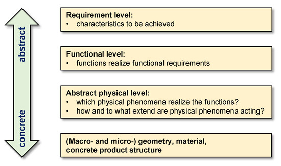
Figure 1.
Four-level distinction of product concretization.
The requirements, i.e., the characteristics of the product needed to fulfil the demands of all stakeholders (most prominently, the customers) form the top level. It is often emphasized that an occupation with requirements is inevitable throughout any product-development process [14]; a thorough clarification and negotiation of the requirements in the early stages is one of the main cornerstones of product-development success [3]. More concrete is the functional level, because it is analyzed and synthesized on this level of which functions in what structure are able to realize the functional requirements. Both the requirement level and the function level were integrated in the last few years in digital-engineering frameworks [6,8]. The actual (macro- and micro-) geometry, material, and product structure are described on the most concrete level. Additionally, concrete control concepts, fault-detection systems, reliability, and safety considerations primarily concern this level. The gap between this very concrete level and the rather abstract functional level can be filled with an intermediate level that consists of physical phenomena or effects and their combinations that realize the functions; the network of these physical phenomena leads to the physical behavior of the technical system. Another aspect, especially in the field of process and chemical engineering, is chemical effects that can also be essential for technical systems (especially matter-oriented technical systems) but are not in the focus of this paper. Analysis of the current literature led to the conclusion that increasing scientific interest can analyze, reflect, understand, and support analysis and synthesis of physical-effect chains and networks that may realize required functions in the domain of physics and physical behavior. This analysis also leads to the insight that more than one perspective is required in order to allow a holistic model of abstract physics. Figure 2 illustrates the possible perspectives.
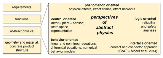
Figure 2.
Abstract-physics perspectives.
In the literature, five different perspectives of abstract physics can be identified: a phenomenon-oriented perspective that contains physical effects, chains, and networks; a behavior-oriented perspective that contains linear and nonlinear equations, differential equations, and numerical behavior models; an interface-oriented perspective that describes physical contacts and connectors; a logic-oriented perspective, primarily used for reliability and safety analyses; and a control-oriented perspective, employing actor–plant sensor models and state-space representations. An explanation and discussion of abstract-physical-modelling approaches that are based on these perspectives is the content of the next section.
3. Modelling Perspectives of Abstract Physics
For analysis and synthesis of abstract physics, five perspectives can be found in the literature and clearly distinguished: phenomenon-, a behavior-, logic-, control-, and interface-oriented perspectives.
3.1. Phenomenon-Oriented Perspective
Several years ago, design science proposed the consideration of abstract physics in the form of the physical effects (elementary demarcated physical phenomena) and effect chains or networks that are composed of the elementary physical phenomena. In this context, physical effects are understood as elementary definable physical phenomena that can be described on the basis of conservation laws (mass, energy, linear momentum, and angular momentum-conservation law) and equilibrium laws (force and moment equilibrium) by means of their relationships with each other [11]. The occupation with physical effects is recommended for fostering a better and deeper understanding of technical systems and for developing innovative solutions that use different physical principles [11]. Engineers need to be familiar with the main physical cause-and-effect chains of the product under development. Engineers should know the application possibilities of physical effects, and their limitations. An additional positive effect of this occupation with the physical background is that a solution search with physical effects can dissolve mental blocks [11]. Stetter and Niedermeier [15] analyzed innovative breakthrough products and concluded that such products in most cases rely on different physical principles. In the same direction, Wulf [16] formulated the insight that a discursive, hierarchical search for solutions that includes the level functions and physical structure probably leads to good design.
Analysis and synthesis of physical structures using physical effects can be explained using the example of a wind turbine. A very important subfunction is “change speed”, which means to increase the angular velocity from the rotor shaft to the generator because generators with a higher angular velocity can be smaller and more efficient. Two possible physical effects to realize this subfunction are shown in the lower part of Figure 3.
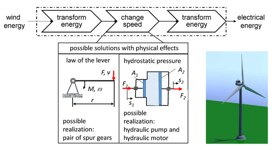
Figure 3.
Function structure of wind turbine and possible physical effects for function “change speed”.
Both of the presented physical effects can lead to an increase of speed. Despite the fact that nearly all wind turbines rely on the law of the lever with spur or planetary gears, solutions with hydraulic pumps and motors or hybrid transmissions are also being investigated [17,18]. Obviously, the choice of the optimal physical effect and the synthesis of the physical structure strongly depend on the specific requirements of the given application case.
Nearly a decade ago, analysis of physical effects was expanded in order to include uncertainties in the form of disturbances [19]. It is possible to define robustness ratios of the physical effects on the basis of known disturbances, and one may evaluate and compare different solution possibilities of a subfunction concerning their respective robustness. In the area of computational design synthesis (CDS), Helms [20] realized an integration of phenomenon-oriented abstract physics in the form of physical effects by creating a method to automate the transfer of formerly paper-based engineering knowledge about physical effects into a computable representation.
Lang [4] developed the idea to reduce technical systems to such an extent that physical effects were as isolated as possible and could be empirically analyzed under clearly defined conditions. He found that analysis and understanding of physical effects can be a decisive factor for principal investigations. According to Lang [4], these investigations can be empirical analyses in the early phases of a product-development process that are intended to quantitatively describe physical phenomena. It is a central characteristic of such principal investigations that real processes are reduced to isolated physical principles or effects. On the same level of abstraction is the contribution of Wagner [21], who described a synthesis process including physical effects for the realization of function integration in technical systems.
For all complex technical systems, more than one physical effect is needed, and the physical effects need to be combined to physical-effect chains or networks (a network, in contrast to a chain, allows, among others, feedback loops that are possible in physical systems). A physical-effect chain describing the blade pitch-angle-adjustment system of a wind turbine is shown in Figure 4 (phenomenon-oriented perspective).
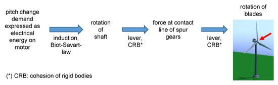
Figure 4.
Physical-effect chain for electrical-blade pitch-angle adjustment.
Input is an intended change of the blade pitch angle that is expressed in the form of electrical energy on the blade pitch-adjustment motor. The physical effects of induction and the Biot–Savart law in this motor lead to the rotation of a short shaft that holds a small spur gear. The physical effects of the lever and the cohesion of rigid bodies (only one rigid body can be at a certain position at a certain time, and two rigid bodies do not permeate each other) lead to contact force at the contact line with a second, much larger spur gear. This spur gear is connected to the blades and leads to a rotational movement of the blades around the longitudinal axis—a change of the pitch angle. Again, the physical effects of the lever and the cohesion of rigid bodies are employed. Such chains and networks can be transformed into an initial description of the behavioral perspective (Figure 5), which includes a mathematical description, and may be used for simulation and optimization purposes.
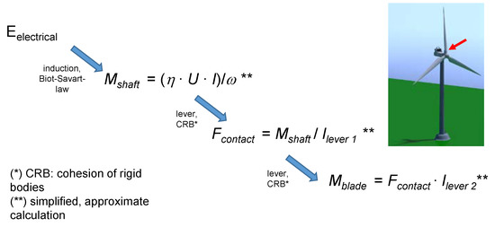
Figure 5.
Physical-effect chain with simplified mathematical description.
This kind of model leads to the next section, which discusses the behavior-oriented perspective. To conclude, modelling approaches that are based on the phenomenon-oriented perspective are demarcated physical phenomena that are combined to affect chains or networks. The main advantage of their application is supporting a deeper understanding of the technical system, and the potential for breakthrough innovation if the main physical effects of a technical system are altered.
3.2. Behavior-Oriented Perspective
Abstract physical behavior is also the main emphasis of the intermediate level of function–behavior–structure (FBS) ontology [10], which is essentially a design ontology that can describe designed artefacts. FBS consists of three fundamental constructs, function (F), behavior (B), and structure (S). The construct function represents the objective of the artefact (for what the artefact is). The construct behavior describes the attributes of the artefact, which are either derived from its structure (what the artefact does) or expected behavior (what the artefact should do). The definition of this construct in the literature does not include notions such as operation, process, or physical effects; the explanations and examples clearly indicate that this kind of concept could also be appropriate to describe phenomena on this abstraction level. The last construct structure stands for the components of a technical system and their relationships (of what the artefact consists); this construct clearly corresponds to the concrete realization of the technical system.
Generally, the intended level of abstraction can be understood as a level describing the physical behavior of a technical system, i.e., its intended or actual performance for realizing certain functions. Many physical phenomena can be described by means of analytic equations (linear and nonlinear equations); however, abstraction and simplification from actual physical behavior are usually necessary. For instance, the circumferential speed of the rotor of a wind turbine can be derived from the number of revolutions in a certain time interval using the following equation.
where vc stands for circumferential speed, r for rotor radius, and nr for the number of revolutions in a certain time interval. In an engineering context, frequently differential or partial differential equations are used, such as the governing differential equation of motion for the transverse vibration of the tower of a wind turbine [22,23].
where ρ stands for air density, A for cross-sectional area of the tower, η is the transverse displacement coordinate, y the vertical coordinate measured from the tower base, E the Young’s modulus of the tower, I the second moment of area of the tower, and f is a function describing the wave and wind load. In current engineering practice, numerical modelling and analysis techniques are very often employed. Current examples concern the simulation of wind turbines with hydraulic transmission systems [24], of wind-turbine-blade vibration [25], of the drive train of a wind turbine [26], and of the aeroelastic behavior of wind-turbine blades [27]. In this research area, Chu et al. [28] performed comparative analysis of appropriate identification methods concerning the mechanical dynamics of wind turbines. In the area of research concerning the planning and operation of power systems, Li et al. [29] proposed a planning model and a new objective function for maximizing the accommodation of renewable energy, and provided an extensive literature review in this research area. Needless to say, due to the enormous importance of wind turbines in the scope of renewable-energy generation, numerous further research activities could be identified. Besides the large number of research directions, powerful possibilities for behavior modelling already exist; prominent examples are finite-element analysis (FEA) and analysis of multibody systems (MBS). Usually, these possibilities require concrete geometrical and physical parameters. Topology optimization systems [30] also incorporate certain kinds of physical-behavior modelling to synthesize optimized structures. Important examples for behavior modelling are also Modelica or MATLAB/Simulink (The MathWorks, Natick, Massachusetts, MA, USA); several commercial software products enable behavioral descriptions of technical systems that are based on Modelica (e.g., Dymola (Dassault Systèmes, Vélizy-Villacoublay, France), Simcenter Amesim (Siemens PLM Software, Plano, Texas, USA, MapleSim (Maplesoft, Waterloo, Ontario, Canada), Wolfram SystemModeler (Wolfram Research, Champaign, Illinois, USA), Modelon (Modelon AB, Lund, Sweden) and SimulationX (ESI ITI GmbH, Dresden, Germany). These tools allow the development of complex simulation models (compare with, e.g., Fritzson [31]). Despite their convincing performance and versatility, these simulation systems do not provide holistic links to the requirements and functions of a technical system, and require concrete geometrical and physical parameters. An advanced solution for the integration between graph-based languages and behavior modelling in the form of continuous mechanics was proposed by Vogel [32]; main emphasis was also on concrete geometry and advanced analyses of this geometry. An initial modelling approach for effect chains on the behavior level was proposed by Chamas and Paetzold [1].
In the field of computational-design synthesis (CDS), approaches to connect requirements, functions, structural parameters, and behavioral-performance evaluation have already been proposed. These approaches are based on bond-graph-based simulation models for performance evaluations on the behavioral level [33]; they are discussed in detail in Section 4.2.
We can be concluded that a behavior-oriented perspective on abstract physics that allows analytical and numerical simulation and optimization plays an enormous role in research and industrial practices. This perspective can also be connected to the early approach towards describing abstract physics by Atkin [9].
3.3. Interface-Oriented Perspective
On a similar level of abstraction, the research group of Albers proposed the contact and connector approach (C&C2–A). This approach allows analysis of interfaces and physical structures within technical systems [34,35]. An example, for the ball contact in the main bearing of a wind turbine, is shown in Figure 6.
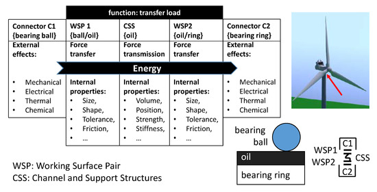
Figure 6.
Example for contact and connector (C&C2) model based on ball contact of main bearing.
In C&C2 models, the effect network is composed of the following fundamental modelling elements [34]:
- working surface pairs (WSP) that stand for interfaces between physical structures;
- channel and support structures (CSS) that permanently or occasionally represent interacting physical structures of solid bodies, liquids, gases, or fields; and
- connectors (C), which model elements that denote the effect and state properties of the environment that is relevant for the function of a system.
Figure 6 depicts force flow (described as energy because, in many flow-oriented function models, only matter, energy, and information flows are distinguished) from the bearing ball through a layer of oil or grease to the bearing ring. For all entities in this chain, internal properties can be listed, as well as external effects for the connectors to the environment. In this approach, an effect network is described that stores, transforms, and exchanges inputs and outputs that may be energy, material, and information flows. However, the inclusion and description of demarcated physical phenomena are not explicitly addressed. The distinctive advantage of this perspective is that it allows detailed analyses of effect surfaces and interactions that are not included in the other perspectives.
3.4. Logic-Oriented Perspective
Due to the complexity of modern technical systems, it is a major challenge to ensure their reliability. In order to estimate the reliability of a complex system, an accurate reliability model of the system needs to be developed [36]. Gausemeier et al. [37] emphasized that the information provided by the abstract physical solution is useful for supporting procedures for analyzing the reliability of systems to be developed. Complex technical systems require reliability-analysis methods and tools that can be applied in the early engineering phase of conceptual design in order to enable the detection of failures at an early stage, and to avoid time-consuming and costly iteration loops [38]. Models used in safety analysis (compare with [39,40]) are, in general, similar to the ones applied for reliability analysis. Very often, the models for these two areas describe logical relationships because nearly all systems dispose of redundant elements, of which the influence on safety and reliability needs to be explored in a logical manner. The reliability of wind turbines is a major issue because maintenance and replacement activities are time-consuming and can even be dangerous. The logical-modelling perspective is explained using a rather simple system, a redundant wind sensor. The common modelling approach is a logical fault tree that represents a superordinate system with its subsystems. This tree can connect the fault possibilities of the subsystems or components to the fault possibility of the superordinate system. A fault tree with main connection elements AND and OR is shown in Figure 7 (left).
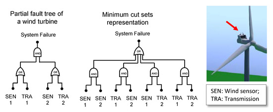
Figure 7.
Example of partial fault tree of wind turbine and a minimal cut-set representation.
In the literature, numerous possibilities for the generation and analysis of fault trees can be found [36]. An initial analysis step is the generation of a minimal cut set, shown in Figure 7 (middle). Here, the fault tree was converted into minimal-cut-set representation. Cut sets can be understood as unique combinations of subsystem or component failures that can cause the failure of the superordinate system [41]. A minimal cut set is achieved if, when any basic event is removed from the set, the remaining events are collectively no longer a cut set [42]. The scope of the given example is the wind sensors (SEN) themselves and all elements that are necessary for transmission (TRA) from the sensor to the central control unit that controls the angle of the wind turbine. For correct operation of the superordinate system, that is, the wind-information subsystem of the wind turbine, it is required that at least one subsystem (wind sensor with its transmission system) is working properly, and that, within this system, both wind sensor and transmission are functional. Such interactions of system elements can be shown in a logical fault tree and then analyzed in multiple ways, e.g., for reliability modelling [43] and redundancy analysis [44,45].
A similar intention is followed by research aiming at exploring undesired functions of principle solutions, which may be fault causes [46]. Current research concerns the stochastic [45] or data-driven [36] generation of reliability models because current systems include hardware and software with complex interactions that are becoming increasingly difficult to model. Further research activities explore the reliability of interdependent networks with cascading failures [47], load-sharing failure-based reliability analysis for parallel systems [48], and frameworks for analyzing and modelling the failure behavior of cognitive products in the conceptual design phase [49].
To conclude, the logical perspective offers distinct advantages and a unique view on the technical system, not only on which physical phenomena the system should perform, but also which it will perform in the case of unintended behavior of subsystems and components.
3.5. Control-Oriented Perspective
Today, nearly all technical systems dispose of control systems that are, in general, based on some sensing of the systems and some corrective activity. In control engineering, it was found advantageous to describe theses control elements; commonly, a system perspective is employed that distinguishes actuators, the process itself, sensors, and controller(s). In recent times, additional entities were added that allowed fault accommodation: a fault-diagnosis block, analytic redundancy (based on mathematical models of the process, the actuator(s), and/or sensor(s)), and elements that allow the redesign of the controller in the case of a fault. This kind of modern control-system model is shown using the example of a wind turbine in Figure 8; compare with [41,50].
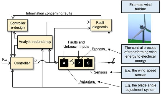
Figure 8.
Control-oriented perspective on a technical system (example: wind turbine) with modern control system.
On the basis of understanding the system, system behavior is frequently modeled using state-space representation, which is the mathematical model of a technical system represented as a set of input, output, and state variables usually related by first-order differential equations. The values of so-called state variables evolve over time. They serve as variables on the axes of the state space, and the state is represented as a vector in this space. Three general kinds of state-space descriptions can be distinguished: continuous time, discrete time, and discrete event.
In continuous time, the state of a system can, for instance, be described with the following set of equations.
where x is the state vector, is its time derivative dx/dt, y is the measurement vector, u is the input vector, fa denotes the actuator fault vector, fs denotes the sensor fault vector, w1,2 stand for disturbance vectors, A is the state matrix, B is the input matrix, C is the output matrix, Cf is the output matrix for sensor faults, and W1,2 denote disturbance-distribution matrices. For a wind turbine, a state vector based on a reduced-order model (compare with [51]) may be formulated for certain kinds of generators as
where ω stands for the angular velocity of the generator (this is usually proportional to the angular velocity of the wind turbine), udc for DC-link voltage, and β for the pitch angle. Control input vector u may consist of reference signals, such as reference blade pitch angle βref. Actuator faults, such as a jammed-blade pitch-angle-adjustment system, are expressed in actuator fault vector fa, and sensor faults (such as a wind-speed sensor deviation caused, e.g., by friction) are expressed in sensor-fault vector fs. When transferred to discrete time (often done for simulation purposes using certain discretization techniques such as Euler discretization), the following set of equations form the system description.
For many systems, such as production systems, it is sensible to model not instances of time, but events such as the arrival of a preproduction part at a manufacturing station. An exemplary system description for a discrete-event system would be
In recent years, another aspect was added to the control perspective, the inclusion of remaining useful life (RUL). A knowledge of RUL of certain (redundant) system elements allows control algorithms that decrease the load on these elements, and thus prolong the operation time of the superordinate system. In order to do so, an additional step can be added to the well-known steps of diagnostics, as shown in Figure 9.
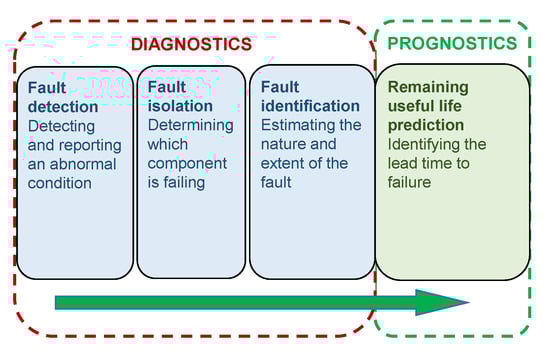
Figure 9.
Prognostic step added to diagnostic steps.
Steps in the diagnostics phase in Figure 9 are carried out in the fault-diagnosis block in Figure 8. Fault diagnosis is a three-step process: detecting an abnormal condition, continuing with the determination of the failing component(s), and concluding with an estimation of the nature and extent of the fault. The central objective of the prognostics phase in Figure 9 is the prognosis of the phenomenon of physical degradation. Typical degradation behavior (compare with [41]) is shown in Figure 10.
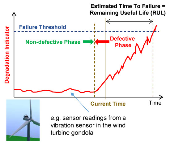
Figure 10.
Typical physical-degradation behavior.
Obviously, typical degradation behavior as shown in Figure 10 can also be understood as a physical-behavior model because, during degradation in a defective phase, physical behavior changes. Ultimately, the prognosis step aims at the prediction of the health of a product (compare with [52,53]). For this prediction, it is possible to process information describing prior use, current state, and past, present, and future environmental conditions. The enormous importance of degradation processes has led to numerous research efforts. These efforts aim at predicting the remaining useful life (RUL) or, synonymously, the estimated time to failure (ETTF), and at developing approaches that determine if technical systems exhibit clear indicators for degradation. In this research, clear distinction is proposed between a fault (a deviation of a property from the usual condition [54] without serious consequences, such as system shut-down) and a failure (a catastrophic event [50]). In many cases, it is possible to derive failure thresholds from a system’s functional requirements [6] or from models of product functions [55].
A further research area relying on the control-oriented perspective concerns the fault tolerance of technical systems. In complex and networked technical systems, errors can never be completely avoided, so the lack of fault tolerance can lead to enormous losses, so the development of effective methods to increase fault tolerance is an essential and challenging research topic [56]. In the application field of turbines, several research groups aim at increasing fault tolerance. For instance, Habibi et al. [57] proposed an adaptive fault-tolerant neural-based control design considering unknown wind speeds.
The control-oriented perspective offers insights and possibilities that other perspective cannot. The control-oriented perspective enables and supports the control of technical systems itself, stability analyses, controller design, the accommodation of faults, and many similar tasks. Current expansions of this perspective also include changed physical behavior caused by degradation; obviously, this topic is connected with the reliability and safety aspects of the logical perspective, but integrated modelling approaches are still to be developed. The control-oriented perspective is gaining importance in the age of ubiquitous computing—even relatively small subsystems can sense their environment, adapt their behavior, communicate with other subsystems and, through this, contribute to system-spanning planning and control endeavors, as well as systemwide fault detection and identification. The inclusion of RUL aspects allows planning and control activities that prolong the system functionality of a supersystem, e.g., if it is possible to reduce the load on already degrading subsystems.
3.6. Summary
Concluding Section 3, which investigated five different perspectives of abstract physics, all of the perspectives have their unique merits and offer information content that is not present in the models of other perspectives. The perspectives are compared in Table 1.

Table 1.
Overview of modelling perspectives.
A holistic-model-based engineering framework needs to include elements of all five perspectives, and existing approaches that aim at integrating the models may lead to this framework; these are discussed in the subsequent section.
4. Integration of Perspectives
Holistic development processes of technical systems require the introduction of high-level integrated design methods, and early design phases, such as conceptual design and system modelling, play important roles [58]. Consequently, the integration of several perspectives of abstract physics is desirable. Several research activities address this challenge, and a conscious selection is investigated in this section.
4.1. Expansion of Integrated-Function-Modelling Framework
The main focus of the integrated-function-modelling (IFM) framework is on more abstract-level function [7]. Holistic functional analysis of systems or subsystems is enabled through this framework; an example from a wind turbine is the subsystem that adjusts the pitch angle of the blades, and it is shown in Figure 11.
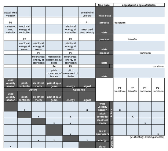
Figure 11.
Function model of blade pitch-angle adjustment (modified integrated-function-modelling (IFM) framework).
In the state view (upper-left corner of Figure 11), it can be seen that actual wind velocity is transformed to measured wind velocity that could be processed by the pitch controller. This controller transfers electrical energy to the electrical motor for blade pitch-angle adjustment if the controller determines that wind speed makes a change of the pitch angle desirable. The electrical motor transforms electrical to mechanical energy at a set of spur gears (motor and set of spur gears are present at each blade). The pair of spur gears transform the incoming mechanical energy (rather low torque, but higher speed) to mechanical energy that can change the blade pitch angle (rather high torque, but lower speed). Other elements of the IFM are the interaction view (lower-left corner Figure 11), the actor view (lower-right corner Figure 11), and the process-flow view (upper-right corner Figure 11). It is obvious that the connection of functions and flows of operand energy and signal are clarified in this model. This framework already considers effects that can be applied in order to realize functions [7], i.e., the IFM includes the so-called effect view (Figure 12).
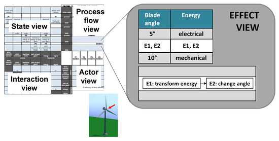
Figure 12.
Effect view in IFM for the subfunction “adjust blade-pitch angle”.
The effects in the view shown in Figure 12 are defined as representations of physiochemical effects or principles that are necessary for enabling or supporting the execution of transformation and/or interaction processes [7]. In a large-scale study investigating the industrial applicability of the IFM framework, contents of the effect view (physiochemical effects; effects related to different processes) were considered useful by more than half of the participants [7]. The distinctive quality of the IFM is the connection of several views (four functional views and one physical view) and the established industrial acceptance. It is obvious that the present effect view is not satisfactory to fulfill modelling necessities identified in Section 3. However, the link to a holistic functional structure makes a connection of future modelling approaches of abstract physics to the IFM highly desirable.
4.2. Integration in Computational-Design Synthesis Framework
For decades, many industrial companies have pursued the goal of automating their design processes to accelerate them, reduce design costs, and allow individual user designs. In many cases, a high level of automation can already be realized, especially for routine design and for modular products, which may be automatically configured according to specific requirements (compare with [59]). In spite of existing applications, computational support for the abstract initial phases of design and product-development processes is rare [60]. A major research direction can be summarized under the notion of knowledge-based engineering (KBE); the main intention is the automation and streamlining of routine/repetitive design tasks mainly occurring in the later design stages [61]; usually, the main physical phenomena are already determined in these phases, and the merit for perspectives concerning abstract physics is relatively small. Another main research direction is computational-design synthesis (CDS), main intention of which being the support of the early stages of design processes, and large and often unstructured solutions are explored [61]. CDS is researched since several years (a good overview of earlier approaches can be found in [62]). A far-reaching approach in the area of CDS was reported by Wölkl and Shea [63], who developed a computational product model in system modelling language (SysML, based on unified modelling language) for conceptual design, which also included abstract physics. For behavior modelling, four diagrams of SysML can, in general, be employed: the activity, sequence, state-machine, and use-case diagrams. These diagrams, together with other important diagrams of SysML (compare with [63]), are shown in Figure 13.
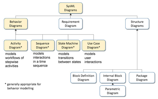
Figure 13.
Possibilities for behavior modelling in the system modelling language (SysML).
Wölkl and Shea [63] emphasized the general applicability of SysML for conceptual design stages including abstract physics. The main emphasis was on non-geometric information. Further research activities in this field showed possibilities to include a phenomenon-oriented perspective (compare with [20]). Helms [20] was able to develop a scheme that allows a systematic, automatic search for appropriate physical effects (Figure 14).
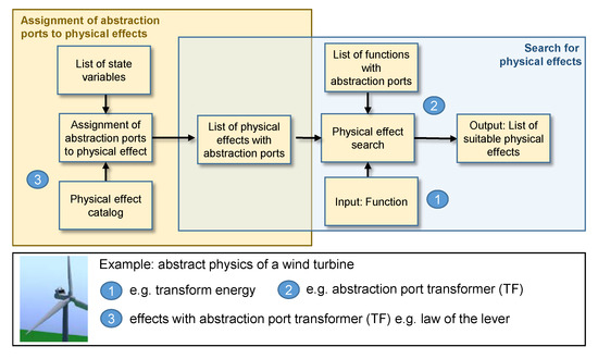
Figure 14.
Scheme for automatic search for appropriate physical effects.
The scheme shown in Figure 14 is based on so-called abstraction ports. These ports were proposed because the current lack of reuse of design knowledge is, among others, caused by the heterogeneity of numerous knowledge sources and calls for the development of means that makes it possible to systematically express and classify physical effects at a uniform layer of abstraction [20]. This means could bridge the gap between function and behavior, and would enable standardization. The concept of abstraction ports provides uniform classification, thus allowing for the search of physical-effect catalogs. Current research activities still integrate some aspects of abstract physics and physical behavior [64]; these activities were successfully applied for the creation of multiple solution alternatives of hybrid-car concepts [65]. Current work also concerns network-based analysis of transition graphs; a novel approach was proposed for analyzing grammar rules by means of combining graph representation (transition graph) of generated designs and rule applications with network-analysis algorithms and interactive visualizations [66]. Currently, research is being carried out that aims at estimating the impact of design automation [60,61,67,68].
In the CDS field, a rich body for design automation that is also in the early stages can be found. Most proposed approaches include some aspects of physical behavior; in-depth investigation of the possible perspectives on this level is frequently not the main emphasis. Further research is needed for implementing developed approaches that aim at supporting engineers to consciously choose appropriate physical effects, and to design effect chains. The design of effect networks that are connected to other models in product-development processes also needs further scientific emphasis.
4.3. Integration in Frameworks Based on Graph-Based Design Languages
In recent years, an engineering framework based on graph-based design languages (GBDL) was developed in close co-operation with industrial companies. This engineering framework addresses the challenge that current product development processes are characterized by a multiplicity of different domains; the consequence are immense efforts for exchanging data and information between these domains. Current research activities were able to show that it is possible to use a common language to describe the product and processes throughout the product lifecycle, for instance, a graph-based design language based on the unified modelling language (UML). Graph-based design languages for engineering design and product development were first proposed by Rudolph [69]. Examples of the application of graph-based languages include power poles [70], satellite systems [71], gear systems for suburban trains [6], quadcopters and multicopters [55], balanced two-wheel scooters [72], automotive dashboards [73], exhaust systems [32], car bodies [74], and automated guided vehicles [41]. The application of this kind of rule-based systems leads to a central data model in the form of a design graph (compiled from the UML model - compare with [75]) with interfaces to all domains in the product lifecycle (Figure 15).
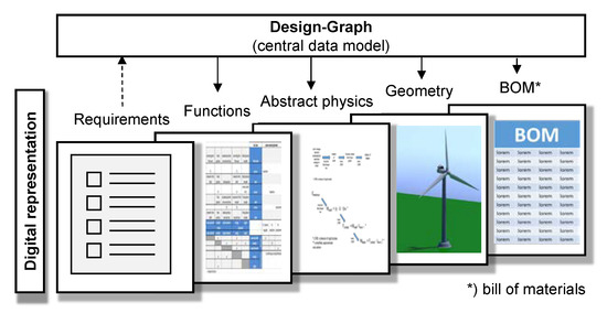
Figure 15.
Central data model and different domains in product lifecycle.
A main advantage of the application of graph-based design languages is the resulting inherent consistency of the generated graph because all different domains receive their information from this data model. Computer software that is able to compile a graph-based design language is the so-called Design Compiler 43 [76]. This design compiler was developed by IILS GmbH, Trochtelfingen, Germany, in co-operation with the University of Stuttgart, and it has the unique capability to synthesize detailed and complex geometry models from UML diagrams. From the design graph, the central data model, different kinds of models can be generated, such as requirement (e.g., conventional lists or ReqIf models (ReqIF is an XML file format for the documentation and exchange of requirements), function (e.g., modelled in the IFM, Section 4.1), simplified-abstract-physics (compare with [77]), and geometry models, and a “bill of materials” (BOM). The digital product-development process on the basis of graph-based design languages with UML is sketched in Figure 16 (compare with [55] and [78]).
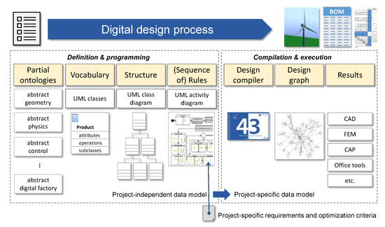
Figure 16.
Digital design process based on graph-based design languages.
The digital design process based on graph-based design languages starts with so-called partial ontologies that serve as the basis for the creation of a language usually describing a family of possible products. An ontology is a formal description of the concepts and relationships that exist for a certain area of knowledge or application, and it defines the basic terms, concepts, and relations comprising the vocabulary of a domain [79]; for example, the partial ontology of abstract geometry defines the basic geometrical terms (such as cylinder), concepts (such as intersection), and relations (such as positioned at the border) in the domain of industrial-system development. Partial ontologies need to capture the engineering knowledge of the involved domains; terms, concepts, and relations that are not defined in a partial ontology cannot be used in the system language, and cannot be expressed in the resulting model perspectives and models of the technical system. Many research works do not explicitly include the investigation of ontologies; however, implicitly, they are part of any system modelling endeavor and any modelling perspective. Research activities are also connected that aim at metamodels, i.e., abstract models that describe the organization and structure of the product and process models to be created (compare [80]).
On the basis of partial ontologies, responsible engineers are able to program the vocabulary (expressed in UML classes for product entities such as product components), structure (expressed in UML class diagrams—the structure of product entities), and rules (expressed as UML activity diagrams–model transformations) for a whole product family or spectrum. The resulting project independent-data model is then objected to project-specific requirements and optimization criteria, and an automated compilation and execution process is carried out. The result of the compilation is a design graph; all kinds of domain-specific proprietary-data formats can be created from this design graph. First, scientific attempts to integrate abstract physics into digital product design using design languages are currently investigated [77]. An existing design language for functional modelling was extended to include abstract physics; the resulting class diagram is shown in Figure 17 (compare with [77]).
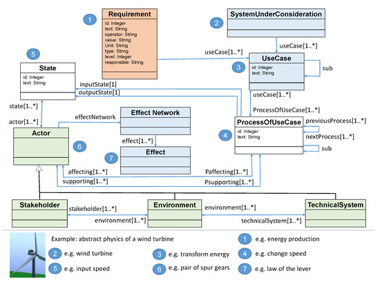
Figure 17.
Possible class diagram of integrated design language.
So far, this expansion was explained using one example, the steering system of a balanced two-wheel scooter. The expansion includes the integration of three aspects of abstract physics (phenomenon-, behavior-, and interface-oriented) in a digital engineering framework. The presented framework potentially has the ability to compile numerous instances of information formulated in UML, and to synthesize a design graph with interconnected geometrical, physical, and structural information. A further strength is the integration in the product life cycle. Still, a comparison with perspectives explained in Section 3 makes it obvious that further research is needed for integrating all necessary perspectives and aspects concerning the modelling of abstract physics. Additionally, some aspects concerning the vertical integration in cyber–physical systems and their development are not yet covered; these are investigated in the subsequent section.
4.4. Integration in Frameworks for Cyber–Physical-System Development
The integration of data, information, and models is the main emphasis of research activities concerning the development of cyber–physical systems (CPSs). A cyber–physical system can be defined as a physical system in which operations are monitored, co-ordinated, controlled, and integrated by a communication and computation system [81]; they may be understood as mechatronic systems with both horizontal multidomain integration within one organization and vertical integration between subsystem suppliers and the suppliers of complete systems (compare with [58]). A CPS produces physical and virtual processes, and their integration in all phases of a system-development process and consistent system modelling are major challenges (Figure 18); (compare with [58]).
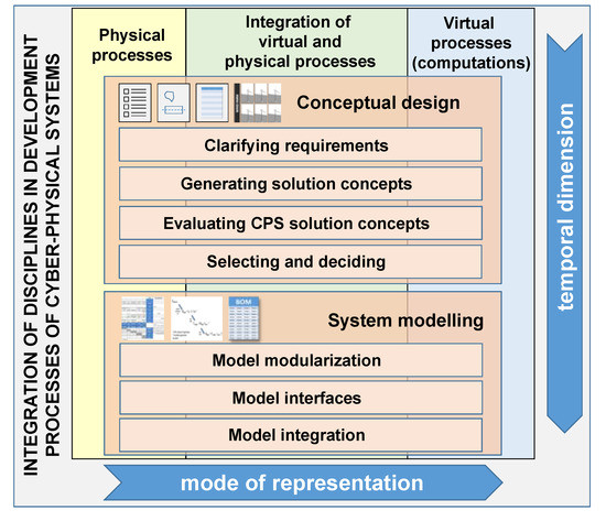
Figure 18.
Integration of disciplines during an early design process of cyber–physical systems (CPSs).
The effective and efficient development of CPSs requires the application of abstract integrated design methods and models that allow engineers to simultaneously consider all aspects of a multidomain system. The physical behavior of a CPS is controlled by virtual processes; this circumstance has to be considered both during conceptual design and system modelling (Figure 18). Several tools, models, and methods are proposed for addressing this issue, e.g., the use of UML and SysML (compare with [82,83,84]). Frequently, Modelica is applied for behavior modelling because models created in Modelica can be transferred into mathematical models that allow detailed simulations [58]. Modelica is a freely available, object-oriented modelling language that was specifically developed for the modelling of heterogeneous systems, and was applied in many cases for the connection of virtual and physical processes [85,86].
Wind turbines can also be understood as part of a CPS because they frequently do not work alone, but in clusters called wind farms [58]. The data gathered by all wind turbines that are elements of a wind farm are processed by applying wind-turbine supervisory control and data acquisition (SCADA); this arrangement is shown in Figure 19.
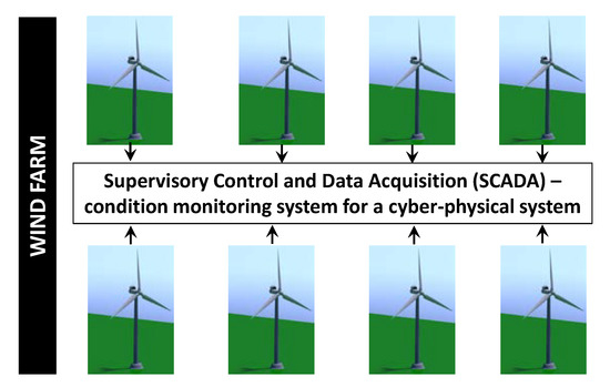
Figure 19.
Condition monitoring for a cyber–physical system (CPS).
Large amounts of data are analyzed in a remote engineering center in order to to monitor the physical behavior and to generate information concerning the condition of all wind turbines of the wind farm and their components such as gear systems, generators, or converters. Hehenberger et al. [58] described a prediction system for this kind of CPS that used SCADA data and applied an adaptive network-based fuzzy inference system (ANFIS). This system can predict a failure of gear systems (Section 3.5). A model for strategic maintenance scheduling of wind farms was proposed by Mazidi et al. [87]; this model allows preventive maintenance scheduling for this kind of CPS. These authors also provided an extensive literature review concerning the design and maintenance of offshore wind turbines.
CPSs are more or less only an intermediate step to cloud-based systems, which add the aspect of global integration and participate in the Internet of Things (IoT) [58]. The interaction of all technical systems with the system that produces them, and with some superordinate monitoring, planning control, and diagnosis system, as well as with co-operating systems and subsystems, plays an important role in the development of a future systems; models of system development need to consider and depict all these interaction processes because, in the future, nearly all physical processes in technical systems will be influenced by these interaction processes. The approaches realized in frameworks for cyber–physical-system development enable horizontal and vertical integration, and can be extended to a global cloud-based scale. Consequently, holistic modelling of abstract physics needs to include these aspects that are crucial for the development of future technical systems.
4.5. Summary
Detailed analysis of four consciously chosen integration approaches leads to the insights that all discussed integration approaches have specific merits, and that holistic integration needs to incorporate aspects and model integration solutions of all integration approaches. It is also obvious that models that are to be integrated are rich enough—they contain all important static and dynamic local and distributed information concerning the abstract and concrete physical behavior—for sensible integration. The integration approaches are compared in Table 2.
Table 2.
Overview of integration approaches.
The central conclusions of this and the previous section are summarized in the next section, and recommendations for further research are given.
5. Conclusions and Recommendations for Further Research
Today, several possibilities to model abstract and concrete physical behavior are available, and several approaches to integrate these models with themselves and other, more abstract or concrete models are proposed. However, no common methodology that describes the holistic modelling of abstract physics is present. Detailed analysis in the two previous sections may explain why this methodology has not yet been developed. This may be because a multitude of perspectives, functions, and dependences need to be present in the models of such a methodology, and model-integration approaches need to be domain- and system-spanning, dynamical, and able to handle multi-perspective models. Both for the models and their integration, numerous promising approaches, models, modelling languages, algorithms, and integration schemes are available. Scientific challenges in the next years are the combination, adaptation, and integration of these elements. The goal is a methodology that allows the interconnected representation of the level of abstract physics that is as complete and conclusive as the representation methodology already present on the concrete level. On this level, a combination of systems and models like computer-aided design (CAD), computer-aided engineering (CAE), product-data management (PDM), product-life-cycle management (PLM) and enterprise-resource planning (ERP) already allows an extremely rich, interconnected, and dynamic representation of technical systems. This paper collected several insights concerning the necessities and possibilities of future models and systems that can represent abstract physics of technical systems. Central insights are:
- The phenomenon-oriented perspective was proposed by design science and has its unique merits but is usually weakly represented in integrated modelling approaches. Initial approaches for the digital modelling of this perspective were proposed in the last few years; however, it remains a promising field for further research.
- For the behavior perspective, a multitude of modelling possibilities are available, but only some are integrated in existing engineering frameworks. Additionally, abstract representations of the behavior perspective are sparse and rarely employed; in this area, further scientific activities are desirable.
- Research concerning the interface-oriented perspective is relatively new; the connection with other modelling attempts and the integration in engineering frameworks is a field for future scientific activities.
- The logic-oriented perspective is relatively well-researched and frequently applied in engineering practice for reliability and safety analyses; links to other system-modelling possibilities are usually still rather weak.
- Numerous modelling possibilities concerning the control-oriented perspective were developed and successfully applied in the last few decades; similar to the logic-oriented perspective, links to other system-modelling possibilities are usually still rather weak.
- Strong links to the requirements concerning a technical system to the functional domain and structural domain are highly desirable in order to avoid repetitive work, inconsistencies, and fault possibilities.
- Engineering frameworks that connect several views in the functional domain may allow an expansion towards a more concrete modelling of abstract physics; further research in this area is desirable.
- In research activities in the area of computational design synthesis, several perspectives concerning the physical behavior of future technical systems are already incorporated.
- Engineering frameworks based on graph-based design languages may allow an expansion towards the more concrete modelling of abstract physics; further scientific activities concerning this expansion have large potential.
- Ontologies and metamodels play a central role in all modelling endeavors; frequently, their investigation is not explicitly addressed, but it is mandatory for the development of future holistic and integrated modelling possibilities in the field of abstract physics.
- As most future complex technical systems are cyber–physical or even cloud-based, the vertical and horizontal integration of information, models, and processes in this field is inevitable; future research has to address this need.
The modelling perspectives of abstract physics and the integration approaches were explained on the basis of wind turbines. Wind turbines, and especially wind-turbine farms, are complex, distributed technical systems that include aspects of mechanics, hydraulics, electrical engineering, electronics, and software. Requirements concerning reliability and safety are enormous, and the number of operation hours is extremely large. Consequently, it is admissible to assume that the presented analysis and conclusions are valuable for other technical systems as well as other energy-generation and -transformation systems (solar systems, power plants, etc.), but also transportation systems (cars, trucks, trains, ships, aircrafts, etc.) and production systems.
Obviously, this paper does not give a conclusive answer on how the abstract physical behavior of technical systems should be modelled in order to enable efficient and effective system-development processes, and the efficient, effective, safe, and reliable production and operation of these technical systems. All languages, modelling approaches, and frameworks have their specific merits, but also their undeniable limitations. This paper gave an overview of existing perspectives and important aspects and explained integration necessities and approaches. It presented structure and promising areas for future research. The creation of holistic and integrated modelling approaches might be the outcome of these research activities. These approaches may lead to more robust and efficient development processes for technical systems and subsystems for energy generation and transformation, and other systems.
Funding
This research was partly funded in the scope of the Digital Product Life. Cycle (ZaFH) project (information under: https://dip.reutlingen-university.de/), which is supported by a grant from the European Regional Development Fund and the Ministry of Science, Research, and the Arts of Baden-Württemberg, Germany (information under: https://efre-bw.de/).
Conflicts of Interest
The author declares no conflict of interest.
References
- Chamas, M.; Paetzold, K. Modeling of Requirement-Based Effect Chains of Mechatronic Systems in Conceptual Stage. Int. J. Electr. Electron. Eng. Telecommun. 2018, 7, 127–134. [Google Scholar] [CrossRef]
- Hruschka, P. Business Analysis und Requirements Engineering: Produkte und Prozesse Nachhaltig Verbessern; Hanser: Munich, Germany, 2019. [Google Scholar] [CrossRef]
- Bernard, R.; Irlinger, R. About watches and cars: Winning R&D strategies in two branches. In Proceedings of the Presentation at the International Symposium “Engineering Design—The Art of Building Networks”, Garching, Germany, 4 April 2016. [Google Scholar]
- Lang, H. Die Methodische Integration Empirischer Analysen in die Frühen Phasen Eines Entwicklungsprozesses. Ph.D. Thesis, Technischen Universität Graz, Graz, Austria, 2016. [Google Scholar]
- Zhang, Z.; Li, X.; Liz, Z. A Closed-loop Based Framework for Design Requirement Management. In Moving Integrated Product Development to Service Clouds in the Global Economy; IOS Press: Amsterdam, The Netherlands, 2014. [Google Scholar]
- Holder, K.; Zech, A.; Ramsaier, M.; Stetter, R.; Niedermeier, H.-P.; Rudolph, S.; Till, M. Model-Based Requirements Management in Gear Systems Design based on Graph-Based Design Languages. Appl. Sci. 2017, 7, 1112. [Google Scholar] [CrossRef]
- Eisenbart, B.; Gericke, K.; Blessing, L.; McAloone, T. A DSM-based Framework for Integrated Function Modeling: Concept, Application and Evaluation. Res. Eng. Des. 2016, 28, 25–51. [Google Scholar] [CrossRef]
- Elwert, M.; Ramsaier, M.; Eisenbart, B.; Stetter, R. Holistic Digital Function Modelling with Graph-Based Design Languages. In Proceedings of the Design Society: International Conference on Engineering Design, Delft, The Netherlands, 5–8 August 2019; Cambridge University Press: Cambridge, UK, 2019; Volume 1, pp. 1523–1532. [Google Scholar] [CrossRef]
- Atkin, R.H. Abstract Physics. In Il Nuovo Cimento; Springer: Berlin, Germany, 1965; Volume XXXVIII, pp. 496–517. [Google Scholar] [CrossRef]
- Gero, J.; Kannengiesser, U. The Function-Behaviour-Structure Ontology of Design. In An Anthology of Theories and Models of Design; Chakrabarti, A., Blessing, L.T.M., Eds.; Springer: Berlin, Germany, 2014. [Google Scholar] [CrossRef]
- Ehrlenspiel, K.; Meerkamm, H. Integrierte Produktentwicklung. Denkabläufe, Methodeneinsatz, Zusammenarbeit; Carl Hanser: Munich, Germany, 2013. [Google Scholar] [CrossRef]
- Lindemann, U. Methodische Entwicklung Technischer Produkte; Methoden flexibel und situationsgerecht anwenden; Springer: Berlin, Germany, 2009. [Google Scholar] [CrossRef]
- Pahl, G.; Beitz, W.; Feldhusen, J.; Grote, K.H. Engineering Design: A Systematic Approach; Springer: Berlin, Germany, 2007. [Google Scholar] [CrossRef]
- Ponn, J.; Lindemann, U. Konzeptentwicklung und Gestaltung Technischer Produkte: Systematisch von Anforderungen zu Konzepten und Gestaltlösungen; Springer: Berlin, Germany, 2011. [Google Scholar] [CrossRef]
- Stetter, R.; Niedermeier, M. Approaches towards Lean Products. In DS 42: Proceedings of ICED 2007, the 16th International Conference on Engineering Design, Paris, France, 28–31 July 2007; Bocquet, J.-C., Ed.; Design Society: Paris, France, 2007. [Google Scholar]
- Wulf, J. Elementarmethoden zur Lösungssuche. Ph.D. Thesis, Technischen Universität München, Munich, Germany, 2001. [Google Scholar]
- Schmitz, J.; Diepeveen, N.F.B.; Vatheuer, N.; Murrenhoff, H. Dynamic transmission response of a hydrostatic transmission measured on a test bench. In Proceedings of the European Wind Energy Conference and Exhibition (EWEA 2012), Copenhagen, Denmark, 16–19 April 2012. [Google Scholar]
- Liu, Z.; Tao, Y.; Wei, L.; Zhan, P.; Yue, D. Analysis of Dynamic Characteristics of a 600 kW Storage Type Wind Turbine with Hybrid Hydraulic Transmission. Processes 2019, 7, 397. [Google Scholar] [CrossRef]
- Mathias, J.; Eifler, T.; Engelhardt, R.; Kloberdanz, H.; Birkhofer, H.; Bohn, A. Selection of Physical Effects Based on Disturbances and Robustness Ratios in the Early Phases of Robust Design. In DS 68-1: Proceedings of the 18th International Conference on Engineering Design (ICED 11), Impacting Society through Engineering Design, Vol. 1: Design Processes, Lyngby/Copenhagen, Denmark, 15–19 August 2011; Culley, S.J., Hicks, B.J., McAloone, T.C., Howard, T.J., Clarkson, J., Eds.; Design Society: Glasgow, UK, 2011. [Google Scholar]
- Helms, B. Object-Oriented Graph Grammars for Computational Design Synthesis. Ph.D. Thesis, Technischen Universität München, Munich, Germany, 2013. [Google Scholar]
- Wagner, C. Funktionsintegration im Rahmen Einer Fertigungsgetriebenen Produktentwicklung. Ph.D. Thesis, Technische Universität, Darmstadt, Germany, 2018. [Google Scholar]
- Williams, J.H. Fundamentals of Applied Dynamics; John Wiley and Sons: Hoboken, NJ, USA, 2004. [Google Scholar] [CrossRef]
- Jafri, S.M.; Eltaher, A.; Paul, J. Dynamics of Offshore Wind Turbines. In Proceedings of the Twenty-first International Offshore and Polar Engineering Conference, Maui, HI, USA, 19–24 June 2011; International Society of Offshore and Polar Engineers (ISOPE): Mountain View, CA, USA, 2011. [Google Scholar]
- Jiang, Z.; Yang, L.; Gao, Z.; Moan, T. Numerical Simulation of a Wind Turbine with a Hydraulic Transmission System. Energy Procedia 2014, 53, 44–55. [Google Scholar] [CrossRef]
- Ramakrishnan, V. Analysis of Wind Turbine Blade Vibration and Drivetrain Loads. Ph.D. Thesis, Michigan State University, East Lansing, MI, USA, 2017. [Google Scholar]
- Ansoategui, I.; Zulueta, E.; Fernandez-Gamiz, U.; Lopez-Guede, J.M. Mechatronic Modeling and Frequency Analysis of the Drive Train of a Horizontal Wind Turbine. Energies 2019, 12, 613. [Google Scholar] [CrossRef]
- Ismaiel, A.; Yoshida, S. Aeroelastic Analysis of a Coplanar Twin-Rotor Wind Turbine. Energies 2019, 12, 1881. [Google Scholar] [CrossRef]
- Chu, J.; Yuan, L.; Hu, Y.; Pan, C.; Pan, L. Comparative Analysis of Identification Methods for Mechanical Dynamics of Large-Scale Wind Turbine. Energies 2019, 12, 3429. [Google Scholar] [CrossRef]
- Li, Q.; Wang, J.; Zhang, Y.; Fan, Y.; Bao, G.; Wang, X. Multi-Period Generation Expansion Planning for Sustainable Power Systems to Maximize the Utilization of Renewable Energy Sources. Sustainability 2020, 12, 1083. [Google Scholar] [CrossRef]
- Ramsaier, M.; Stetter, R.; Till, M.; Rudolph, S.; Schumacher, A. Automatic Definition of Density-driven Topology Optimization with Graph-based Design Languages. In Advances in Structural and Multidisciplinary Optimization; Proceedings of the 12th World Congress of Structural and Multidisciplinary Optimization (WCSMO12), Braunschweig, Germany, 5–9 June 2017; Schumacher, A., Vietor, T., Fiebig, S., Bletzinger, K.U., Maute, K., Eds.; Springer: Cham, Switzerland, 2017. [Google Scholar] [CrossRef]
- Fritzson, P. Principles of Object-Oriented Modeling and Simulation with Modelica 3.3: A Cyber-Physical Approach; John Wiley & Sons: Hoboken, NJ, USA, 2014. [Google Scholar] [CrossRef]
- Vogel, S. An application-independent continuum mechanics interface for virtual engineering. Eng. Comput. 2019, 35, 551–565. [Google Scholar] [CrossRef]
- Münzer, C.; Shea, K. A Simulation-Based CDS Approach: Automated Generation of Simulation Models Based from Generated Concept Model Graphs. In Proceedings of the ASME 2015 International Design Engineering Technical Conference & Computers and Information in Engineering Conference, Boston, MA, USA, 2–5 August 2015; American Society of Mechanical Engineers: New York, NY, USA, 2015. [Google Scholar] [CrossRef]
- Albers, A.; Wintergerst, E. The Contact and Channel Approach (C&C2-A): Relating a system’s physical structure to its functionality, In An Anthology of Theories and Models of Design; Chakrabarti, A., Blessing, L.T.M., Eds.; Springer: London, UK, 2014; pp. 151–171. [Google Scholar] [CrossRef]
- Gladysz, B.; Spandl, L.; Albers, A. A Function- and Embodiment-Based Failure Analysis Method for an In-Depth Understanding of Failure Mechanisms. In Proceedings of the 21st International Conference on Engineering Design ICED17, Vancouver, BC, Canada, 21–25 August 2017; Maier, A., Skec, S., Kim, H., Kokkolaras, M., Oehmen, J., Fadel, G., Salustri, F., Van der Loos, M., Eds.; The Design Society: Glasgow, UK, 2017. [Google Scholar]
- Li, J.; Wang, Z.; Ren, Y.; Yang, D.; Lv, X. A Novel Reliability Estimation Method of Multi-State System Based on Structure Learning Algorithm. Eksploatacja i Niezawodnosc - Maintenance and Reliability 2020, 22, 170–178. [Google Scholar] [CrossRef]
- Gausemeier, J.; Pöschl, M.; Deyter, S.; Kaiser, L. Modeling and Analyzing Fault-tolerant Mechatronic Systems. In DS 58-1: Proceedings of ICED 09, the 17th International Conference on Engineering Design, Vol. 1, Design Processes, Palo Alto, CA, USA, 24–27 August 2009; Norell Bergendahl, M., Grimheden, M., Leifer, L., Skogstad, P., Lindemann, U., Eds.; The Design Society: Glasgow, UK, 2009. [Google Scholar]
- Dorociak, R.; Gausemeier, J. Modeling of the Failure Propagation of an Advanced Mechatronic System within the Specification of its Principle Solution. In Proceedings of the international design conference DESIGN 2012, Dubrovnik, Croatia, 21–24 May 2012; Marjanovic, D., Storga, M., Pavkovic, P., Bojcetic, N., Eds.; The Design Society: Glasgow, UK, 2012. [Google Scholar]
- Mhenni, F.; Choley, J.Y.; Rivière, A.; Nguyen, N.; Kadima, H. SysML and Safety Analysis for Mechatronic Systems. In Proceedings of the 2012 9th France-Japan & 7th Europe-Asia Congress on Mechatronics (MECATRONICS)/13th International Workshop on Research and Education in Mechatronics (REM), Paris, France, 21–23 November 2012. [Google Scholar]
- Mhenni, F. Safety Analysis Integration in a Systems Engineering Approach for Mechatronic Systems Design. Ph.D. Thesis, Ecole Centrale Paris, Châtenay-Malabry, France, 2014. [Google Scholar]
- Stetter, R. Fault-Tolerant Design and Control of Automated Vehicles and Processes; Insights for the Synthesis of Intelligent Systems; Springer: Berlin, Germany, 2020. [Google Scholar] [CrossRef]
- Kececioglu, D. Reliability Engineering Handbook; John Wiley & Sons: Hoboken, NJ, USA, 2002; Volume 2. [Google Scholar]
- Vedachalam, N.; Umapathy, A.; Ramadass, G.A. Fault-Tolerant Design Approach for Reliable Offshore Multi-Megawatt Variable Frequency Converters. J. Ocean Eng. Sci. 2016, 1, 226–237. [Google Scholar] [CrossRef]
- Dubrova, E. Fault-Tolerant Design; Springer: Berlin, Germany, 2013. [Google Scholar] [CrossRef]
- Song, X.; Zhai, Z.; Liu, Y.; Han, J. A Stochastic Approach for the Reliability Evaluation of Multi-State Systems with Dependent Components. Reliab. Eng. Syst. Saf. 2018, 170, 257–266. [Google Scholar] [CrossRef]
- Bruch, C. Handling Undesired Functions during Conceptual Design—A State and State Transition-based Approach. In DS 32: Proceedings of DESIGN 2004, the 8th International Design Conference, Dubrovnik, Croatia, 18–21 May 2004; Marjanovic, D., Ed.; The Design Society: Glasgow, UK, 2004. [Google Scholar]
- Peng, R. Reliability of Interdependent Networks with Cascading Failures. Eksploatacja i Niezawodnosc 2018, 20, 273–277. [Google Scholar] [CrossRef]
- Zhang, C.; Zhang, Y. Common Cause and Load-Sharing Failures-Based Reliability Analysis for Parallel Systems. Eksploatacja i Niezawodnosc 2020, 22, 26–34. [Google Scholar] [CrossRef]
- Njindam, T.S.; Paetzold, K. Design for Reliability: An Event- and Function-Based Framework for Failure Behavior Analysis in the Conceptual Design of Cognitive Products. In DS 68-1: Proceedings of the 18th International Conference on Engineering Design (ICED 11), Impacting Society through Engineering Design, Vol. 1: Design Processes, Lyngby/Copenhagen, Denmark, 15–19 August 2011; Culley, S.J., Hicks, B.J., McAloone, T.C., Howard, T.J., Clarkson, J., Eds.; The Design Society: Glasgow, UK, 2011. [Google Scholar]
- Witczak, M. Fault Diagnosis and Fault-Tolerant Control Strategies for Non-Linear Systems; Analytical and Soft Computing Approaches; Springer: Berlin, Germany, 2014. [Google Scholar]
- Hackl, C.; Jané-Soneira, P.; Pfeifer, M.; Schechner, K.; Hohmann, S. Full- and Reduced-Order State-Space Modeling of Wind Turbine Systems with Permanent Magnet Synchronous Generator. Energies 2018, 11, 1809. [Google Scholar] [CrossRef]
- Adams, D. Health Monitoring of Structural Materials and Components: Methods with Applications; John Wiley & Sons: Hoboken, NJ, USA, 2007. [Google Scholar]
- Farrar, C.R.; Worden, K. An Introduction to Structural Health Monitoring. Philos. Trans. R. Soc. A Math. Phys. Eng. Sci. 2007, 365, 303–315. [Google Scholar] [CrossRef]
- Isermann, R. Fault Diagnosis Systems. An Introduction from Fault Detection to Fault Tolerance; Springer: New York, NY, USA, 2006. [Google Scholar] [CrossRef]
- Ramsaier, M.; Holder, K.; Zech, A.; Stetter, R.; Rudolph, S.; Till, M. Digital representation of product functions in multicopter design. In Proceedings of the 21st International Conference on Engineering Design (ICED 17) Vol 1: Resource Sensitive Design, Design Research Applications and Case Studies, Vancouver, BC, Canada, 21–25 August 2017; Maier, A., Škec, S., Kim, H., Kokkolaras, M., Oehmen, J., Fadel, G., Salustri, F., Van der Loos, M., Eds.; The Design Society: Glasgow, UK, 2017. [Google Scholar]
- Wu, Y.; Peng, G.; Wang, H.; Zhang, H. Two-Stage Fault Tolerance Method for Large-Scale Manufacturing Network. IEEE Access 2019, 7, 81574–81592. [Google Scholar] [CrossRef]
- Habibi, H.; Nohooji, H.R.; Howard, I.; Simani, S. Fault-Tolerant Neuro Adaptive Constrained Control of Wind Turbines for Power Regulation with Uncertain Wind Speed Variation. Energies 2019, 12, 4712. [Google Scholar] [CrossRef]
- Hehenberger, P.; Vogel-Heuser, B.; Bradley, D.; Eynard, B.; Tomiyama, T.; Achiche, S. Design, Modelling, Simulation and Integration of Cyber Physical Systems: Methods and Applications. Comput. Ind. 2016, 82, 273–289. [Google Scholar] [CrossRef]
- Rigger, E.; Münzer, C.; Shea, K. Estimating the Potential of State of the Art Design Automation—Tasks, Methods, and Benefits. In Proceedings of the DESIGN 2016, 14th International Design Conference, Dubrovnik, Croatia, 16–19 May 2016; Marjanovic, D., Storga, M., Neven, G., Bojcetic, N., Stanko, S., Eds.; The Design Society: Glasgow, UK, 2016; Volume 1, pp. 421–432. [Google Scholar]
- Bolognini, F.; Jauregui Becker, J.M.; Schotborch, W.O. An investigation into limited integration of computational design synthesis in common design practice. In DS 70: Proceedings of DESIGN 2012, the 12th International Design Conference, Dubrovnik, Croatia, 21–24 May 2012; Marjanovic, D., Storga, M., Pavkocic, P., Bojcetic, B., Eds.; The Design Society: Glasgow, UK, 2012; pp. 727–736. [Google Scholar]
- Entner, D.; Prante, T.; Vosgien, T.; Zăvoianu, A.; Saminger-Platz, S.; Schwarz, M.; Fink, K. Potential Identification and Industrial Evaluation of an Integrated Design Automation Workflow. J. Eng. Des. Technol. 2019, 17, 1085–1109. [Google Scholar] [CrossRef]
- Antonsson, E.K.; Cagan, J. Formal Engineering Design Synthesis; Cambridge University Press: Cambridge, UK, 2001. [Google Scholar]
- Wölkl, S.; Shea, K. A Computational Product Model for Conceptual Design using SYSML. In Proceedings of the ASME 2009 International Design Engineering Technical Conferences & Computers and Information in Engineering Conference, IDETC/CIE 2009, San Diego, CA, USA, 30 August–2 September 2009. [Google Scholar] [CrossRef]
- Muenzer, C.; Shea, K. Simulation-Based Computational Design Synthesis using Automated Generation of Simulation Models from Concept Model Graphs. J. Mech. Des. 2017, 139, 071101. [Google Scholar] [CrossRef]
- Münzer, C.; Helms, B.; Shea, K. Automatically Transforming Object-Oriented Graph-Based Representations into Boolean Satisfiability Problems for Computational Design Synthesis. J. Mech. Des. 2013, 135. [Google Scholar] [CrossRef]
- Königseder, C.; Stankovic, T.; Shea, K. Improving Design Grammar Development and Application Through Network-Based Analysis of Transition Graphs. Des. Sci. 2016, 2, 1–34. [Google Scholar] [CrossRef][Green Version]
- Rigger, E.; Vosgien, T. Design Automation State of Practice—Potential and Opportunities. In DS 92: Proceedings of the DESIGN 2018 15th International Design Conference, Dubrovnik, Croatia, 21–24 May 2018; Marianovic, D., Štorga, M., Škec, S., Bojčetić, N., Pavković, N., Eds.; The Design Society: Glasgow, UK, 2018. [Google Scholar] [CrossRef]
- Rigger, E.; Lutz, A.; Shea, K.; Stankovic, T. Estimating the Impact of Design Automation: The Influence of Knowledge on Potential Estimation. In DS 94: Proceedings of the Design Society: 22nd International Conference on Engineering Design (ICED19) Responsible Design for Our Future, Delft, The Netherlands, 5–8 August 2019; The Design Society: Glasgow, UK, 2019. [Google Scholar]
- Rudolph, S. Übertragung von Ähnlichkeitsbegriffen. Habilitationsschrift, Fakultät Luft- und Raumfahrttechnik und Geodäsie. Habilitation thesis, Universität Stuttgart, Stuttgart, Germany, 2002. [Google Scholar]
- Alber, R.; Rudolph, S. On a Grammar-Based Design Language That Supports Automated Design Generation and Creativity. In Knowledge Intensive Design Technology; Borg, J.C., Farrugia, P.J., Camilleri, K.P., Eds.; Springer: Boston, MA, USA, 2004; pp. 19–35. [Google Scholar] [CrossRef]
- Groß, J. Aufbau und Einsatz von Entwurfssprachen zur Auslegung von Satelliten. Doctoral dissertation, Institut für Statik und Dynamik der Luft- und Raumfahrtkonstruktionen. Universität Stuttgart, Stuttgart, Germany, 2013. [Google Scholar]
- Wünsch, F.; Ramsaier, M.; Breckle, T.; Stetter, R.; Till, M.; Rudolph, S. Executable Cost-Sensitive Product Development of a Self-Balancing Two-Wheel Scooter with Graph-Based Design Languages. In DS 92: Proceedings of the DESIGN 2018 15th International Design Conference, Dubrovnik, Croatia, 21–24 May 2018; Marjanović, D., Štorga, M., Škec, S., Bojčetić, N., Pavković, N., Eds.; The Design Society: Glasgow, UK, 2018. [Google Scholar] [CrossRef]
- Walter, B.; Kaiser, D.; Rudolph, S. Machine-executable Model-based Systems Engineering with design languages. In Complex Systems Design & Management; Banach, R., Razavi, J., Lesecq, S., Debicki, O., Mareau, N., Foucault, J., Correvon, M., Dudnik, G., Eds.; Springer: Berlin, Germany, 2019. [Google Scholar] [CrossRef]
- Zech, A.; Stetter, R.; Holder, K.; Rudolph, S.; Till, M. Novel approach for a holistic and completely digital represented product development process by using graph-based design languages. Procedia CIRP 2019, 79, 568–573. [Google Scholar] [CrossRef]
- Ramsaier, M.; Spindler, C.; Stetter, R.; Rudolph, S.; Till, M. Digital representation in multicopter design along the product life-cycle. Procedia CIRP 2017, 62, 559–564. [Google Scholar] [CrossRef]
- IILS mbH. Design Compiler 43. Available online: https://www.iils.de (accessed on 18 March 2020).
- Ramsaier, M.; Stetter, R.; Till, M.; Rudolph, S. Abstract Physics Representation of a Balanced Two-Wheel Scooter in Graph-Based Design Languages. In Proceedings of the Accepted for the 16th international design conference DESIGN 2020 and publication in the proceedings published by the Design Society, Cavtat, Croatia, 26–29 October 2020. [Google Scholar]
- Kiefer, J.; Stetter, R.; Rudolph, S.; Till, M. Graphenbasierte Entwurfssprachen für die digitale Konzeptplanung von Montageanlagen. Ingenieurspiegel 2018, 3, 47–49. [Google Scholar]
- Reichwein, A. Application-specific UML Profiles for Multidisciplinary Product Data Integration. Doctoral Dissertation, Universität Stuttgart, Stuttgart, Germany, 2011. [Google Scholar]
- Pietrusewicz, K. Metamodelling for Design of Mechatronic and Cyber-Physical Systems. Appl. Sci. 2019, 9, 376. [Google Scholar] [CrossRef]
- Rajkumar, R. A Cyber-physical Future. Proc. IEEE 2012, 100, 1309–1312. [Google Scholar] [CrossRef]
- Zheng, C.; Hehenberger, P.; Le Duigou, J.; Bricogne, M.; Eynard, B. Multidisciplinary Design Methodology for Mechatronic Systems Based on Interface Model. Res. Eng. Des. 2017, 28, 333–356. [Google Scholar] [CrossRef]
- Barbieri, G.; Fantuzzi, C.; Borsare, R. A Model-Based Design Methodology for The Development of Mechatronic Systems. Mechatronics 2014, 24, 833–843. [Google Scholar] [CrossRef]
- Guerineau, B.; Zheng, C.; Bricogne, M.; Durupt, A.; Rivest, L.; Rowson, H.; Eynard, B. Management of Heterogeneous Information for Integrated Design of Multidisciplinary Systems. Procedia CIRP 2017, 60, 320–325. [Google Scholar] [CrossRef]
- Nazari, S.; Sonntag, C.; Engell, S. A Modelica-Based Modeling and Simulation Framework for Large-Scale Cyber Physical Systems of Systems. IFAC PapersOnLine 2015, 48, 920–921. [Google Scholar] [CrossRef]
- Chen, C.; Cao, H.; Su, S.; Chen, H.; Gong, Y.; Chen, G. A Unified Modelling Method for Cyber-Physical Systems Based on Modelica. Int. J. Wirel. Mob. Comput. 2019, 16, 350–357. [Google Scholar] [CrossRef]
- Mazidi, P.; Tohidi, Y.; Sanz-Bobi, M.A. Strategic Maintenance Scheduling of an Offshore Wind Farm in a Deregulated Power System. Energies 2017, 10, 3. [Google Scholar] [CrossRef]


© 2020 by the author. Licensee MDPI, Basel, Switzerland. This article is an open access article distributed under the terms and conditions of the Creative Commons Attribution (CC BY) license (http://creativecommons.org/licenses/by/4.0/).