Consensus Control for Reactive Power Sharing Using an Adaptive Virtual Impedance Approach


Abstract
1. Introduction
2. Background
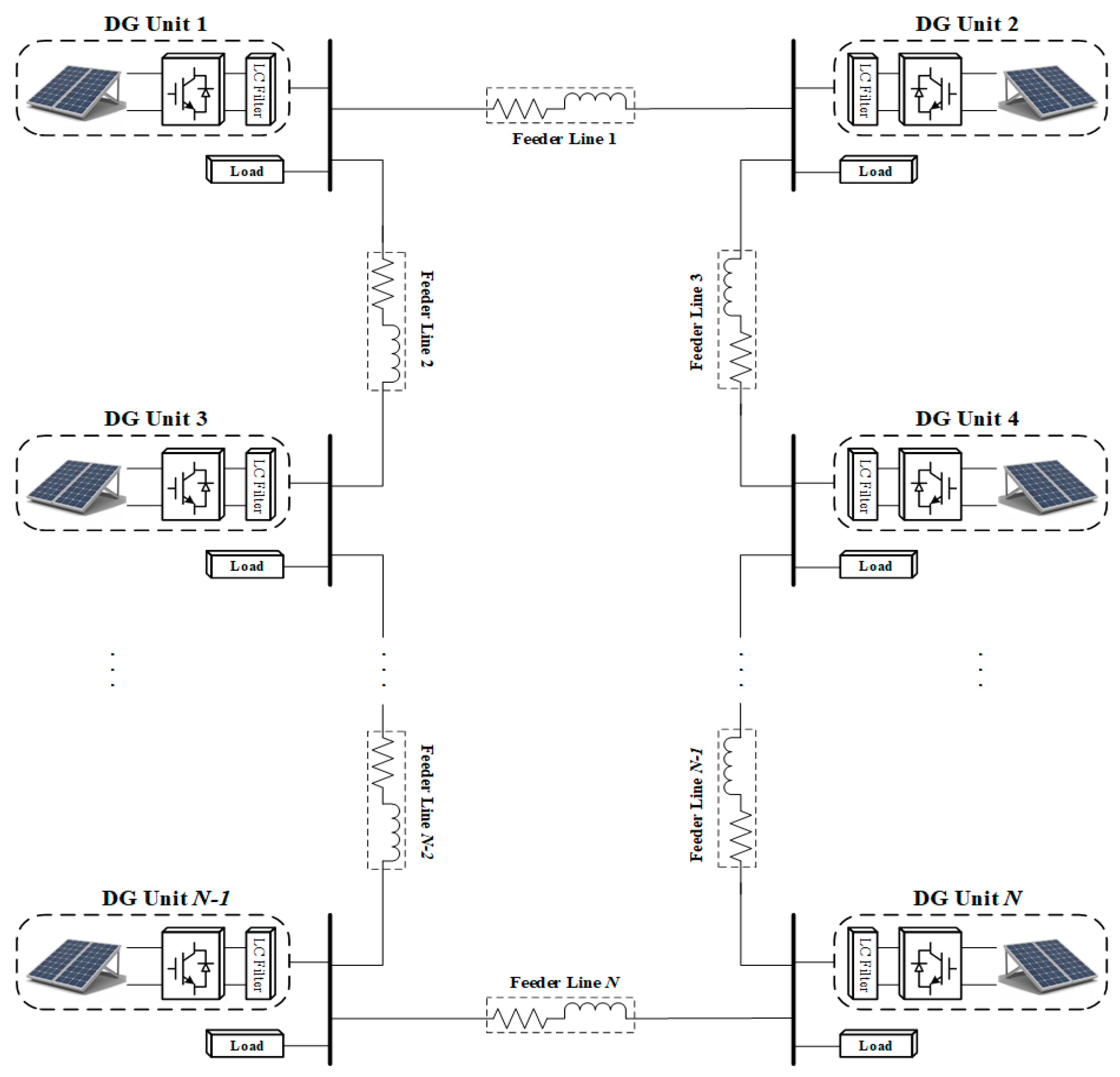
2.1. Modeling of AC Electrical Network of a Microgrid
2.2. Modeling of the Communication Network of the Microgrid
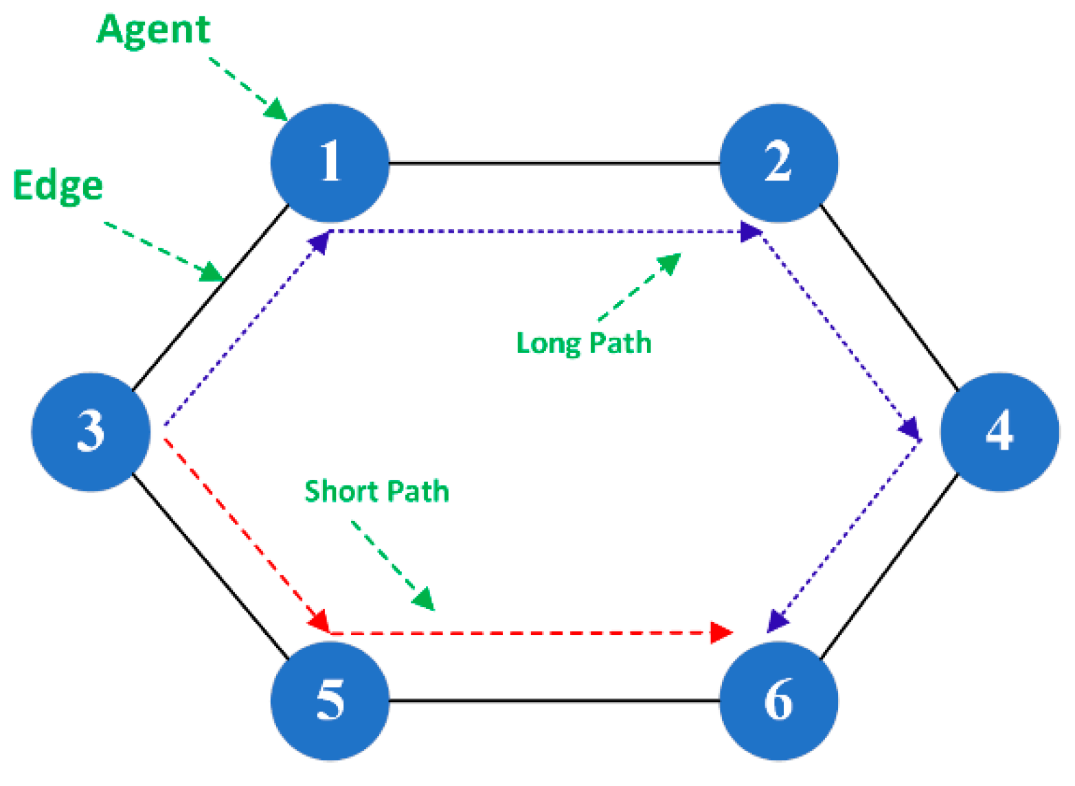
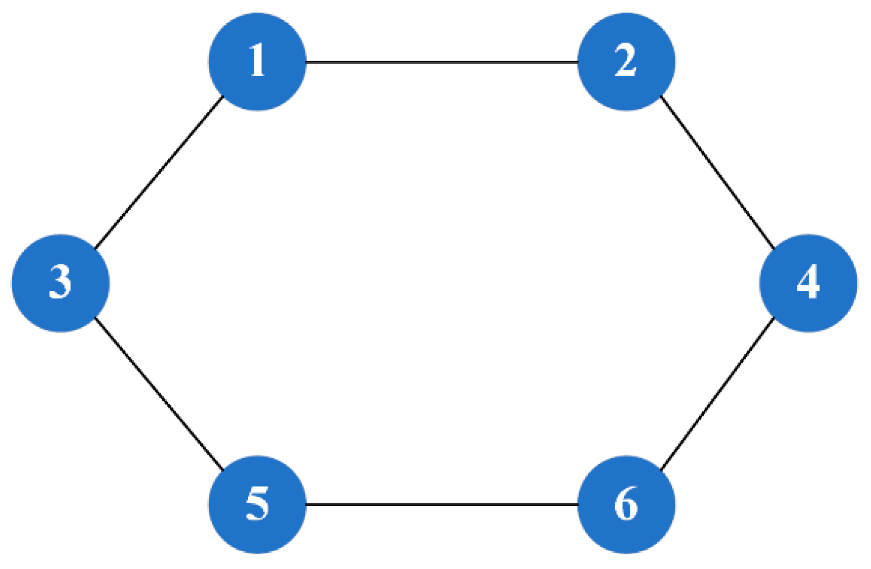
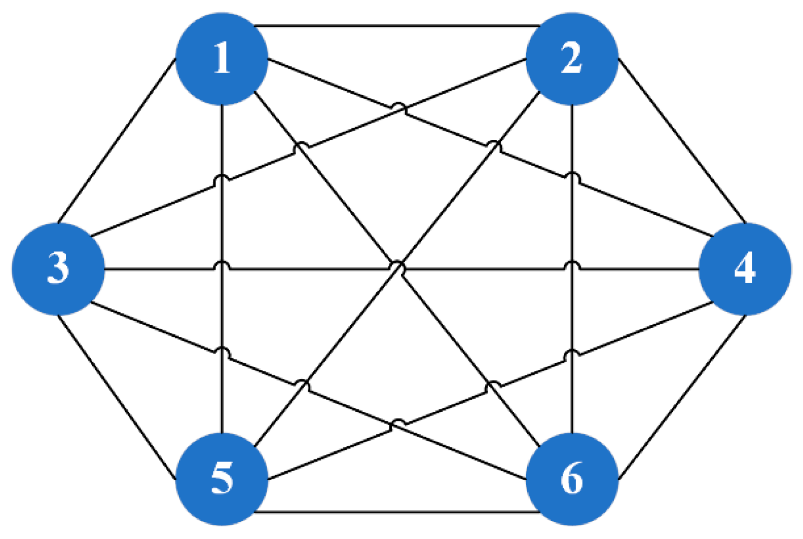
2.2.1. A Graph Theory Approach
2.2.2. Communication Topology
3. Assumptions and Methods
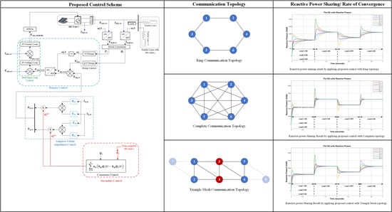
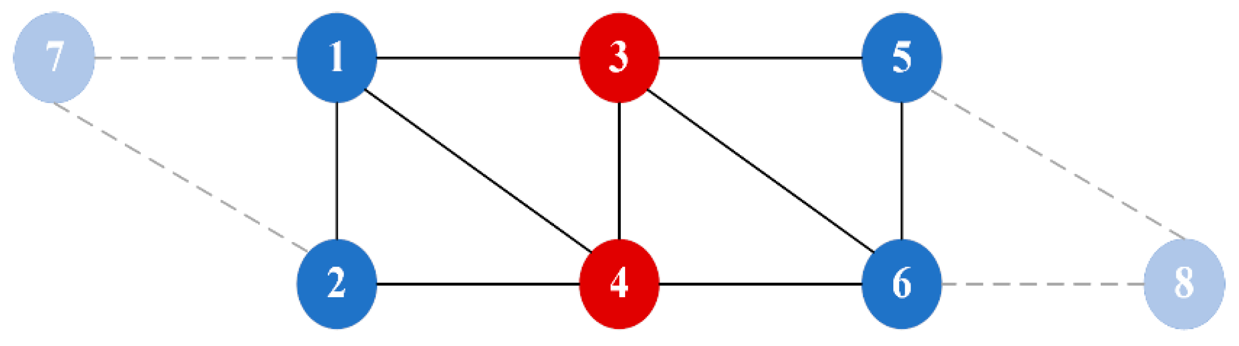
3.1. Proposed Communication Topology
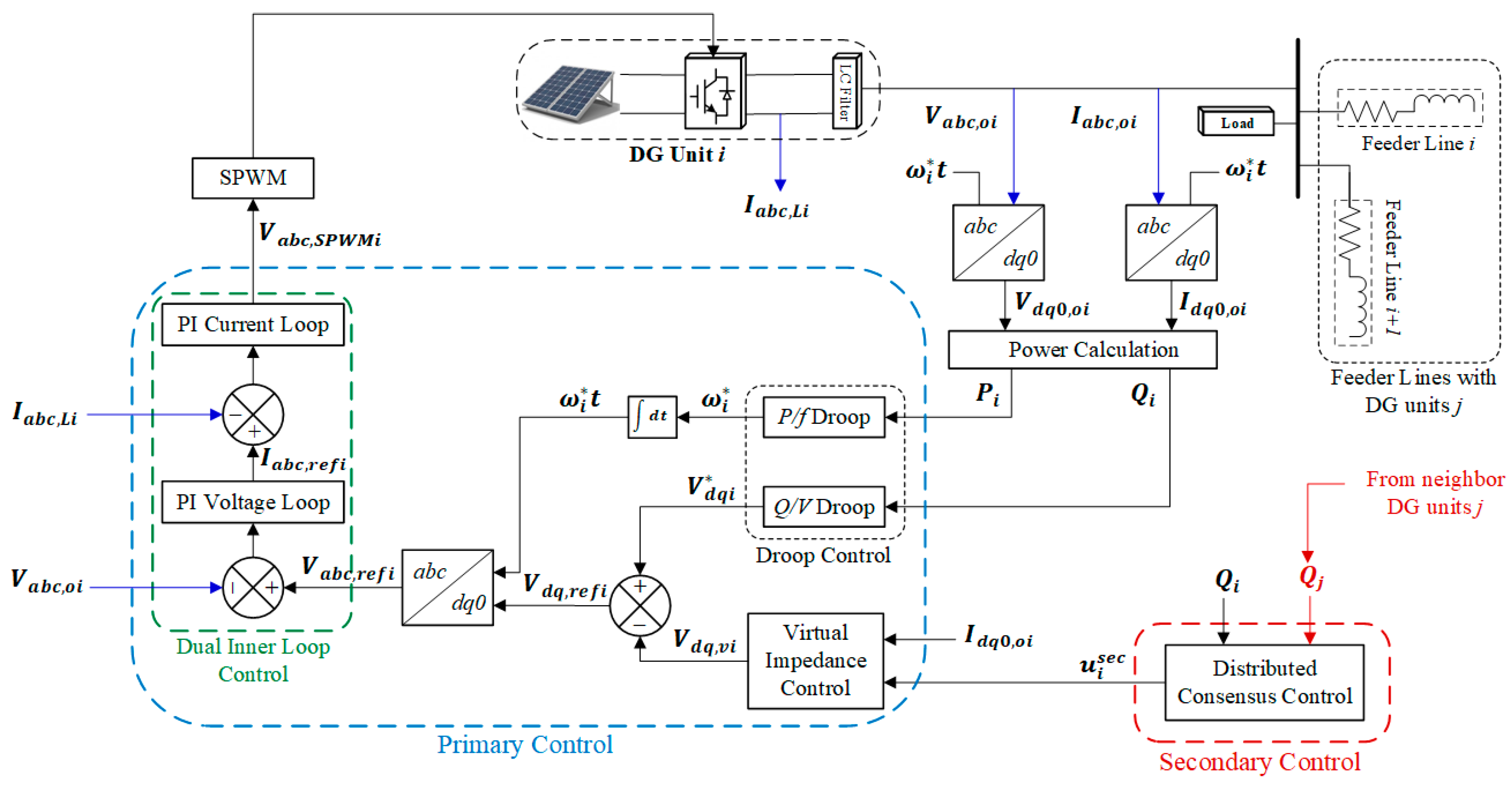
3.2. Mathematical Model of the Proposed Control Method
3.2.1. Primary Control
Droop Control
Virtual Impedance Control
Outer Voltage and Inner Current Dual Loop Control
3.2.2. Secondary Control
Reactive Power Sharing
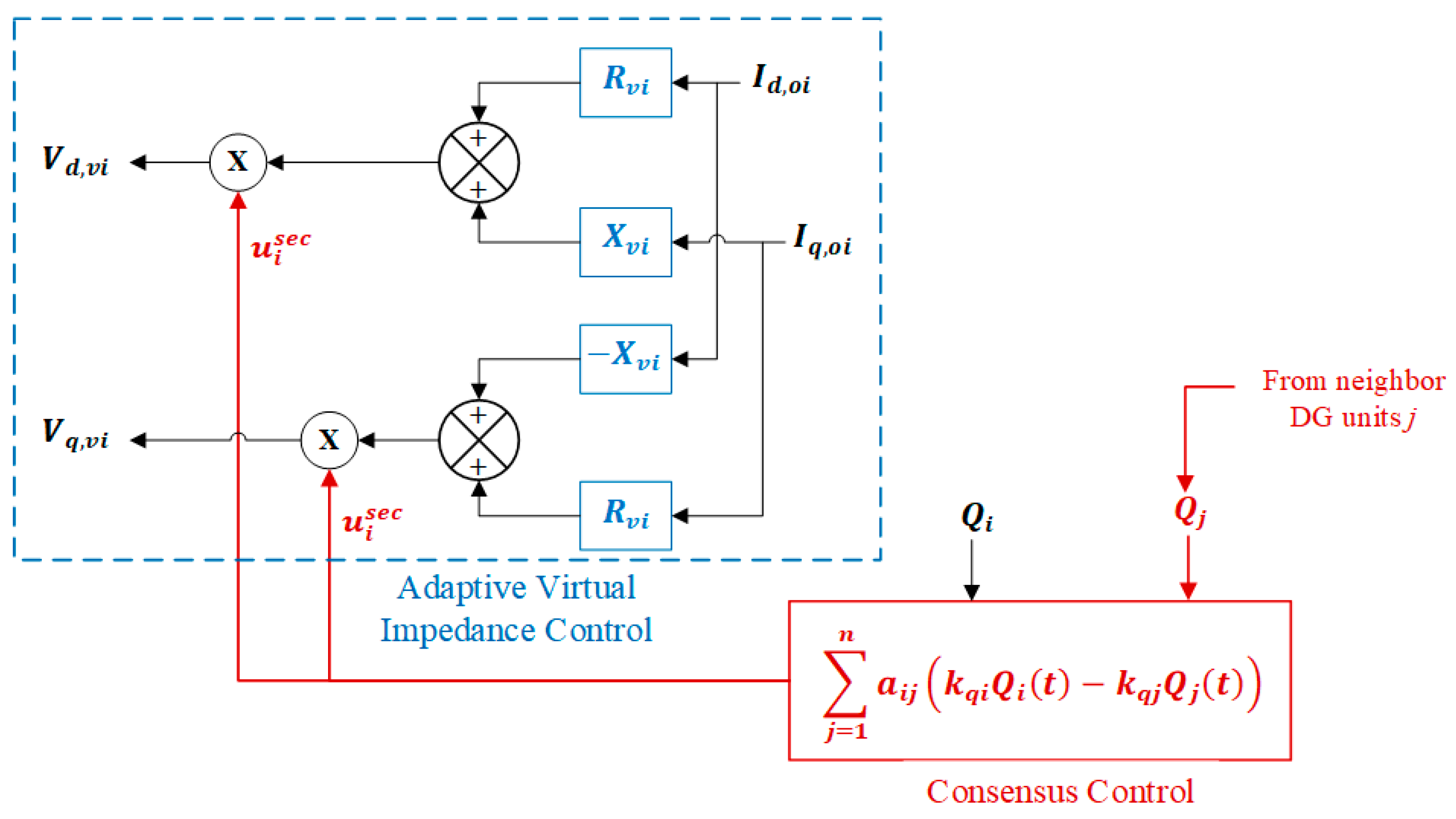
Adaptive Virtual Impedance Control
Consensus Control
Theorems and Lemmas
Reactive Power Sharing Based on Consensus Control
Stability Analysis of Consensus Control
Overall Control
4. Results and Discussion
4.1. Case Study
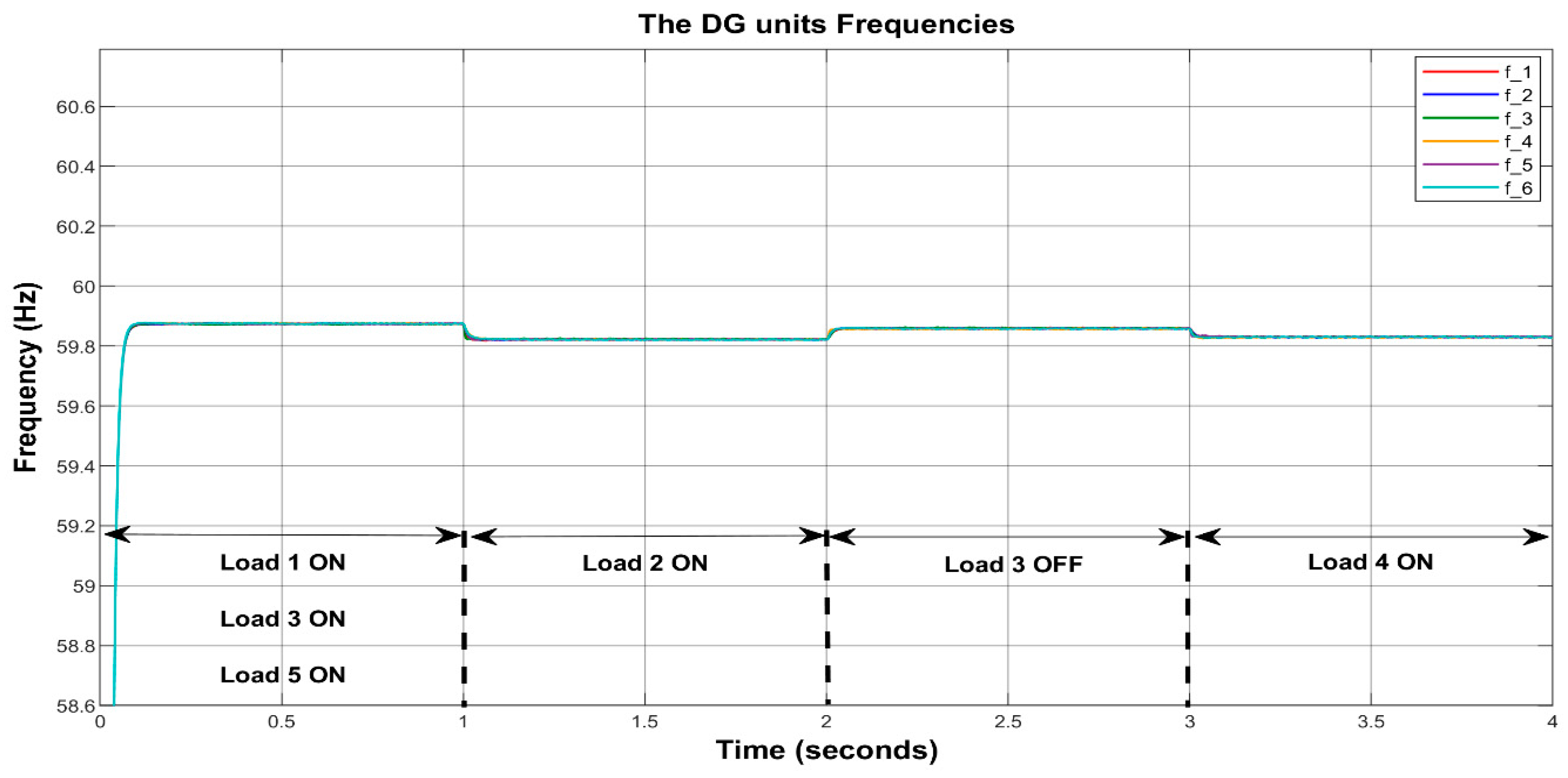
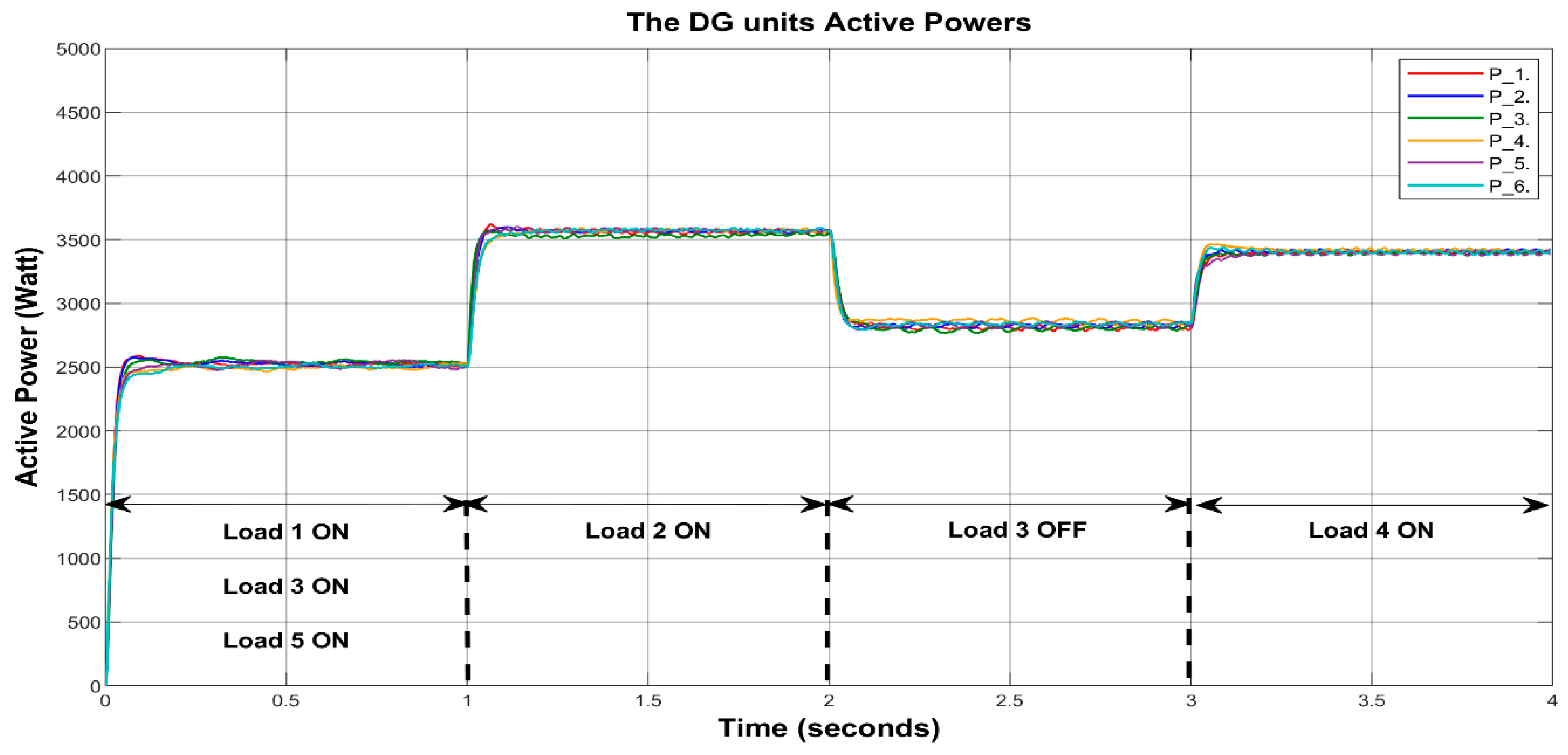
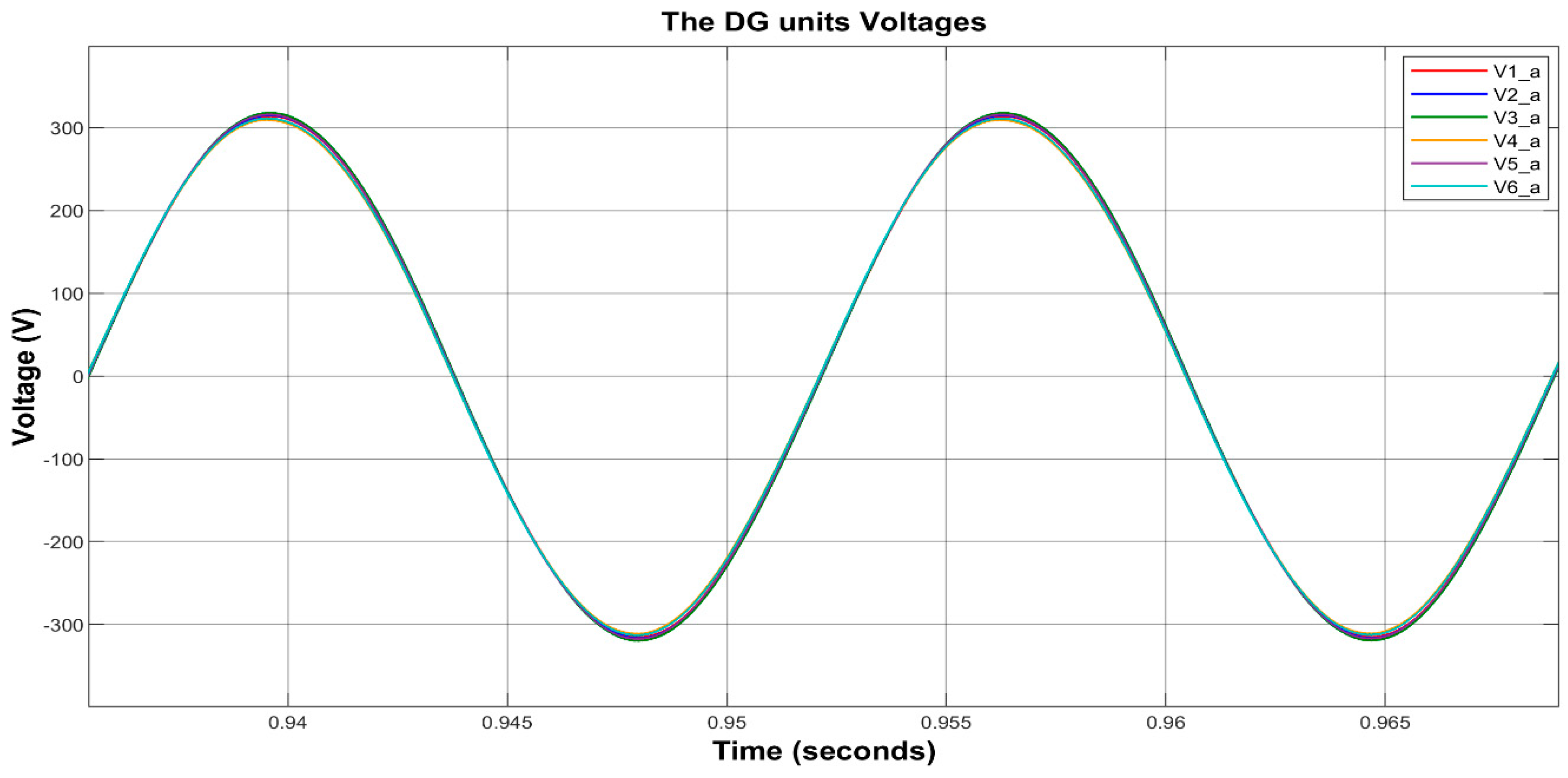
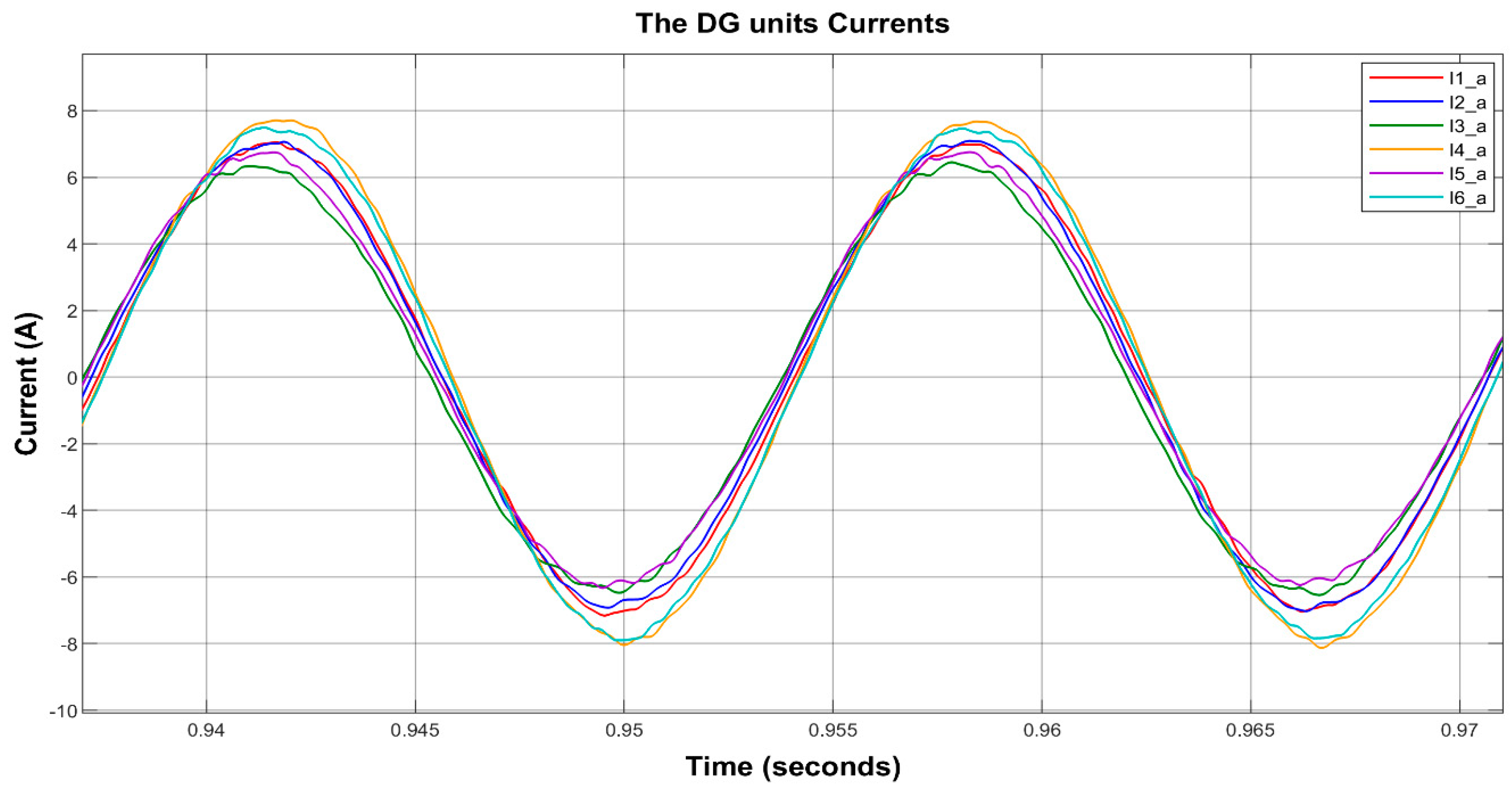
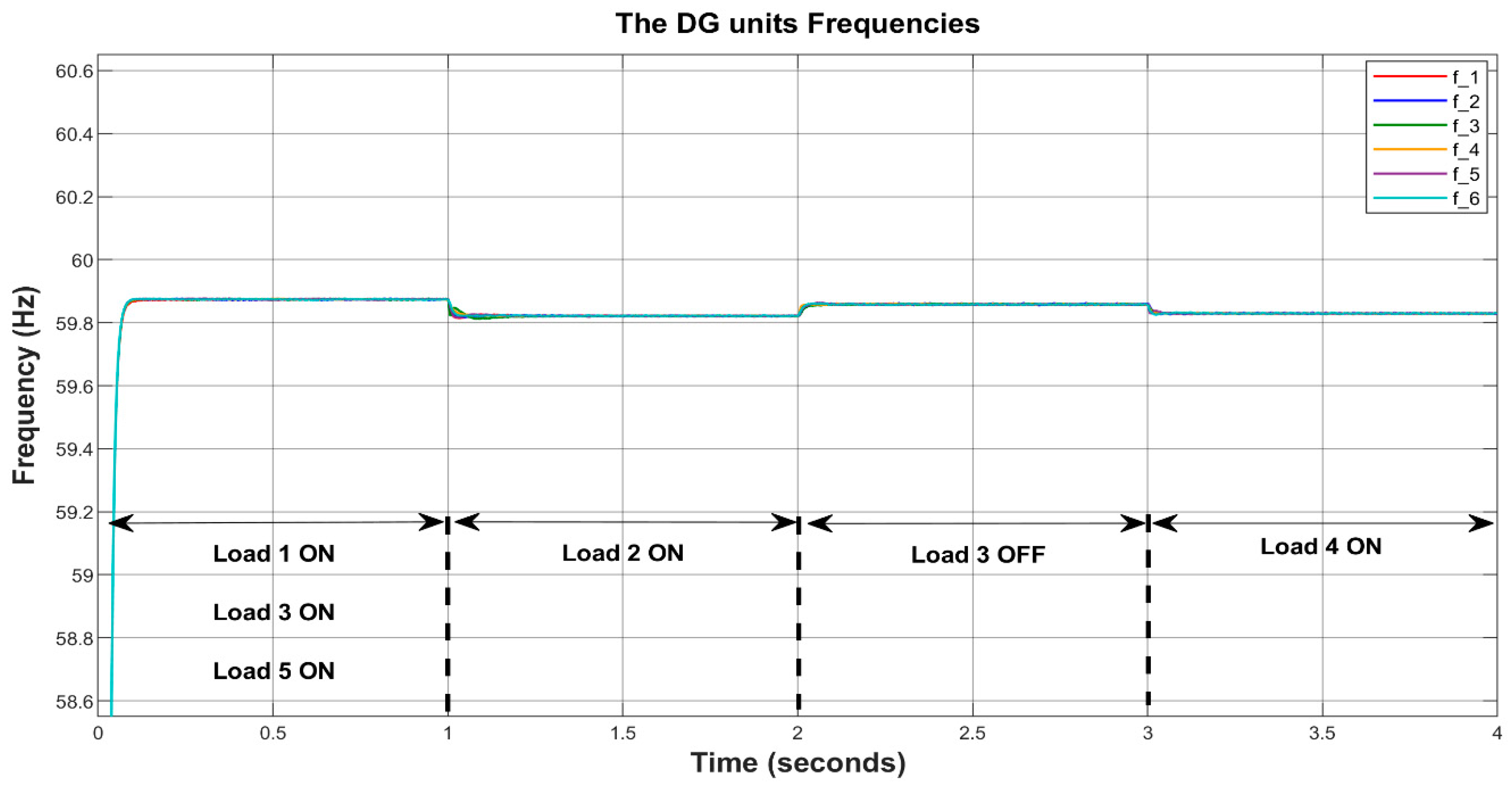
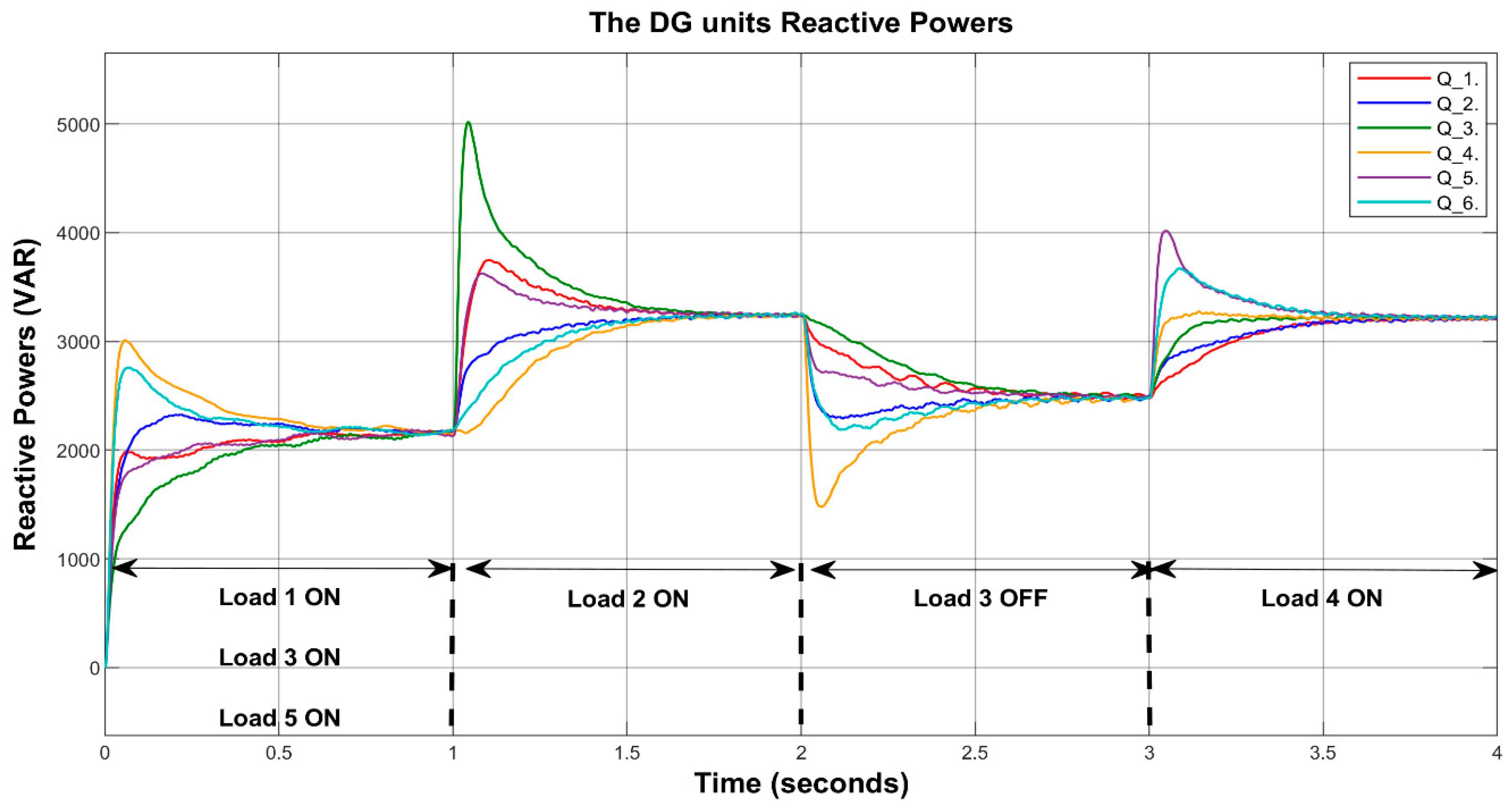
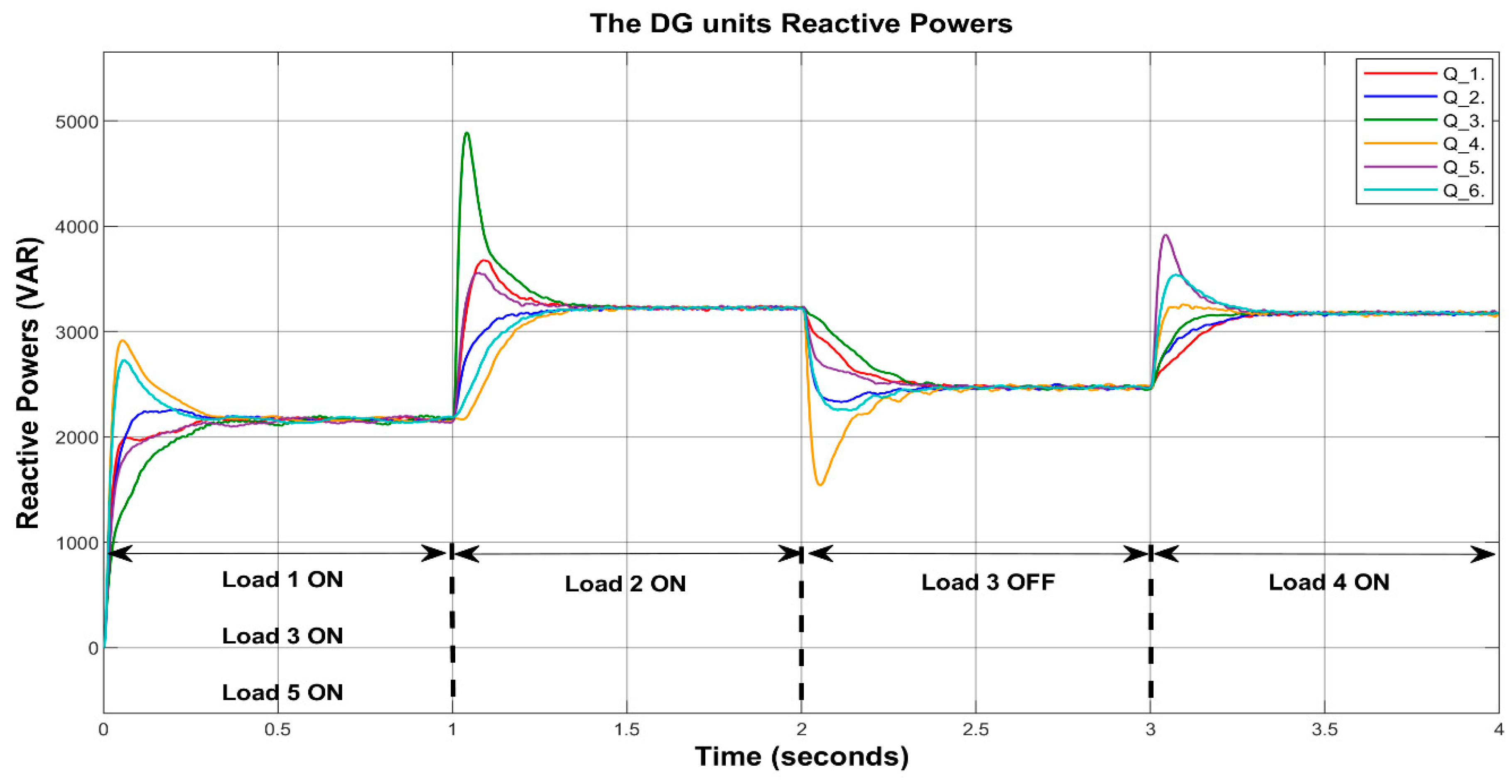
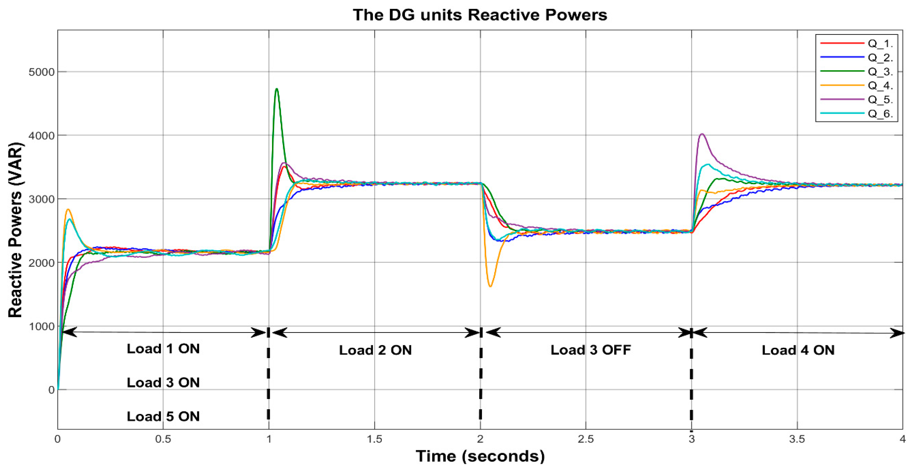
4.1.1. Case 1: Primary Control Alone
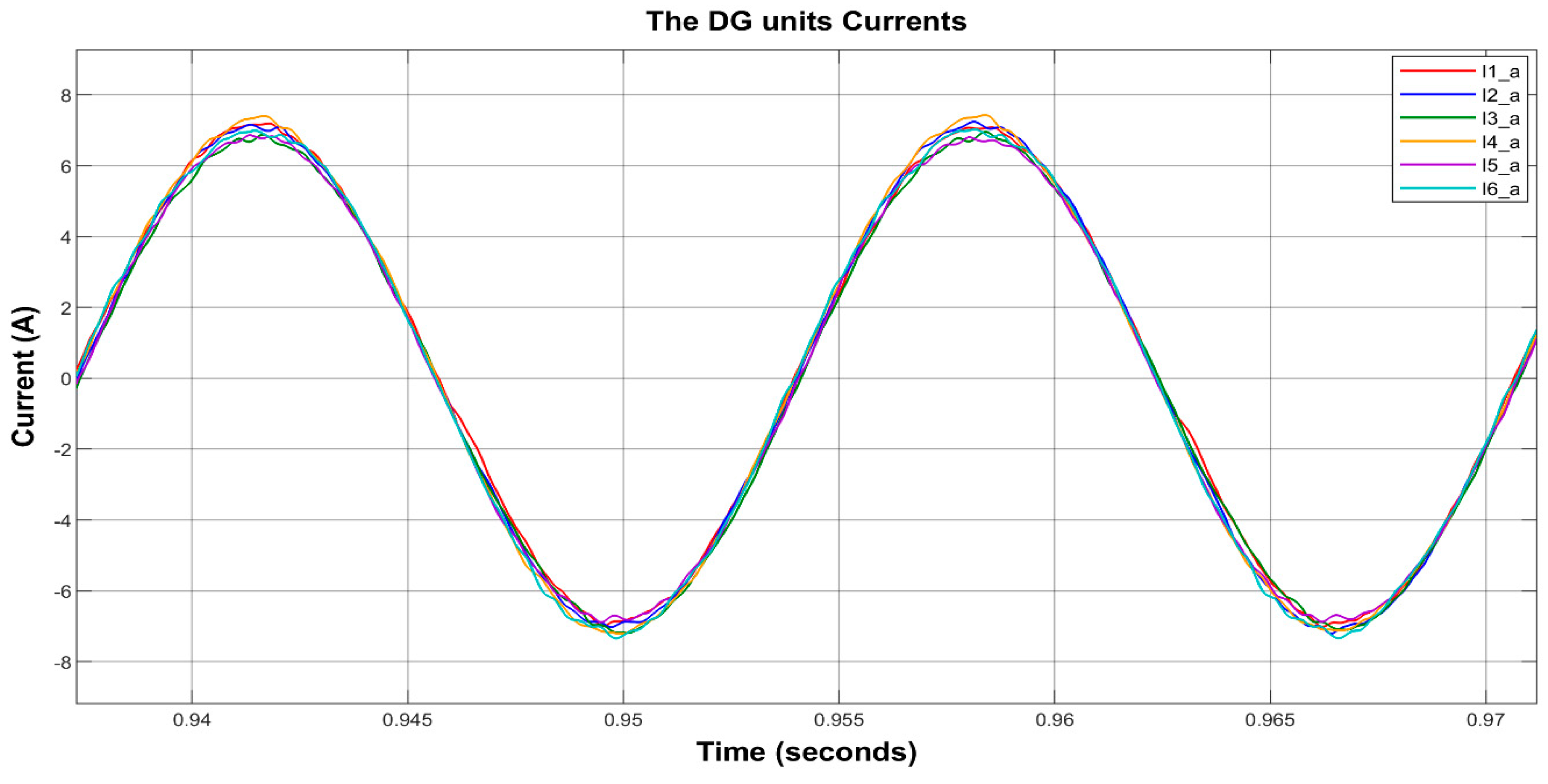
4.1.2. Case 2: Leaderless Consensus Control with Ring Communication Topology
4.1.3. Case 3: Leader-Followers Consensus Control with Ring Communication Topology
4.1.4. Case 4: Leaderless Consensus Control with Complete Communication Topology
4.1.5. Case 5: Leaderless Consensus Control with Triangle Mesh Communication Topology
5. Conclusions
Author Contributions
Funding
Conflicts of Interest
References
- John, B.; Ghosh, A.; Zare, F. Droop control in low voltage islanded microgrids for sharing nonlinear and unbalanced loads. In Proceedings of the 2017 IEEE Region 10 Symposium (TENSYMP), Cochin, India, 14–16 July 2017; pp. 1–5. [Google Scholar] [CrossRef]
- Baojin, L.; Zeng, L.; Jinjun, L.; Teng, W.; Ronghui, A. A novel unbalanced power sharing control method for an islanded microgrid. In Proceedings of the 2017 IEEE 3rd International Future Energy Electronics Conference and ECCE Asia (IFEEC 2017—ECCE Asia), Kaohsiung, Taiwan, 3–7 June 2017; pp. 1617–1622. [Google Scholar] [CrossRef]
- Han, H.; Hou, X.; Yang, J.; Wu, J.; Su, M.; Guerrero, J.M. Review of Power Sharing Control Strategies for Islanding Operation of AC Microgrids. IEEE Trans. Smart Grid 2016, 7, 200–215. [Google Scholar] [CrossRef]
- Han, Y.; Li, H.; Shen, P.; Coelho, E.A.A.; Guerrero, J.M. Review of Active and Reactive Power Sharing Strategies in Hierarchical Controlled Microgrids. IEEE Trans. Power Electron. 2017, 32, 2427–2451. [Google Scholar] [CrossRef]
- Yao, W.; Chen, M.; Matas, J.; Guerrero, J.M.; Qian, Z.-M. Design and Analysis of the Droop Control Method for Parallel Inverters Considering the Impact of the Complex Impedance on the Power Sharing. IEEE Trans. Ind. Electron. 2011, 58, 576–588. [Google Scholar] [CrossRef]
- Guerrero, J.M.; Chandorkar, M.; Lee, T.-L.; Loh, P.C. Advanced Control Architectures for Intelligent Microgrids—Part I: Decentralized and Hierarchical Control. IEEE Trans. Ind. Electron. 2013, 60, 1254–1262. [Google Scholar] [CrossRef]
- De Souza, W.F.; Severo-Mendes, M.A.; Lopes, L.A.C. Power sharing control strategies for a three-phase microgrid in different operating condition with droop control and damping factor investigation. IET Renew. Power Gener. 2015, 9, 831–839. [Google Scholar] [CrossRef]
- Kim, J.; Guerrero, J.M.; Rodriguez, P.; Teodorescu, R.; Nam, K. Mode Adaptive Droop Control With Virtual Output Impedances for an Inverter-Based Flexible AC Microgrid. IEEE Trans. Power Electron. 2011, 26, 689–701. [Google Scholar] [CrossRef]
- Guerrero, J.M.; Berbel, N.; Matas, J.; de Vicuna, L.G.; Miret, J. Decentralized Control for Parallel Operation of Distributed Generation Inverters in Microgrids Using Resistive Output Impedance. In Proceedings of the IECON 2006—32nd Annual Conference on IEEE Industrial Electronics, Paris, France, 6–10 November 2006; pp. 5149–5154. [Google Scholar] [CrossRef]
- Shafiee, Q.; Guerrero, J.M.; Vasquez, J.C. Distributed Secondary Control for Islanded Microgrids—A Novel Approach. IEEE Trans. Power Electron. 2014, 29, 1018–1031. [Google Scholar] [CrossRef]
- Shafiee, Q.; Stefanović, Č.; Dragičević, T.; Popovski, P.; Vasquez, J.C.; Guerrero, J.M. Robust Networked Control Scheme for Distributed Secondary Control of Islanded Microgrids. IEEE Trans. Ind. Electron. 2014, 61, 5363–5374. [Google Scholar] [CrossRef]
- Bidram, A.; Davoudi, A.; Lewis, F.L.; Sam Ge, S. Distributed Adaptive Voltage Control of Inverter-Based Microgrids. IEEE Trans. Energy Convers. 2014, 29, 862–872. [Google Scholar] [CrossRef]
- Zhu, Y.; Zhuo, F.; Wang, F.; Liu, B.; Gou, R.; Zhao, Y. A Virtual Impedance Optimization Method for Reactive Power Sharing in Networked Microgrid. IEEE Trans. Power Electron. 2016, 31, 2890–2904. [Google Scholar] [CrossRef]
- Kahrobaeian, A.; Ibrahim Mohamed, Y.A.-R. Networked-Based Hybrid Distributed Power Sharing and Control for Islanded Microgrid Systems. IEEE Trans. Power Electron. 2015, 30, 603–617. [Google Scholar] [CrossRef]
- Mahmud, M.A.; Hossain, M.J.; Pota, H.R.; Oo, A.M.T. Robust Nonlinear Distributed Controller Design for Active and Reactive Power Sharing in Islanded Microgrids. IEEE Trans. Energy Convers. 2014, 29, 893–903. [Google Scholar] [CrossRef]
- Wu, D.; Dragicevic, T.; Vasquez, J.C.; Guerrero, J.M.; Guan, Y. Secondary coordinated control of islanded microgrids based on consensus algorithms. In Proceedings of the 2014 IEEE Energy Conversion Congress and Exposition (ECCE), Pittsburgh, PA, USA, 14–18 September 2014; pp. 4290–4297. [Google Scholar] [CrossRef]
- Chen, G.; Guo, Z. Distributed Secondary and Optimal Active Power Sharing Control for Islanded Microgrids With Communication Delays. IEEE Trans. Smart Grid 2019, 10, 2002–2014. [Google Scholar] [CrossRef]
- Hoang, T.V.; Lee, H.-H. Distributed Power Sharing Strategy for Islanded Microgrids without Frequency and Voltage Deviations. In Proceedings of the 2018 International Power Electronics Conference (IPEC-Niigata 2018 ECCE Asia), Niigata, Japan, 20–24 May 2018; pp. 1752–1757. [Google Scholar] [CrossRef]
- Gulzar, M.M.; Rizvi, S.T.H.; Javed, M.Y.; Munir, U.; Asif, H. Multi-Agent Cooperative Control Consensus: A Comparative Review. Electronics 2018, 7, 22. [Google Scholar] [CrossRef]
- Ji, M.; Egerstedt, M. Distributed Coordination Control of Multiagent Systems While Preserving Connectedness. IEEE Trans. Robot. 2007, 23, 693–703. [Google Scholar] [CrossRef]
- Bisht, N.; Singh, S. analytical study of different network topologies. Int. Res. J. Eng. Technol. (IRJET) 2015, 2, 88–90. [Google Scholar]
- Kar, S.; Moura, J.M.F. Topology for Global Average Consensus. In Proceedings of the 2006 Fortieth Asilomar Conference on Signals, Systems and Computers, Pacific Grove, CA, USA, 29 October–1 November 2006; pp. 276–280. [Google Scholar] [CrossRef]
- Olfati-Saber, R.; Murray, R.M. Consensus problems in networks of agents with switching topology and time-delays. IEEE Trans. Autom. Control 2004, 49, 1520–1533. [Google Scholar] [CrossRef]
- Belykh, I.; Hasler, M.; Lauret, M.; Nijmeijer, H. Synchronization and graph topology. Int. J. Bifurc. Chaos 2005, 15, 3423–3433. [Google Scholar] [CrossRef]
- Zhang, H.; Kim, S.; Sun, Q.; Zhou, J. Distributed Adaptive Virtual Impedance Control for Accurate Reactive Power Sharing Based on Consensus Control in Microgrids. IEEE Trans. Smart Grid 2017, 8, 1749–1761. [Google Scholar] [CrossRef]
- Azim, M.I.; Hossain, M.J.; Griffith, F.H.M.R.; Pota, H.R. An improved droop control scheme for islanded microgrids. In Proceedings of the 2015 5th Australian Control Conference (AUCC), Gold Coast, QLD, Australia, 5–6 November 2015; pp. 225–229. [Google Scholar]
- Wu, Y.; Guerrero, J.M.; Wu, Y. Distributed coordination control for suppressing circulating current in parallel inverters of islanded microgrid. Transm. Distrib. IET Gener. 2019, 13, 968–975. [Google Scholar] [CrossRef]
- Wang, Y.; Nguyen, T.L.; Xu, Y.; Li, Z.; Tran, Q.-T.; Caire, R. Cyber-Physical Design and Implementation of Distributed Event-Triggered Secondary Control in Islanded Microgrids. IEEE Trans. Ind. Appl. 2019, 55, 5631–5642. [Google Scholar] [CrossRef]
- Lu, X.; Yu, X.; Lai, J.; Wang, Y.; Guerrero, J.M. A Novel Distributed Secondary Coordination Control Approach for Islanded Microgrids. IEEE Trans. Smart Grid 2018, 9, 2726–2740. [Google Scholar] [CrossRef]
- Yan, Y.; Shi, D.; Bian, D.; Huang, B.; Yi, Z.; Wang, Z. Small-Signal Stability Analysis and Performance Evaluation of Microgrids Under Distributed Control. IEEE Trans. Smart Grid 2019, 10, 4848–4858. [Google Scholar] [CrossRef]
- ChethanRaj, D.; Gaonkar, D.N. Multiple Inverters Operated in Parallel for Proportional Load Sharing in Microgrid. Int. J. Power Electron. Drive Syst. 2017, 8, 654. [Google Scholar] [CrossRef]
- Van Steen, M. Graph Theory and Complex Networks. Introduction 2010, 144, 287. [Google Scholar]
- Bondy, J.A.; Murty, U.S.R. Graph Theory with Applications; Macmillan: London, UK, 1976; Volume 290. [Google Scholar] [CrossRef]
- Khayat, Y.; Shafiee, Q.; Heydari, R.; Naderi, M.; Dragicevic, T.; Simpson-Porco, J.W.; Dorfler, F.; Fathi, M.; Blaabjerg, F.; Guerrero, J.M.; et al. On the Secondary Control Architectures of AC Microgrids: An Overview. IEEE Trans. Power Electron. 2019. [Google Scholar] [CrossRef]
- Olfati-Saber, R.; Fax, J.A.; Murray, R.M. Consensus and Cooperation in Networked Multi-Agent Systems. Proc. IEEE 2007, 95, 215–233. [Google Scholar] [CrossRef]
- Ortega, G.; Muñoz, F.; Quesada, E.S.E.; Garcia, L.R.; Ordaz, P. Implementation of leader-follower linear consensus algorithm for coordination of multiple aircrafts. In Proceedings of the 2015 Workshop on Research, Education and Development of Unmanned Aerial Systems (RED-UAS), Cancun, Mexico, 23–25 November 2015; pp. 25–32. [Google Scholar] [CrossRef]
- Xu, Y.; Sun, H.; Gu, W.; Xu, Y.; Li, Z. Optimal Distributed Control for Secondary Frequency and Voltage Regulation in an Islanded Microgrid. IEEE Trans. Ind. Inform. 2019, 15, 225–235. [Google Scholar] [CrossRef]
- Lewis, F.L.; Zhang, H.; Hengster-Movric, K.; Das, A. Cooperative Control of Multi-Agent Systems: Optimal and Adaptive Design Approaches; Communications and Control Engineering; Springer: London, UK, 2014; ISBN 978-1-4471-5573-7. [Google Scholar] [CrossRef]
- Godsil, C.; Royle, G.F. Algebraic Graph Theory; Graduate Texts in Mathematics; Springer: New York, NY, USA, 2001; ISBN 978-0-387-95241-3. [Google Scholar] [CrossRef]
- Khalil, H.K. Nonlinear Systems; Prentice hall: Upper Saddle River, NJ, USA, 2002. [Google Scholar]
- IEEE Guide for Design, Operation, and Integration of Distributed Resource Island Systems with Electric Power Systems. IEEE Std. 2011, 1–54. [CrossRef]
- Fiedler, M. Algebraic connectivity of graphs. Czechoslov. Math. J. 1973, 23, 298–305. [Google Scholar]


| Feeder Line between | Length | Resistance | Inductance |
|---|---|---|---|
| DGs 1 & 2 | 1 km | 0.642 | 0.22 m |
| DGs 1 & 3 | 1.5 km | 0.963 | 0.33 m |
| DGs 2 & 4 | 2 km | 1.284 | 0.44 m |
| DGs 3 & 5 | 2 km | 1.284 | 0.44 m |
| DGs 4 & 6 | 1.5 km | 0.963 | 0.33 m |
| DGs 5 & 6 | 1 km | 0.642 | 0.22 m |
| DG Component | Parameters | Values | DG Component | Parameters | Values |
|---|---|---|---|---|---|
| LC Filter | 4 | Virtual Impedance | 0.01 | ||
| 100 | 0.5 | ||||
| Droop Control | rad/sec | Outer Voltage Loop | 1.8 | ||
| 311 (220 ) | 10 | ||||
| 5 × 10⁻⁵ | Inner Current Loop | 1.8 | |||
| 7 × 10⁻⁴ | 10 | ||||
| DC sources | PWM Generator | 10k Hz |
| Constant Power Load | Load Location | Operation Time | Active Power | Reactive Power |
| Load 1 | DG 1 | All time | 5 kW | 3 kVar |
| Load 3 | DG 4 | From 0 to 2 s | 5 kW | 5 kVar |
| Load 4 | DG 5 | From 3 to 4 s | 4 kW | 5 kVar |
| Constant Impedance Load | Load Location | Operation Time | Resistance | Inductance |
| Load 2 | DG 3 | From 1 to 4 s | 10 | 27 m |
| Load 5 | DG 6 | All time | 15 | 40.5 m |
© 2020 by the authors. Licensee MDPI, Basel, Switzerland. This article is an open access article distributed under the terms and conditions of the Creative Commons Attribution (CC BY) license (http://creativecommons.org/licenses/by/4.0/).
Share and Cite
Alsafran, A.S.; Daniels, M.W. Consensus Control for Reactive Power Sharing Using an Adaptive Virtual Impedance Approach. Energies 2020, 13, 2026. https://doi.org/10.3390/en13082026
Alsafran AS, Daniels MW. Consensus Control for Reactive Power Sharing Using an Adaptive Virtual Impedance Approach. Energies. 2020; 13(8):2026. https://doi.org/10.3390/en13082026
Chicago/Turabian StyleAlsafran, Ahmed S., and Malcolm W. Daniels. 2020. "Consensus Control for Reactive Power Sharing Using an Adaptive Virtual Impedance Approach" Energies 13, no. 8: 2026. https://doi.org/10.3390/en13082026
APA StyleAlsafran, A. S., & Daniels, M. W. (2020). Consensus Control for Reactive Power Sharing Using an Adaptive Virtual Impedance Approach. Energies, 13(8), 2026. https://doi.org/10.3390/en13082026