1. Introduction
The design of efficient and high-performance converters for high-power applications has been a hot research topic for decades. This interest is increasing year-by-year because power converters with higher nominal power are being designed for a large number of applications. In this sense, new requirements in terms of high voltage and current ratings are leading to the use of medium-voltage high-power converter topologies for applications such as distributed generation in smart grids, high-power motor drives, the integration of Renewable Energies Systems (RES), and efficient energy transportation and distribution, among others. These new power systems are designed in order to look for the highest efficiency, minimum economical cost, maximum reliability, less fossil fuel dependence, and also to mitigate the green house gas emissions and their related environmental issues [
1,
2].
In the power converter operation, it is important to consider the power converter topology, the controller design, and the modulation strategy to generate the final switching signals properly. In this way, according to the power converter topology, its nominal power, and some hardware limitations (such as the cooling design and the output filtering), several control and modulation strategies can be adopted [
3,
4,
5,
6,
7].
It is important to notice that in the field of high-power applications, carrier-based modulation techniques lead to several problems that are difficult to overcome. In these applications, the power losses have to be very restricted due to the cooling system design limitations. In addition, higher switching losses cause higher junction temperatures, leading to a lifetime reduction of the power devices [
8]. These facts normally force using carrier-based modulation techniques with very low switching frequency (
). However, the harmonic distortion due to the switching is located around
, which leads to using low-frequency output filters, which are bulky and expensive.
On the other hand, carrier-less modulation techniques with reduced switching frequency stand as an alternative for high-power converters. Selective harmonic control methods such as Selective Harmonic Elimination (SHE) [
9], Selective Harmonic Mitigation (SHM) [
10], hybrid combinations of them, or pre-programmed PWM with optimized patterns [
11] are especially relevant for such applications.
These methods apply a reduced set of switching angles (usually less than ten angles) that is obtained from previous mathematical calculations in order to have a superior harmonic distortion performance with reduced losses. The switching angle sets are determined off-line due to the high computational burden to achieve proper values, and finally, they are stored in look-up tables to be applied afterwards during the converter operation. This is the reason why these methods are usually called pre-programmed.
The off-line nature of the pre-programmed PWM methods represents a limitation of these techniques. This work is focused on an implementation of the SHM method in three-level converters, where the switching pattern is determined in real-time depending on the operational conditions of the power converter. Thanks to applying an advanced meta-heuristic algorithm to look for a proper solution of the switching angle set, the high computational burden required to achieve it is actually overcome.
2. Selective Harmonic Control Techniques
Among the existing selective harmonic control methods, the SHE strategy and more recently the SHM technique provide output voltage harmonic control with a low number of power device commutations. In SHE and SHM, a pre-defined waveform pattern is considered defining a set of switching instants (usually called switching angles). These methods are especially well suited for high-power converters such as multilevel topologies that are specifically designed for medium-voltage applications. For instance, in
Figure 1, a three-level converter based on the Neutral-Point Clamped (NPC) topology is shown. Other multilevel converter topologies that obtain three different output voltage levels are the three-phase H-bridge converter (based on a conventional full-bridge per phase), the H-NPC (converter based on full bridges built with NPC arms), the active NPC, or the T-type converter [
5]. The SHM implementation, the focus of this work, can be directly implemented in such three-level topologies by just adapting the switching signals to the specific converter topology to obtain the required output voltages.
This generalized three-level waveform shown in
Figure 1 can be analyzed analytically determining each harmonic content. Using a proper mathematical optimization technique, the switching angles can be determined in order to achieve some harmonic cancellation (SHE objective) or mitigation (SHM objective). In this way, these techniques are specially well suited for high-power systems where it is critical to reduce the switching losses by optimizing the output filtering stage as well.
SHE and SHM require obtaining a mathematical formulation of the power converter output voltage waveform. In this sense, it is possible to use the Fourier expansion series to obtain the harmonic description, commonly used for other power converter control approaches [
12,
13]. This mathematical tool asserts that a periodic signal can be expressed unequivocally as:
where the coefficients
and
determine the amplitude of the
harmonic order. As is shown in
Figure 1, it is possible to force an even parity first-quarter period symmetry. This is specially advantageous because it simplifies the problem definition, making the coefficient
zero. In this way, it is possible to re-write (
1) using the normalized values of
coefficients as follows:
where
k is defined as the number of switching angles in a quarter-period. Analogously, coefficient
can be zero, defining the output voltage with odd symmetry.
2.1. Selective Harmonic Elimination Method
The SHE technique was introduced in the early 1970’s and provides the suppression of some specific harmonic content in the output voltage spectrum considering very limited switching losses [
9]. For that, the output voltage waveform is pre-calculated according to a specific modulation index
(defined as the ratio between the output voltage amplitude generated by the converter divided by the maximum available output voltage amplitude). In this sense, SHE enables the harmonic control of fundamental components, whereas
harmonics are forced to be zero in the resulting output voltage. SHE is based on solving the following equation system:
As is clear from (
3), the resulting system of equations is clearly non-linear, and its complexity forces the use of advanced meta-heuristic techniques and numerical approaches to find a valid solution family. Therefore, the solution set is usually obtained off-line and stored in the controller memory [
14]. SHE has been successfully implemented in several high-power applications for decades where the required dynamic response is slow [
15,
16,
17]. Currently, there is a trend of proposing an SHE implementation based on iterative methods, numerical approaches, artificial neural networks, or meta-heuristic algorithms, among others [
18,
19,
20,
21].
The increasing power demand, as well as the huge electrical grid expansion with a high penetration of renewable energy sources and energy storage systems are leading to the development of stricter grid codes to be fulfilled in order to guarantee a minimum power grid quality and stability. Grid codes usually limit the maximum value of the harmonic distortion content. For instance,
Table 1 shows the grid code EN50160 combined with the CIGRE WG36-05 standard, which are the regulations for voltage supplies in low- and medium-voltage distribution grids and regarding harmonics, flicker, and unbalance. In this sense, the stiffness of SHE presents a challenge. If a power conversion system does not fulfill the corresponding grid codes, the grid operator can put a penalty or even force the power converter disconnection of the grid. SHE is able to cancel
harmonic components (usually the lower order non-double non-triple harmonics), but SHE leaves the remaining harmonic content uncontrolled; therefore, they may take very high values. In this way, to fulfill the grid standards, the power converter output filter becomes more expensive, heavy, and bulky.
2.2. Selective Harmonic Mitigation Method
SHM considers less restrictive conditions than SHE, extending the problem definition facing multiple objectives. The idea is to keep the harmonic content below the grid code limits, forcing a harmonic spectrum shape and also considering the resulting THD [
10]. The basic idea is similar to SHE, i.e., the output voltage waveform is also usually defined carrying out off-line all the calculations to determine the switching angles. However, the SHM takes into account the maximum limit of harmonic distortion for each
harmonic order (
) imposed by a specific grid code, looking for a solution of the following expressions:
In this way, the inherent stiff nature of SHE is removed in SHM, facing a multi-objective target. Considering previous approaches, some SHM highlights can be summarized:
It is possible to find a solution with harmonic content below the grid code for M harmonics where M can be greater than when k is large.
In general, SHM obtains lower harmonic contents compared with SHE because of its less restrictive problem definition.
Using a proper definition of the cost function in the search of the switching angles, it is also possible to consider other important parameters such as the THD or other targets.
SHM is able to face the existing grid codes, and it looks for maintaining all the harmonic distortion values below the limits imposed by the regulations. SHM expressions introduced in (
4) lead to a complex non-linear inequation system. SHM needs to be implemented as a multi-variable multi-objective cost function to be optimized in order to fulfill the requirements. Some cost function definition approaches have been performed [
10,
22]. In addition, to determine the switching angles, different numerical techniques [
23], as well as different optimization methods [
24] have been applied off-line looking for the minimization of a pre-defined cost function.
Regarding the cost function definition to implement the SHM method, Expression (
4) is normally chosen, defining a linear quadratic cost function
F that depends on the magnitude error, as proposed in [
10]:
In order to provide extra flexibility to the method, the coefficients are not fixed and could change their values. In the present paper, the coefficients of the cost function are defined taking into account the following rules:
If the fundamental harmonic is above the limit, a weighting factor equal to 2000 is applied. If not, .
If the grid code is not fulfilled at the harmonic, the weighting factor is applied. If not, .
It has to be noted that in some previous implementations of the SHM method, the extra term
has been added to the cost function [
10]. It is important to include this term in the SHM search method in order to minimize the THD value when the number of switching angles is high (for instance, 15), which permits having all the harmonic distortion below the limits imposed by the grid code. In this case, as seven switching angles are used, it is not required to include this term in the definition of
F presented in (
5).
3. Computational Problem Statement
It can be clearly noticed that Expression (
5) constitutes a complex non-linear cost function to be optimized. Mathematical search algorithms such as the Exhaustive Search Algorithm (ESA) (which looks for the optimal solution by trying one-by-one all the possible solutions of a problem) are only suitable when small sets of switching angles are considered. In this way, in order to face the cost function optimization problem, two different paths have been commonly followed.
The first one is based on meta-heuristics algorithms, which mimic some physical patterns or biological behaviors that achieve a particular target, reducing the amount of required resources. Many of these algorithms have been developed for general-purpose applications, allowing cost function definitions as complex as required. In this way, these algorithms usually provide a solution for a wide set of problems [
25]. However, these algorithms typically show a highly probabilistic behavior, and do not prove the ability to find the absolute optimal solution for a general case.
Another solution with high interest in academia is neural network-based optimization. In this solution, a set of interconnected artificial neurons is trained considering the cost function of the problem. Through an intensive process of training and validation, the neural network is able to reproduce the optimum cost function. While this solution reduces the stochastic behavior of the optimization, difficulties arise from the availability of training sets, usually requiring Genetic Algorithms (GA). Neural networks have been successfully applied to the SHE problem [
26].
Both methods entail a huge computational burden that makes their real-time implementation difficult because of their non-linearity nature. In this way, it is usual to apply evolutionary algorithms such as simulated annealing, Particle Swarm Optimization (PSO), and others [
19,
27]. For SHE or SHM, algorithms such as simulated annealing have been already applied. Traditionally, the angle solution set is obtained off-line considering a large set of possible cases and storing the results in large look-up tables [
10].
4. Exchange Market Algorithm Applied to SHM
Among the mathematical optimization algorithms, the Exchange Market Algorithm (EMA) has shown promising results compared with other well-established optimization algorithms. The EMA is a recent continuous non-linear optimization method initially designed to optimize financial transactions between shareholders [
28]. Further works have targeted particular applications as the optimization of economic dispatch, some of them related to microgrids’ management [
29,
30,
31,
32]. Extra details of the EMA implementation were addressed in [
28]. Another recent application of EMA is related to the siting installation of energy storage systems reducing the power losses and the peak generation from the power plants in microgrids [
33,
34]. It can be said that the EMA can achieve a high performance for a wide range of applications because it combines the advantages of different metaheuristic mathematical algorithms, allowing achieving a good solution, avoiding being stuck in local minima of the cost function.
As a main contribution of this work, the EMA is adapted to be used to develop a real-time implementation of the SHM method. EMA, initially developed to optimize financial transactions between shareholders, is adapted to look for the optimal switching pattern to achieve the SHM targets. In
Figure 2, the EMA flowchart was presented, and its basic idea is to reproduce the behavior of different shareholders on the stock market [
28].
It has to be said that an initial approach to adapt EMA to work with the SHM method was presented in [
35,
36]. However, the adaptation of EMA was not efficient, leading to large execution times to achieve a proper solution of the switching angles. In addition, only the MATLAB implementation was presented, and an implementation in power converter microprocessor-based control platforms (which is a requirement in any industrial application) was missing. In addition, another advantage of the proposed implementation is that it considers the SHM method with a reduced number of switching angles, which is the usual case of high-power systems [
10]. This usually makes the search for a proper solution difficult in terms of minimizing the harmonic distortion at specific frequencies, as well as the THD value. All these drawbacks that were barriers to solving by the previous approaches have been fixed in this version of the EMA implementation.
From the shareholders’ point of view, the objective of each shareholder is to maximize the value of his/her stock gambling with other shareholders. For that, the strategy followed by each shareholder depends on the status of the stock market. Well-established (high-ranked) shareholders will interact with a few others because it is necessary to maintain their revenue as high as possible (minimizing the risky operations). On the other hand, medium-ranked shareholders will try to become high-ranked shareholders following their movements and assuming more risk in their operations. Finally, low-ranked shareholders will perform high risk operations in order to ascend to higher rankings as soon as possible.
Starting the EMA execution, the algorithm needs to be initialized by defining the number of shareholders, each one with his/her stock. For the SHM problem, each shareholder considers
k switching angles (which play the role of his/her stock), as well as the value of the cost function
F defined in (
5) with these switching angles (which play the role of the value of the stock). In addition, the shareholders need to be ranked according to the initial solution provided. All these operations are performed in the InitEMA function.
The way the shareholders exchange the stock is influenced by the market. Large stock markets tend to be more stable; therefore, stock operations will be less profitable, but entail lower risks. In contrast, smaller or growing markets are more volatile, and therefore, the operations will be riskier; however, the performed operations can be more successful, leading to extra benefits. Both markets (stable and volatile markets) are implemented in the EMA algorithm shown in
Figure 2. The balanced market block reproduces the behavior of a large and stable market, which is more effective for the SHM solutions potentially close to the global cost function minimum value. On the other hand, the trading market block represents a volatile market where its behavior helps to discard a local minimum.
For each EMA iteration step, the shareholders’ stock evolves following the balanced market or the trading market behaviors alternatively (using the M variable).
In the balanced market, the stocks of medium- and low-ranked shareholders are linearly combined with the stocks of two high-ranked shareholders. In this process, all shareholders are chosen randomly. The amount of medium- and low-ranked shareholders exchanging stock, how many stocks are exchanged, and which high-ranked shareholders are combined are determined using uniformly distributed random functions. In this way, the EMA allows low- and medium-ranked shareholders to evolve to high-ranked shareholders, increasing their profits. From the numerical perspective, this mechanism tends to focus on finding the closest value to the operation currently achieved by the high-ranked shareholders.
Considering the traded market, part of the stocks of each medium- and low-ranked shareholders is randomly exchanged, whereas the high-ranked shareholders do not exchange stocks. The random component is larger for low-ranked shareholders than for medium-ranked ones. The random behavior of medium- and low-ranked shareholders is adjusted with the number of iterations, that is, for the initial iterations, the randomness is larger than for the last iterations. From the numerical point of view, the traded market behavior helps to explore new solution sets in order to avoid a local minimum.
It is important to note that the shareholder population distribution is different for each market, as described in [
28,
29,
31] and shown in
Figure 2. After shareholders interact in any market (balanced or traded), it is necessary to recalculate the value of their stock. According to these values, the shareholders are re-ranked, and the temporary solution of the EMA can be observed by sharing the information of the highest ranked shareholder.
Finally, it is important to note that the EMA-based SHM is searching for the best switching angle set in a non-stop process. In fact, the operational conditions of the power converter can suddenly change. In this way, the best solution found by the EMA-based SHM method is applied each fundamental period, but the EMA algorithm is continuously running in the background, looking for potential better solutions in a never-ending searching.
EMA Tuning
The EMA algorithm’s convergence and computational burden are highly dependent on the size of the population of shareholders, as well as the number of switching angles. In this way, a convergence study for the EMA-based SHM method has been performed as shown in
Figure 3. In order to study the EMA-based SHM convergence, seven switching angles (
k = 7) were considered to be applied in the SHM method. To evaluate the convergence, the SHM problem was evaluated for a modulation index equal to
using as the initial solution for the switching angles a random one. The population size considered was from 10 to 110 shareholders using a step equal to one. This process was performed 50 times for each considered population size in order to minimize the randomness of the EMA algorithm in the final result. The MATLAB EMA execution time for each iteration is represented in
Figure 3a. The cost function value represented in
Figure 3b was obtained after 300 EMA iterations.
From
Figure 3b, it is possible to conclude that increasing the population size excessively did not result in a significant improvement, but the required computational burden increased, as can be observed in
Figure 3a. Taking this fact into account, it is clear that a medium-size population composed between 40 and 60 shareholders exhibited a good convergence-execution time ratio.
Figure 4 shows the switching angle sets calculated by the EMA algorithm for a wide range of modulation indexes considering a shareholder population size equal to 50 and seven switching angles (
k = 7). The modulation index range was defined from
to
considering a step equal to
. As introduced in (
5), the cost function considers harmonic distortion up to the
harmonic order. As can be seen, the EMA was able to find a valid solution set for each modulation index value if these values were computed using (
4).
In
Table 2, for comparison purposes, the average number of iterations required to obtain a valid solution for the SHM method (with seven switching angles) with different numerical approaches is summarized. In order to make a fair comparison between the methods (Particle Swarm (PSO), Genetic Algorithm (GA), and EMA), the Global Optimization Toolbox from the MATLAB environment was used to tune the parameters of PSO and GA [
37]. The population was set to 100 for all the algorithms (PS, GA, and EMA). On the other hand, the parameter that controlled the early stalling in the algorithms was disabled. The initial seed for all the algorithms was a particular SHM solution obtained for a modulation index equal to 0.95. The objective of the search summarized in
Table 2 was to look for a valid solution with a modulation index equal to 0.85. The maximum number of iterations was fixed to 10,000, which was a large number in order to maximize the convergence success ratio. This experiment was repeated 200 times in order to show in
Table 2 representative values of the algorithms’ results.
In this study, a switching angle solution set was considered valid if all the harmonics up to the 22nd order had contents below the limits imposed by the grid code. In
Table 2, the iteration time (p.u.) is also included showing the computational cost of one iteration of each approach normalized, taking into account the time of one iteration of the EMA. Furthermore, in order to consider a solution valid, the modulation index error had to be below
, and the minimum time between consecutive switching angles was three microseconds (equivalent to 0.054 degrees for a 50 Hz fundamental frequency). However, with the emergence of silicon carbide, as well as gallium nitride power devices, the minimum time between consecutive switching angles could be reduced, facilitating the calculations, to achieve a good switching angle solution set.
The experiment considered a step in the modulation index from
to
taking into account seven switching angles (
k = 7). In order to obtain accurate values to make a fair comparison, the experiment was performed 200 times. In
Table 2, the success ratio (%) is included, showing the number of experiments where a valid solution was found. The resulting data were obtained using the optimization toolbox present in MATLAB numerical software with the same computational platform [
38]. These results showed that the EMA was an attractive alternative in order to reduce the computing time (also increasing the convergence ratio) to perform for the first time a real-time implementation of SHM.
5. Experimental Results
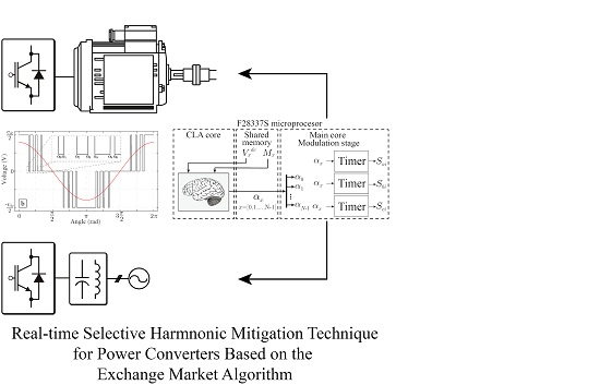
The performance of the proposed real-time EMA-based SHM application was tested in a laboratory prototype. In the experiments, a single-phase H-bridge converter (i.e., a three-level converter topology) was considered. However, as mentioned previously, the proposed EMA-based SHM method could be implemented in any three-phase three-level converter by just determining the switching signals corresponding to the obtained voltage levels. The experimental setup was based on the three-phase inverter stack from Semikron shown in
Figure 5a [
39] with DC-link voltage equal to 100 volts. The digital control platform used to implement the real-time SHM based on the EMA was the low-cost launchpad F28377S (
Figure 5b) equipped with a TMS320F28377S micro-controller by Texas Instruments [
40]. Among its features, the single C2000 200 MHz core plus one Control-Law Accelerator (CLA) running also at the same frequency were the most relevant items. In order to reduce the computational cost of the EMA-based SHM method, the C2000 core was in charge of the operation of the power converter, whereas the CLA co-processor was just devoted to implementing the EMA-based SHM algorithm, as is shown in
Figure 6. The use of multiple processors in the micro-controller board was a very well-suited solution to operate the power converter properly in actual industrial applications. The obtained execution time of one iteration of the EMA-based SHM strategy using this implementation strategy was
ms.
The SHM was tested considering seven switching angles, and two different sets of experiments were performed in order to demonstrate the proper performance of the proposed real-time implementation of the EMA-based SHM strategy. The first experiment considered the steady-state behavior, and the second one showed the good dynamic performance, showing a transient response.
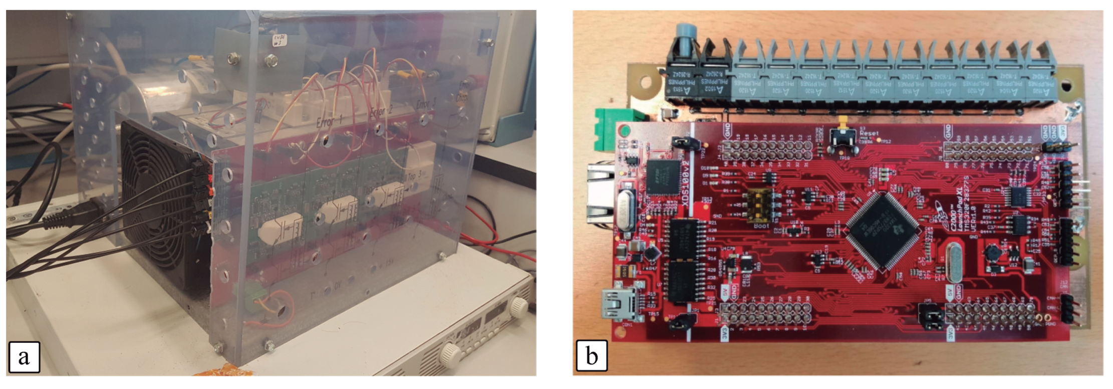
A stable steady-state EMA-based SHM solution could be achieved by operating the converter and running the EMA algorithm in the background up to achieving the solution convergence, obtaining a valid switching angle set solution, which happened after five fundamental frequency iterations approximately. As examples,
Figure 7a,b present the single-phase output voltage spectrum with modulation indexes equal to
and
, respectively. These steady-state output voltage spectra were obtained during power converter operation running the EMA-based SHM algorithm in the CLA processor. Notice that the presented results had triple harmonics, which are naturally eliminated in three-phase systems.
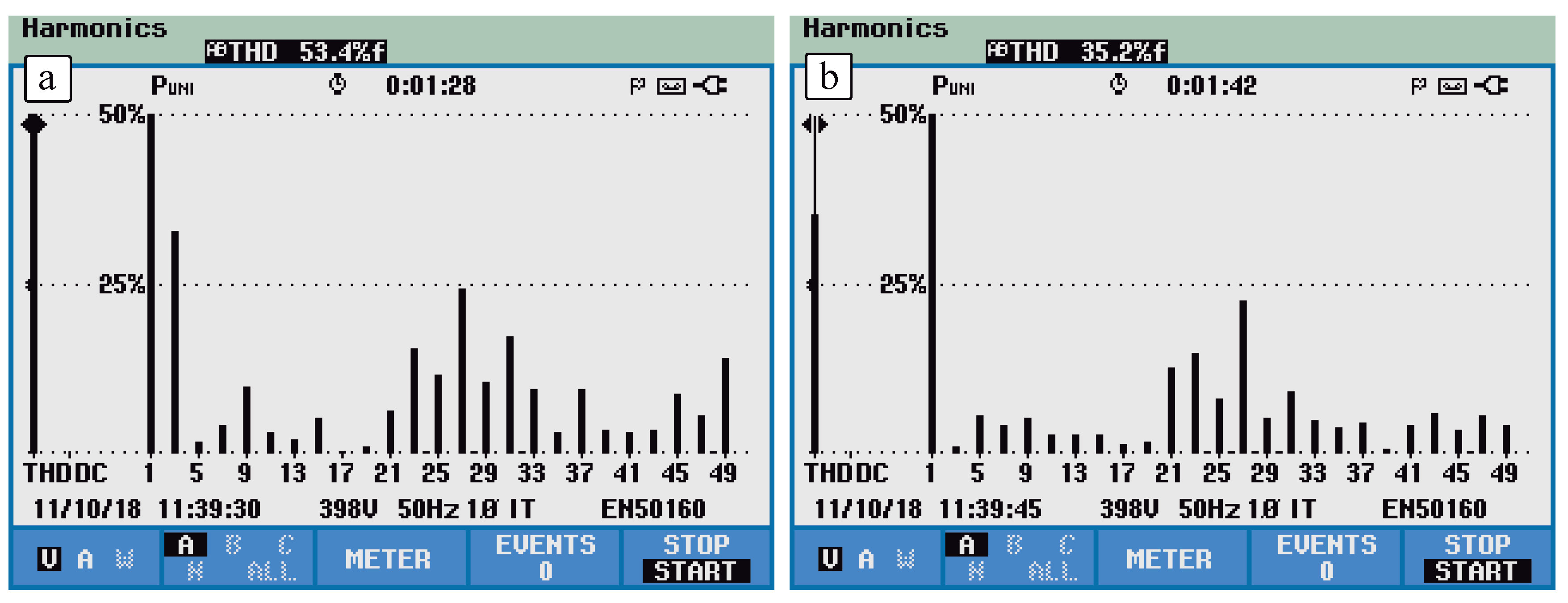
One relevant result to highlight about the EMA-based SHM algorithm performance was the evaluation of the steady-state solutions found by the method. For this reason, experimental tests were performed for a modulation index
from
to
, in steps of
. For each
value, the EMA-based SHM was executed, and
Figure 8 shows the obtained THD
(THD considering harmonics up to
order). It can be observed that in any case, THD
was always below the value obtained by applying the SHE method. In addition, in order to make a comparison of both methods considering each harmonic content,
Figure 9 shows the worst harmonic distortion values (highest value of the harmonic distortion of each component) obtained by the methods with the modulation index from
to
. It can be observed that considering seven switching angles, the EMA-based SHM obtained harmonic distortions below the grid code limits up to the
order (considering the grid codes summarized in
Table 1), while for such frequencies, SHE eliminated all distortion. For higher frequencies, the EMA-based SHM performance was better than using SHE because the corresponding harmonic distortion for each harmonic order was lower. This demonstrated that the EMA-based SHM performance was superior compared to conventional SHE, as expected.
The obtained results could be compared with the results obtained in [
10], where the SHM method was implemented off-line, achieving the switching angle set solutions applying the simulated annealing algorithm, which took a long time to converge. As can be observed from
Figure 9 and comparing with the corresponding results shown in [
10], the results from both approaches were very similar, but in the proposed method, the switching angle sets were determined in real time by applying the EMA.
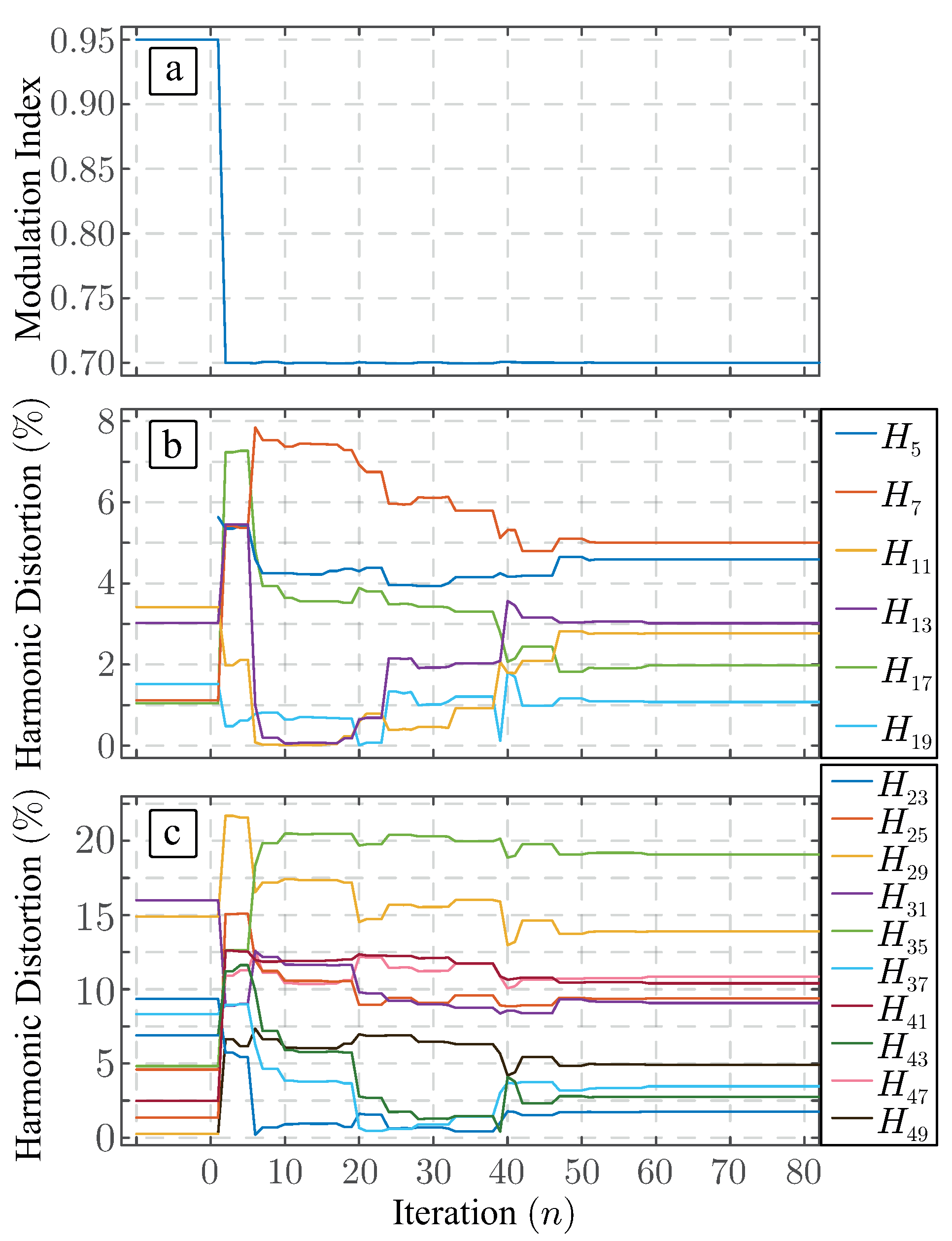
On the other hand, the application of the real-time EMA-based SHM strategy enabled the possibility to find dynamically a proper switching angle solution set during the power converter operation. In this way,
Figure 10 shows the power converter operation when the modulation index was changed from
to
. As the EMA-based SHM was running, the initial solution of the EMA was that obtained by the execution of the method considering
. As is shown in
Figure 10a, drawn by the continuous blue line, the EMA-based SHM method was continuously executed in the CLA processor in order to achieve the angle solution set convergence as soon as possible. Each fundamental period (20 ms), the C2000 processor applied the best solution obtained by the EMA-based SHM method, which is represented by the dashed red line. This information exchange was performed using a shared memory, which did not present any bottleneck. In addition, the steady-state output voltage harmonic spectrum for both operation points is shown in
Figure 10b. As was expected, the grid code up to the
order harmonic content was totally fulfilled. It is important to note that the EMA-based SHM solution was achieved only after five grid periods, highlighting the good performance of the real-time method to look for the switching angles. The detail of the dynamic performance of the EMA-based SHM method in this experiment is shown in
Figure 11. It can be observed that the modulation index was achieved in two iterations (
ms), and a steady-state behavior was achieved after 50 iterations (
ms). This result met the requirements of the grid codes EN50160, where the percentage of time that the converter had to meet harmonic distortion requirements was fixed, taking the measurements following the standard IEC61000-4-30 (which takes into account a low-pass filtered measurement of the last ten 50 Hz grid cycles).
6. Conclusions
Pre-programmed PWM methods (such as SHE and SHM) are based on the generation of the power converter output voltages by applying a set of reduced switching angles, which are determined to achieve high-quality harmonic response with reduced losses. SHM is one of these methods and takes into account grid codes and standards to minimize the output filter at the expense of greatly increasing the computational burden required to obtain the switching angles. This fact relegated SHM to be applied off-line and storing all the switching angle sets for all operational cases in large memories.
In this paper, for the first time to the authors’ knowledge, the SHM method was implemented in real time thanks to adapting the Exchange Market Algorithm (EMA) to look for a proper solution to achieve the SHM targets. The EMA is an optimization strategy that was initially designed to deal with financial transactions of valuable stocks between shareholders. In this work, the EMA was translated from the financial sector to power electronics to deal with the SHM problem. EMA considers the searching of the best SHM switching angles (the most valuable stocks) by evaluating non-linear equations and minimizing a cost function related to the harmonic spectrum performance.
It is important to note that the proposed implementation of the EMA-based SHM method could be applied to any three-level power converter topology (such as three full bridges (one per phase), neutral-point clamped, T-type). The method only needs a translation between the voltage level to be generated and the corresponding switching signals of the power devices.
The experimental results demonstrated that the EMA-based SHM method could be implemented in a low-cost control platform obtaining a real-time implementation of the method. The switching angles were obtained in a reduced number of grid periods, permitting taking into account the grid codes, improving as much as possible the output voltage quality depending on the number of switching angles. The steady-state EMA-based SHM results were superior to those obtained by the conventional SHE. In addition, the transient response of the EMA-based SHM method was also tested, showing a good performance. In both cases, steady-state and transient response, the EMA-based SHM method converged quickly and accurately, obtaining a good switching angle solution set in a reduced number of fundamental periods.

 ,
, 


