Article

Receding Horizon Control of Cooling Systems for Large-Size Uninterruptible Power Supply Based on a Metal-Air Battery System

1
Department of Mechanical and Aerospace Engineering, Seoul National University, Seoul 08826, Korea
2
Department of Electrical and Computer Engineering, Seoul National University, Seoul 08826, Korea
3
Department of Materials Science and Engineering, Seoul National University, Seoul 08826, Korea
4
Department of Mechanical Engineering, Dankook University, Gyeonggi-do 16890, Korea
5
Department of Mechanical Engineering, Hanyang University, Ansan 15588, Korea
*
Authors to whom correspondence should be addressed.
Energies 2020, 13(7), 1611; https://doi.org/10.3390/en13071611
Submission received: 10 March 2020 / Revised: 28 March 2020 / Accepted: 29 March 2020 / Published: 1 April 2020
(This article belongs to the Special Issue Power System Simulation, Control and Optimization)

Abstract

:
As application of electric energy have expanded, the uninterruptible power supply (UPS) concept has attracted considerable attention, and new UPS technologies have been developed. Despite the extensive research on the batteries for UPS, conventional batteries are still being used in large-scale UPS systems. However, lead-acid batteries, which are currently widely adopted in UPS, require frequent maintenance and are relatively expensive as compared with some other kinds of batteries, like metal-air batteries. In previous work, we designed a novel metal-air battery, with low cost and easy maintenance for large-scale UPS applications. An extensive analysis was performed to apply our metal-air battery to the hybrid UPS model. In this study, we focus on including an optimal control system for high battery performance. We developed an algorithm based on receding horizon control (RHC) for each fan of the cooling system. The algorithm reflects the operation properties of the metal-air battery so that it can supply power for a long time. We solved RHC by applying dynamic programming (DP) for a corresponding time. Different variables, such as current density, oxygen concentration, and temperature, were considered for the application of DP. Additionally, a 1.5-dimensional DP, which is used for solving the RHC, was developed using the state variables with high sensitivity and considering the battery characteristics. Because there is no other control variable during operation, only one control variable, the fan flow, was used, and the state variables were divided by section rather than a point. Thus, we not only developed a sub-optimal control strategy for the UPS but also found that fan control can improve the performance of metal-air batteries. The sub-optimal control strategy showed stable and 6–10% of improvement in UPS operating time based on the simulation.

1. Introduction

To date, many electrical storage systems (ESS), such as novel types of batteries and ultracapacitors, have been studied and applied to various systems. In particular, these batteries can improve the size or weight aspects of the storage system making it small-size and easy to move. Large size is required for ESS that optimize economical gain by charging/discharging large amounts of electrical energy and for uninterruptible power supplies (UPS) supporting large electrical systems in emergencies. UPS systems have studied by many researchers because UPS are essential for supporting electrical energy stability. Before being applied to practical commercialization, a UPS is developed and studied through modeling and simulation because of the scale [1,2,3].
However, UPS are often based on conventional batteries because of their economic convenience and reliability. Among the UPS systems, the hybrid UPS (H-UPS) combines an electrical storage system (ESS) with UPS, using lead-acid batteries as the source of DC voltage [4]. Currently, replacing the batteries with an ultracapacitor is not affordable, because of the price of the latter [5]. Lithium-ion batteries, which are mostly used as a secondary battery, are also costly. Additionally, the secondary batteries must be always activated when connected to the main power source. In this aspect, though reliable, lead-acid batteries require frequent maintenance, and therefore they are not affordable [6].
Therefore, UPS requires the introduction of new battery technologies, especially high-power UPSs (those of more than 10 kW), which are more challenging. Among the commercially available batteries, metal-air batteries have a high energy density and are inexpensive, when select metal electrodes are used. Thus, they are widely studied as primary or secondary batteries, and small-capacity metal-air batteries have already been commercialized as primary batteries [7,8]. However, they cannot be used as rechargeable batteries, because they support only a few recharging cycles. For this reason, metal-air batteries are suitable for high-power UPSs, which require high capacity and no recharge. In these systems, the initial standby time after triggering can be supplemented by hybridization with a small-sized lithium-ion battery. Thus, modeling and simulation of UPSs using metal-air batteries are needed for their commercialization. In a previous study, we developed UPS model using experimental cell data and theoretical analysis [9]. Simulation includes the controls for UPS and lithium-ion battery which is a secondary battery on standby during normal situation. However, after initial operation, when the primary battery, metal air battery, which is the main battery operates in earnest, only basic control using constant fan flow was applied.
Metal-air batteries are not widely used as energy storage devices in the industry. Thus, previous researches on controlling metal-air batteries have focused on determining their parameters or supplying stable energy [10,11,12]. However, the performance and lifespan of a battery is directly related to its thermal management system that controls the temperature of the battery [13,14,15]. Unlike other batteries for which the cooling system has already been studied, metal-air batteries have a significant limitations on air cooling because of its their consumption. Furthermore, previous studies have barely covered air-cooling of metal-air batteries because of their unusual properties. Although studies for cooling system control of metal-air batteries are fewer than for other batteries, control strategies for cooling systems of other batteries have been studied [16,17]. Especially, Zhan developed a rule-based control strategy for cooling PEM fuel cells in UPS systems [18].
This study devised a control strategy of air-cooling system for fuel supply using battery cell experimental data. As the optimal control strategy for a cooling system affects not only cooling but also oxygen supply, an overall performance improvement of the metal air battery could be expected. To do this, the detailed thermodynamics of metal-air battery among the UPS module were examined, and state variables were calculated for each cell. Because the studies for the UPS system based on metal-air battery are rare, detailed modeling of UPS system can be the first contribution. Though difficult, we applied the existing discrete dynamic programming (DP) algorithm, optimization theory, considering the characteristics of the metal-air battery. This is the second contribution of this paper and main contents.
The paper is structured in five sections. After this Introduction, Section 2 presents the UPS system modeling using prior research and thermodynamic models. Section 3 provides functions, parameters, and analytical theories to solve the main optimal problem for control modeling and simulation. Section 4 arrange the result of the simulation and compare that with other control strategies. Section 5 presents concluding remarks and the performance of the suggested control strategy.

2. UPS System Modeling

2.1. Prior Research

As previously mentioned, we developed a 64 kW UPS system using small-sized stacks of metal-air batteries in a previous study [9]. The research represents an important experimental trial to develop a UPS system based on metal-air batteries. The major point of the prior research was to determine the entire composition of the system and a hybrid system using lithium-ion battery. Thermodynamic and electromechanical analyses were performed assuming that the properties of the cells in each module of the UPS system are uniform:
T 1 = T 2 = = T n
C p m o d u l e = C p case + C p e l e c t r o l y t e + k = 1 n C p c e l l , k
where T is the temperature, C p is the heat capacity, and n is the number of cells in a module. The parameters of the previous UPS model were also used in this study. Table 1 shows the parameters of the iterative simulation and mechanical calculation used. A total of 20 fans that supply oxygen and cool the module were located at the 20 inlet, and 20 fans at outlet. The flow rate of these fans was constant value in the previous study, i.e.:
Q 1 t = Q N 2 , 1 t + Q O 2 , 1 t = Q 2 t = = Q m t = c o n s t
where Q m t is the flow rate at time t on m t h fan, Q N 2 , m t , Q O 2 , m t is the flow rate of gas except oxygen, and the flow rate of oxygen gas.
The parameters were designed to satisfy the required specification of up to 2 h runtime under maximum electrical load with a simple constant flow control. The 2 h runtime was the minimum required specification of the UPS until the main source is connected again. Though the simple constant flow control showed good performance under static load power, it was not optimized for different environments like changing electrical loads. Therefore, it did not show stable control performance in this case, because it did not meet the electrical load and boundary conditions of a metal-air battery.

2.2. Thermodynamic Model

To optimize the previous control strategy for a metal-air battery-based UPS, the thermal effect of each cell was modeled for a system of 180 cells per module. The heat in each cell was modeled using the Gibbs potential energy and the voltage from the cell as:
Q h e a t ( t k ) = I c e l l ( t k ) ( G z i n c V c e l l ( x ( t k ) ) )
where Q h e a t is the heat, I c e l l is the current in the cell, G z i n c is the Gibbs potential of the zinc oxide reaction, V c e l l is the voltage of the cell, and t k is the time at step k .
The cooling effect and performance of the fans in each cell were also divided to simulate along with the units. To calculate the heat coefficient on a plate for natural convection, we used the following equations:
N u = { 0.825 + 0.387 R a 1 6 [ 1 + ( 0.492 P r ) 9.16 ] 8 27 } 2
where N u is the Nusselt number, R a is the Rayleigh number for natural convection, and P r is the Prandtl number, and:
C h e a t = K a i r N u L * ,     L * = L H × L W 2 ( L H + L W )
where C h e a t is the heat coefficient of the plate, K a i r is the thermal conductivity of the air, and L H and L W are the height and width of the plate, respectively.
A diagram of the stack structure and thermal effect is presented in Figure 1.
The thermodynamics of each cell in the UPS module described in Figure 1 are modeled by the following equations:
Q c a s e = k = 1 e n d ( C c e i l , k · A c e i l , k · Δ T c e i l , k + C f l o o r , k · A f l o o r , k · Δ T f l o o r , k ) + C s i d e , 1 · A s i d e , 1 · Δ T s i d e , 1 + C s i d e , e n d · A s i d e , e n d · Δ T s i d e , e n d
where C x , k and A x , k are the thermal conductivity and surface area of area x in k th cell, respectively; and:
T k , t = T k , t 1 + d d T ( Q h e a t ,   k Q c a s e , k Q a i r , k Q c o n d u c t   n e a r ,   k ) · Δ T    
Q c o n d u c t   n e a r , k = Q c o n d u c t , k 1 + Q c o n d u c t , k + 1
where T k , t is the temperature of the k th cell at time t , Q c e l l , k is the heat of the chemical reaction, Q c a s e , k is the (negative) heat of the natural cooling from the aluminum case, Q a i r , k is the negative heat forced by air-cooling, and Q c o n d u c t   n e a r , k is the negative heat caused by conduction to the neighboring cell.

2.3. UPS Simulation and Fan Control

Many UPS control studies have been conducted on the control of the circuit-level inverter, input, and output current to stabilize the voltage, e.g., [19,20,21]. Here, we assumed a stable electrical load and supply from the UPS model to the battery model, because our metal-air battery model focused on the power supply at the stack-level and on the operation time for a given electrical load. The main target of this study is the fan flow, which can be controlled during operation to improve the performance which includes operating time and stability of the UPS model. The system used in this study consists of stacked modules, which were modeled using the experimental data of the cell units. Thus, the system is a nonlinear discrete state-space model that can be defined simply as:
x ( t + 1 ) = f ( x ( t ) , u ( t ) ) , y ( t ) = g ( x ( t ) ) .     t = 1 ,   2 ,   3 ,   ,   t e n d
Here, x ( t ) is the state, y ( t ) is the output, u ( t ) is the control input, f is the modeled system function computing the states of next step by the state of prior step, and g is the modeled system function computing the output by the state of this step.
The UPS model consists of a hybrid system that supplies stable electrical power. A lithium-ion battery that operates only initially is always connected to the main power system. A metal-air battery operates as the main source after it starts generating electric energy stably. Here, we developed a strategy to control the module containing the metal-air battery. The metal-air battery module is modeled by electrochemical formulas obtained from experimental data. The formula used to calculate the voltage in the cell is:
V c e l l ( t k ) = V s o c ( S O C t k ) × P V x 1 ( x 1 ( t k ) ) × P V x 2 ( x 2 ( t k ) ) × P V x 3 ( x 3 ( t k ) )
where V c e l l is the voltage of the cell, V s o c is the voltage output by the state-of-charge,   S O C t k is the S O C on the time step t k , and P V x k is the voltage fraction in x k . Because the variables of the experiment for acquiring the cell data were reduced to three, we set only three state variables to calculate the voltage of the cell.

3. Control Modeling and Simulation

3.1. The Conceptual Framework

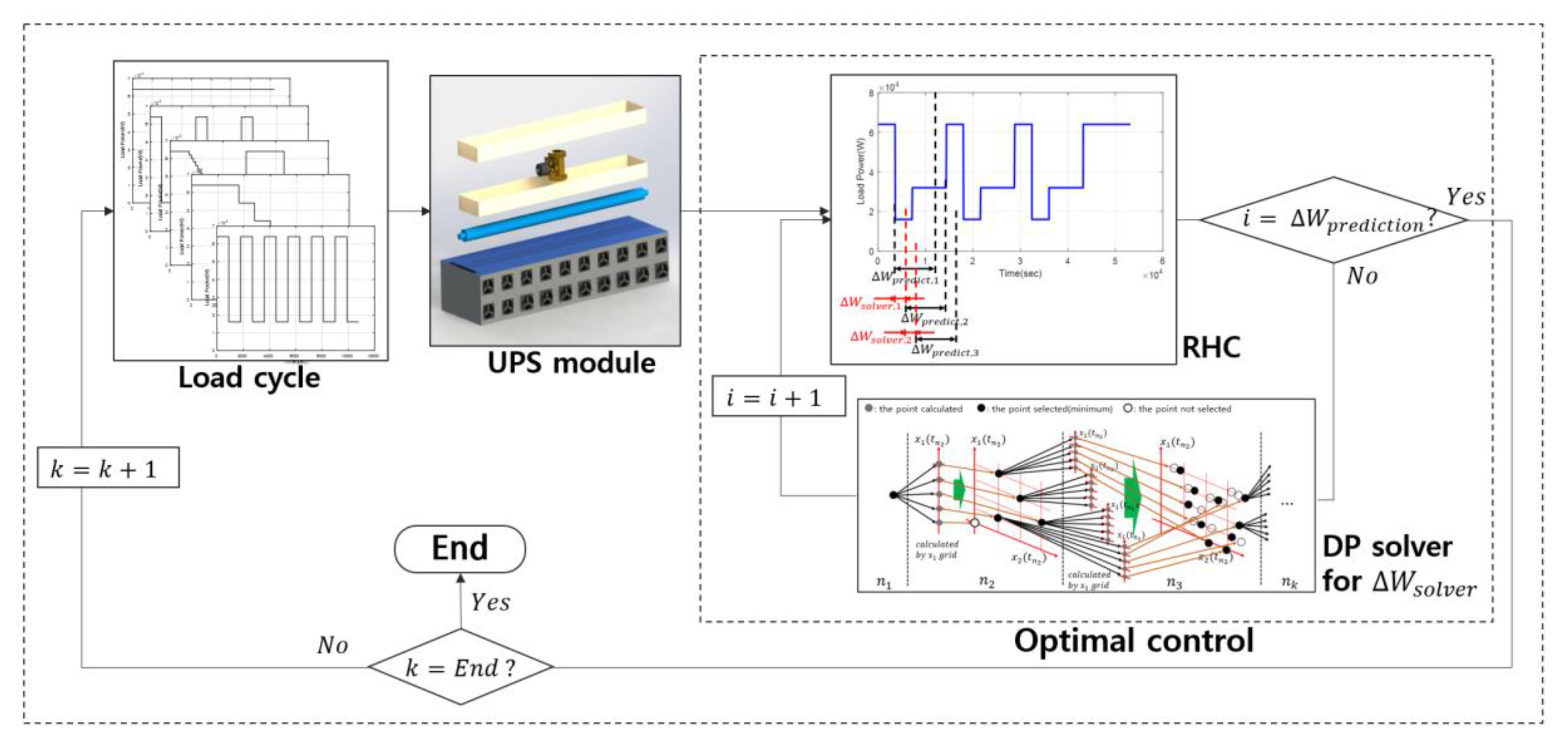
As mentioned above, the target of this research is the optimal control strategy of an UPS system based on metal-air battery. For simulating the system, the model is developed using iteration for time step using discrete calculation. The schematic diagram for controlling the UPS module is shown in Figure 2. The modeling of whole system is coded in Matlab, which is a commercial program from Mathworks (Natick, Massachusetts, USA).

3.2. Receding Horizon Control

The receding horizon control (RHC), also known as moving horizon control, is a feedback control strategy for nonlinear or linear plants with input and state constraints [22]. RHC is suitable for slow nonlinear systems, such as chemical processes, that can be solved sequentially [23]. Many studies have investigated UPS using a model predictive control (MPC), which is another name for RHC [24,25].
The typical electrical load for an UPS can be predicted with a few minutes of advance notice. However, predicting the electrical load continuously is unrealistic, because the conditions of environment of the system and the UPS model can change. Thus, it is common to adjust the system loads supplied by the UPS model according to the pre-scenario or situation of the UPS model, so that the electrical load can be predicted for few minutes from the time of operation. Because of this, RHC is applied to the optimal control proposed in this study. Usually, RHC analyzes the model in the prediction window using linear problem (LP) or a quadratic problem (QP). However, the UPS model of this study is composed of tables of the cell data. Therefore, the key to optimal control is to solve the target function within the prediction window. The target applied to the RHC prediction is the electrical load of the UPS in the system, and the state prediction can be expressed as:
x ( t k + 1 + i | t k ) = f ( x ( t k + 1 | t k ) , u ( t k + i | t k ) )
y ( t k + i | t k ) = g ( x ( t k + i | t k ) )
where x ( t k + i | t k ) is the state value of x predicted at time t k + i using the information available at time t k , x ( t k ) is the state at time t k , y ( t k ) is the cost value at time t k , and f , g are the functions for state and cost value, respectively.
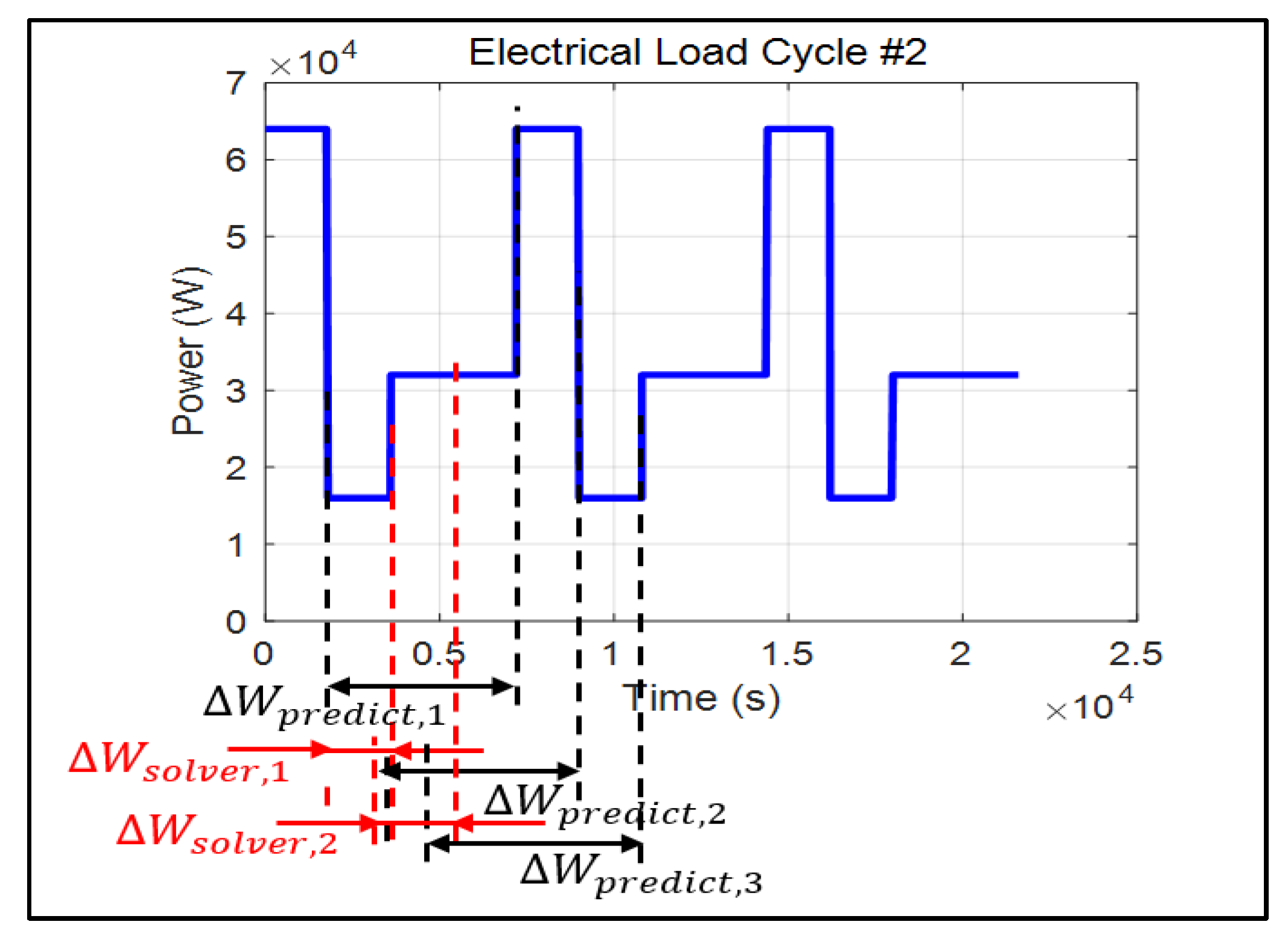
The range of i (prediction window) at step s is Δ W p r e d i c t , s . As seen in Figure 3, the range of optimal control in Δ W p r e d i c t , s is set to Δ W s o l v e r , s (i.e., the solver window at step s ) as:
J s , s + N s i m u l = t k t k + Δ W s o l v e r g ( x ( t | t k ) , u ( t | t k ) , t | t k ) d t ,     ( N s i m u l = Δ W s o l v e r Δ t s i m u l   )
where J s , s + N s i m u l is the cost function of s t h iteration. The solver means one iteration to solve the optimal control values under state variables.
Here, the cost function to be minimized for the metal-air battery-based UPS, J s ,   s + N s i m u l , is the metal (zinc) consumption. In state variable of x in Equation (12), the temperature that has a major influence on the performance was included first. The equation to calculate the optimal control in the Δ W p r e d i c t , k is:
u k * = a r g min u { t k t k + Δ W p r e d i c t , k g ( x ( t | t k ) , u ( t | t k ) , t | t k ) d t } ,     ( v m i n u v m a x )
Here, u k * is the optimal control at step k , v m i n is the minimum fan flow, and v m a x its maximum.
Although the optimal control should be calculated in the Δ W p r e d i c t , k , only the optimal control in Δ W s o l v e r , k was applied to the cost function, because in RHC the optimal control should be updated for each Δ W s o l v e r . The cost result and optimal cost are calculated as:
J R H C = k = 1 N t o t a l J k * = k = 1 N t o t a l t k t k + Δ W s o l v e r g ( x ( t ) , u k * ( t ) , t ) d t ,   N t o t a l = T o t a l   t i m e Δ W s o l v e r
where J R H C is the RHC cost result of the whole simulation, and J k * is the optimal cost at step k . The prediction window covers the electrical system load needed to operate the RHC for a few minutes. After the UPS starts its operation, it is necessary to estimate the load and control the input in the Δ W p r e d i c t , k .

3.3. Dynamic Programming

The RHC developed in this study cannot be solved mathematically by merely using a discrete variable matrix. In the window of each step of the RHC, J k * can be calculated by finding u k * ( t ) using DP, which is a global optimization theory. This control method based on the RHC prediction is similar to the ‘Look-ahead DP’ [26,27].
Applying the time step of the UPS chemical simulation, Δ t s i m u l , to Equation (14), this becomes the discrete equation:
J s , s + N s i m u l = m = 1 N s i m u l g ( x ( t m | t k ) , u ( t m | t k ) , t m | t k ) · Δ t s i m u l
Although the simulation of the battery differs for each model, it cannot be solved in the grid at each time step. Then, in DP, the state of the battery has to be calculated for each temperature difference ( Δ T ) , which is less than 0.001 °C/s. Though the range of Δ T varies according to the temperature of the cell, if the total difference is divided in the entire range, computing cost increases exponentially ( Δ T t o t a l / Δ T 55,000 ). Therefore, the range of each state is calculated for each time step in the prediction window, and state x k is assigned according to this. Thus, the DP step is set separately from the time step of the UPS chemical simulation, Δ t s i m u l , according to Δ t D P as:
N D P = Δ W p r e d i c t i o n Δ t D P ,             N R H C = Δ W s o l v e r Δ t D P
Then, Equation (17) can be represented as a recursive relation using Δ t D P :
J s , s + N s i m u l * ( x ( t k ) ) = m i n { g ( x ( t s | t k ) , u ( t s | t k ) , t s | t k ) · Δ t D P + J s + 1 , s + N s i m u l * ( x ( t k + 1 ) ) }
where J s , y * is the optimal cost calculated from t s to t y , and s = 1 , 2 , ,   N D P . This recursive relation can conclude minimum cost value using final time t e n d and backward calculation from J s + N s i m u l 1 , s + N s i m u l * ( x ( t e n d ) ) .Finally, using Equations (18) and (19), Equation (16) becomes Equation (20), which represents the discrete-type cost result:
J R H C = k = 1 N t o t a l J k * = k = 1 N t o t a l p = 1 N R H C g ( x ( t p ) , u k * ( t p ) , t ) · Δ t D P

3.4. Solver Based on 1.5-Dimensional DP

In general, an n-dimensional DP has n states and n control variables. However, in the model developed in this study, there is only one control variable, the fan flow. As shown in the following Equations (21) and (22), there are at least three states for which the data maps are shown in Figure 4:
V ( t ) = h ( I J ( t ) , ρ ( t ) , T ( t ) , S O C ( t ) )
Z n c o n s u m p , t 1 = t 0 t 1 q ( V ( t ) , I J ( t ) , ρ ( t ) , T ( t ) , S O C ( t ) ) d t
Here, V ( t ) is the output voltage, I J ( t ) is the current density, ρ ( t ) is the oxygen density, T ( t ) is the temperature, S O C ( t ) is the state of charge, Z n c o n s u m p , t 1 is the Zn consumption until time t 1 , h is the modeled system functions to calculate output voltage using cell experimental data, and q is the modeled functions to calculate metal consumption using cell experimental data.
Because UPS is a chemical model that uses batteries, the variables I J ( t ) , ρ ( t ) , and T ( t ) are interrelated states at each moment. Their values depend on each previous state and the control variable. The sensitivity of the states, i.e., their change in a single step, determines which of the states is the reference for DP.
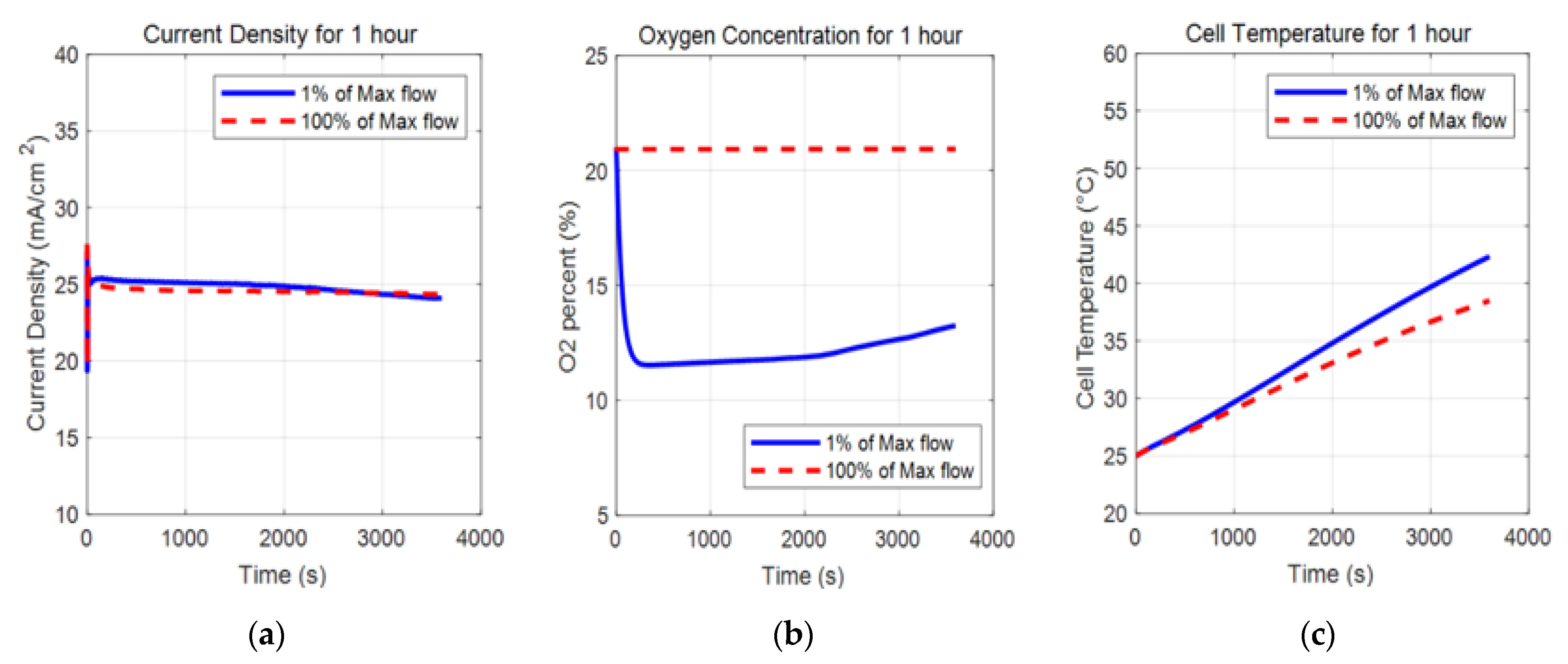
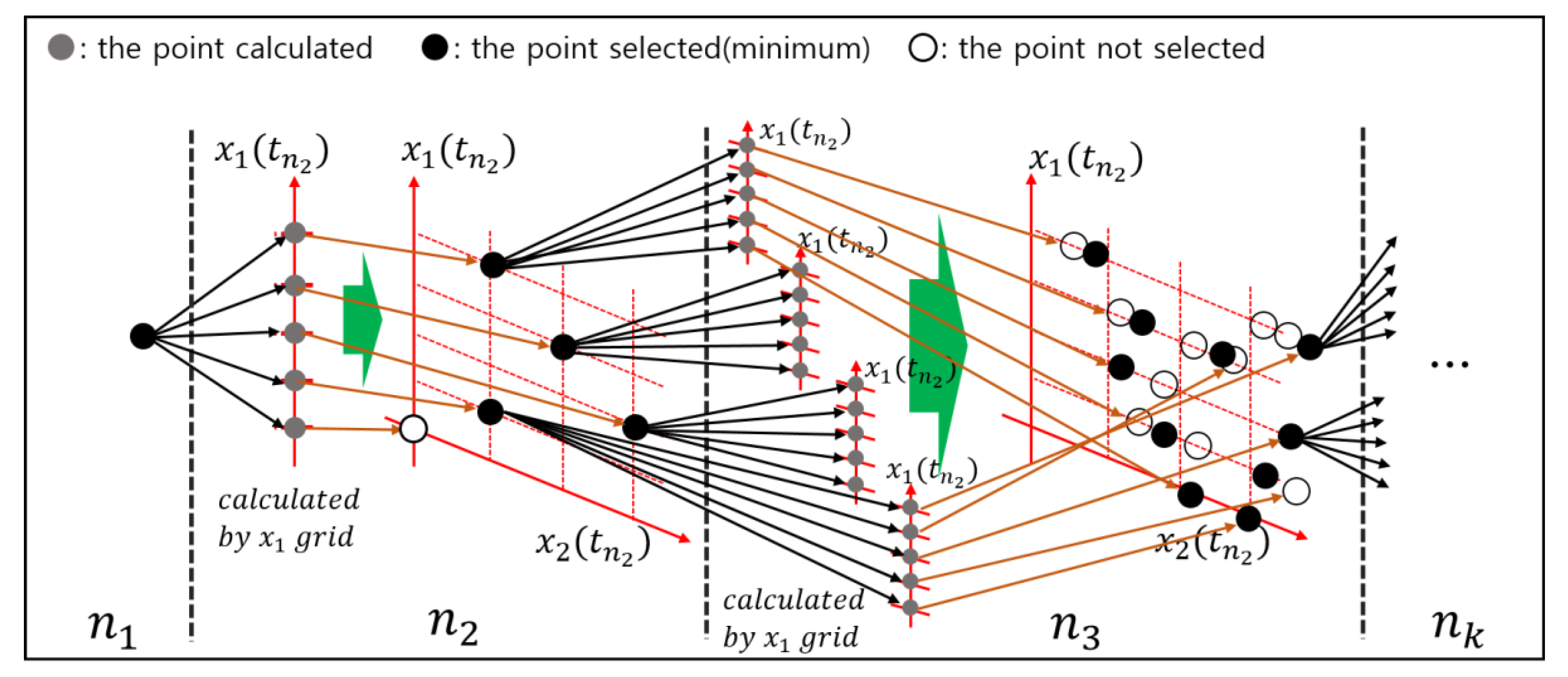
When the state variables that directly affect the output voltage are simulated for 3600 s, at constant load power and with the minimum and maximum fan flow, the current density I J ( t ) changes only slightly, as seen in Figure 5. Therefore, the cell temperature T ( t ) and oxygen concentration ρ ( t ) were chosen as the state variables for DP. As discussed, the cell temperature was calculated by distinguishing the time variables Δ t s i m u l and Δ t D P , and considering that the state of the previous step has a major influence on the next one. However, the oxygen concentration is very sensitive to the states of each step, which depend on the fan flow. Thus, as DP proceeds, the target grid of the oxygen concentration is sparsely split, because this is determined when the cell temperature is applied to the grid by a control input. Therefore, the optimal x 2 was selected among a target region instead of the target point to solve the 1.5-dimensional DP structure:
x 1 , t m + 1 = f 1 ( x t m , u t m ) ,     u m = f 1 ( x 1 , t m + 1 , x t m ) ,     x 2 , t m + 1 = f 2 ( x t m , u t m )
x 2 , t m + 1 = f 2 ( x t m , f 1 ( x 1 , t m + 1 , x t m ) ) ,     x t m = ( x 1 , t m ,   x 2 , t m ) .  
Here, f 1 is a reverse function for acquiring the control variable u m using the 1st state variable at time t m + 1 , x 1 , t m + 1 and the state variables at time t m , x t m . The next step, the 2nd state variable at time t m + 1 , x 2 , t m + 1 , can be obtained from x 1 , t m + 1 (that of the next step) and x t m (the state variables of the this step). This recursive process make us calculate the optimal control by selecting the minimum points as path in J s , s + N s i m u l * among each region grid for the next DP step, as shown in Equation (19). This can be expressed as in Figure 6.
The experimental UPS data show that, below 60 °C and within the operational boundary conditions, the zinc consumption is higher for lower temperatures. This means that, when the difference between the lowest and highest temperature in the cells is higher than 10 °C, or the highest temperature is lower than 60 °C, the largest zinc consumption is that of the cell located at the end of the module.
When inverting the control input for the target state T , as in Equation (24), the metal-air battery model cannot calculate backward accurately, because all variables change. Therefore, the target T was calculated after obtaining the minimum and maximum cell temperature in the last step of the solve window, ( k + Δ W p r e d i c t i o n ).
Because of these approximations, the algorithm is not perfectly and globally optimal, though reasonably optimal values are used.

3.5. Electrical Load Cycle

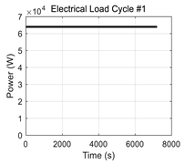
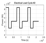
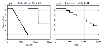
A basic electrical load cycle having the performance required by existing UPSs is shown as the first graph in Table 2. The power required was revised by increasing the simulation time from 7200 to 9000 s to evaluate the performance of the UPS control (cycle #1). Additionally, because the load power of the cycle is constant and simple, four more scenarios (cycle #2–#5) of operation time from 2 to 4 h were included in the simulation. These cycles are shown in Table 2.

4. Results

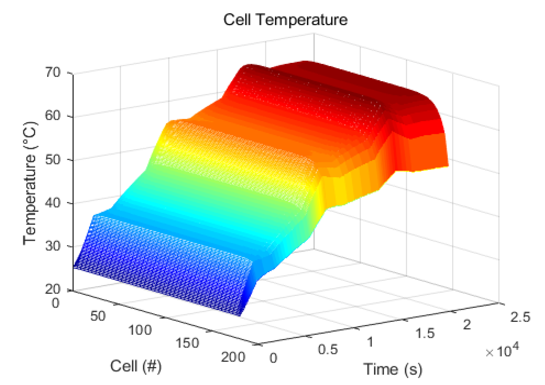
We experimented the proposed RHC algorithm using two-parameter settings. RHC #1 used Δ W solver = 10 and Δ W prediction = 200, and RHC #2 used Δ W solver = 20 and Δ W prediction = 100. We also simulated the UPS model with full DP control which assumes that we know the entire electrical load cycle. This control means globally optimal potential of the UPS model for comparison. In total the simulations were run controlling the fan by RHC, DP control, and constant fan flow. Electrical load cycle #2, which used the DP control, showed a distinct difference, and the resulting cell temperature of the entire module is shown in Figure 7.
As mentioned in Section 3.5, the temperature of the cell at the end of the module is significantly lower than that of the other cells during the entire simulation time. This is caused by the natural air-cooling of the module. Additionally, the temperature difference increases with time. By comparing with electrical load cycle #2 of Figure 6, it can also be seen that the temperature increases rapidly because of the large heat generated when the electrical load increases rapidly.
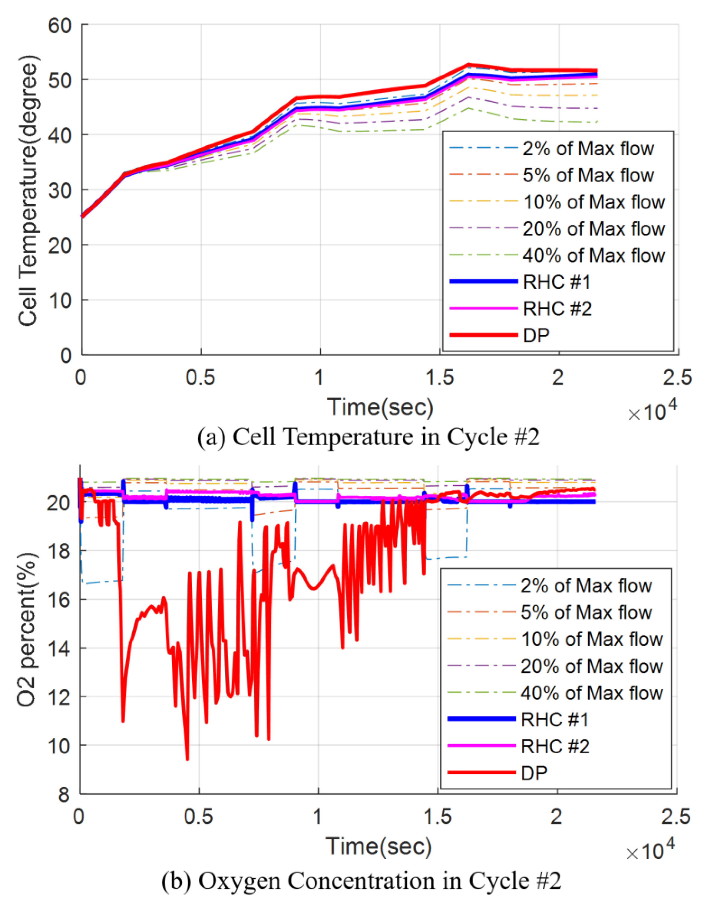
To compare the different controls, i.e., RHC #1, RHC #2, DP, and constant fan flow (1%, 2%, …, 100% of the maximum fan flow), the state variables based on electrical load cycle #2 were used, leading to the result shown in Figure 8.
The cell temperature reported in Figure 8a indicates that the influence of the fan flow is not significant at first. However, it increases accumulating over time, resulting in a large difference between the controls. In the case of the oxygen concentration of Figure 8b, the effect of electrical load cycle #2 of Figure 6 is critical, because the oxygen concentration by all controls except DP vibrates under electrical load. Particularly in the case of the DP control, the optimal oxygen concentration of the whole cycle drops below 10%. Additionally, the constant fan flow control shows that the oxygen concentration increases gradually as the oxygen consumption decreases with increasing temperature. However, in the case of RHC, the initial oxygen concentration can be maintained through the cycle despite the temperature difference. Because the oxygen concentration hardly drops within a single prediction window, the locally optimal path of the control input is near the high oxygen concentration. The controls which maintained oxygen concentration as high unnecessarily using much electric energy. These trends of the variables by RHC will be similar in different situation because RHC has characteristic to find local optimal regardless of condition of the system and circumstances.
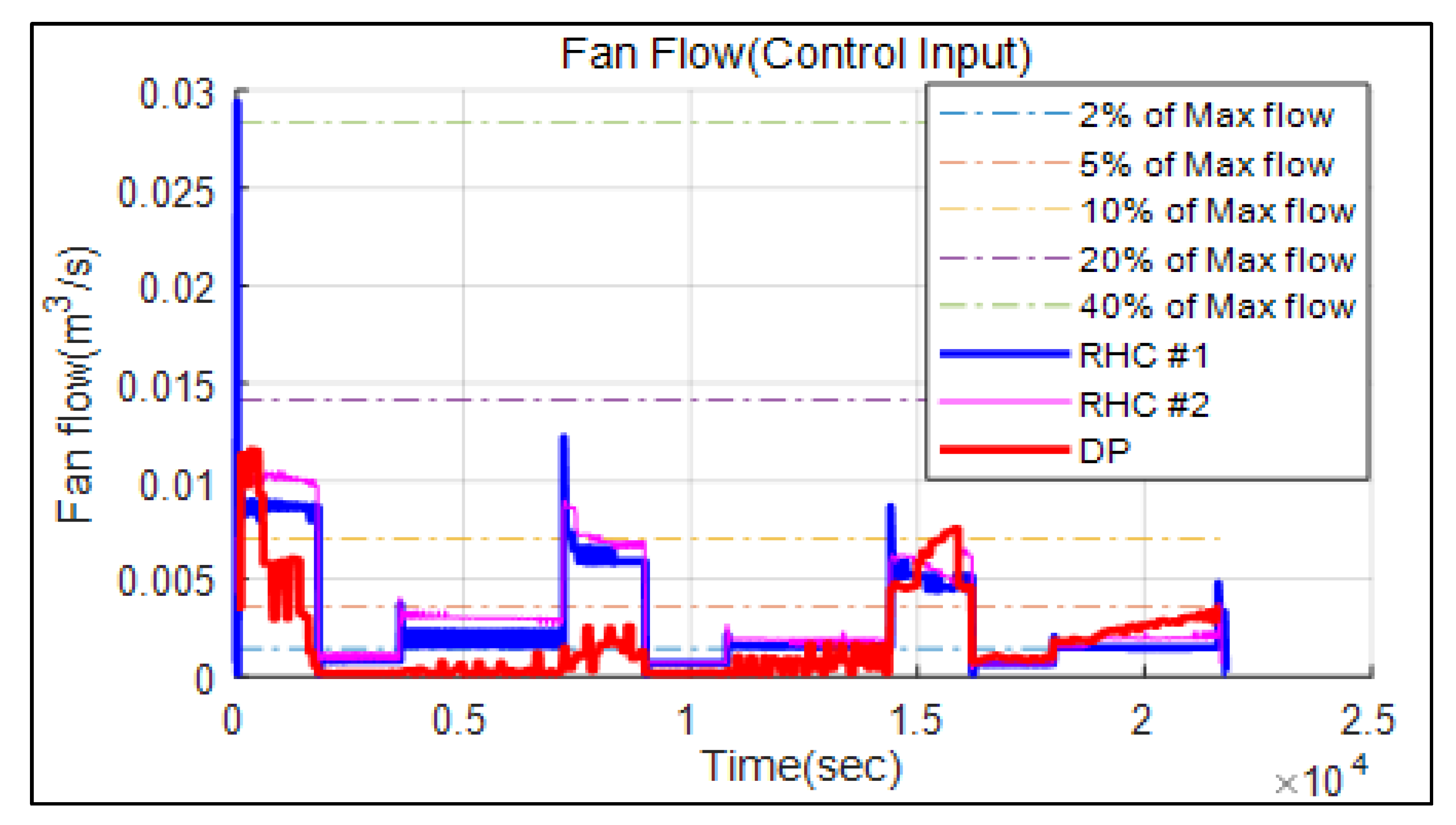
Looking at the fan flow for each control of Figure 9, it is seen that, in RHC, it is different from the DP control, though it gradually follows DP one with a time because of the optimal algorithm. Additionally, the fan flow of the RHC #1 control tends to be lower than that of RHC #2. When Δ W p r e d i c t and Δ W s o l v e r were respectively increased and decreased (RHC #2 → RHC #1), we found that this control input is better than the DP one. This is usually attributed to low flow in the boundary condition.
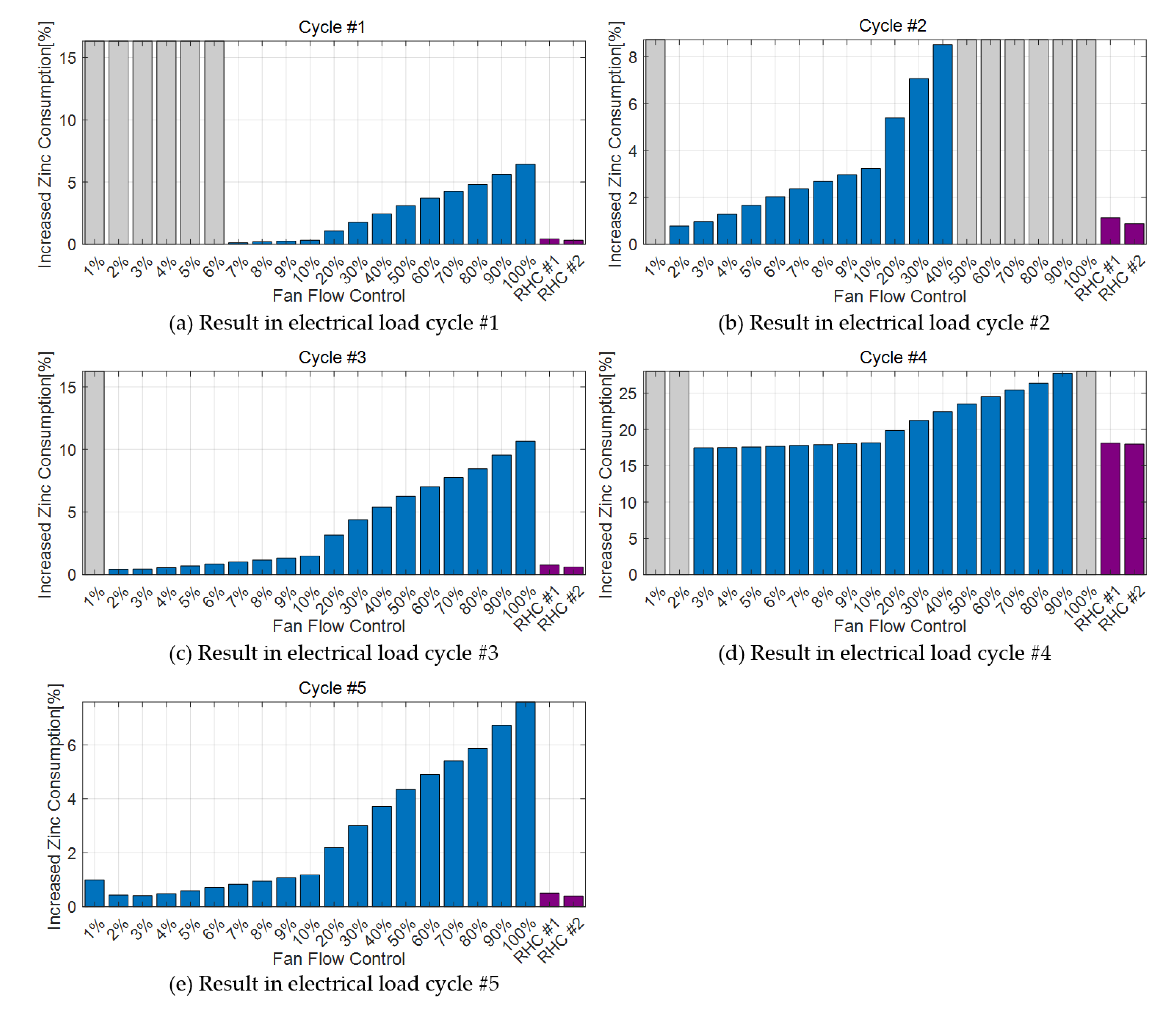
The zinc consumption in all electrical load cycles is shown in Figure 10, using consumption of DP as reference (100%). Here, a grey bar indicates that the simulation stopped because a boundary condition, such as the state-of-charge of the battery, temperature, and oxygen concentration, was met before the total simulation time had passed. The RHC proposed in this study is represented in purple. The results confirm that the RHC control is effective in reducing the zinc consumption of metal-air battery-based UPSs increasing its operation time. In particular, RHC #1 showed stable and excellent performance, in contrast to other constant fan flow controls that fail or consume excessive zinc. Compared to the low-speed flow (that of less than 1–10% of the maximum fan flow), the zinc consumption of RHC #1 is not lower. However, in the case of the low-speed flows, the battery failed because of a poor cooling forced by the fans. Instead, compared with the other controls, RHC #1 displayed a maximum 6–10% difference in zinc consumption.
In most cycles, the zinc consumption is lower for weaker fan flow, though it is seldom very high in these cases either. However, because the simulation time was determined from the available operation time, all of the zinc metal was consumed, as indicated by the gray bars.
RHC #2 showed a slightly lower performance than RHC #1. However, it displayed a relatively low computing cost, approximately 1/5 of the original cost of RHC #1. As a matter of fact, RHC #1 cannot be used for real-time control because its simulation time is 4–5 times higher in a generic PC (i7-4790 CPU, 16GB RAM). In contrast, RHC #2, which needs a longer prediction range, needs a simulation time similar to the actual UPS running time. Thus, in principle, applying RHC #2 as real-time control in UPS is possible. If the current UPS model is simplified through data mapping, or the RHC control algorithm is optimized further, real-time control can be applied in industry. Additionally, the scenario of the facilities connected to the UPS in the event of a main power outage can be determined. In this case, the DP algorithm can be applied to increase the performance of the UPS as the potential with the predicted overall electrical load cycle.

5. Conclusions

In this work, a study to replace the existing lead-acid battery UPS by applying a metal-air battery was extended. The thermodynamic model is refined by simulating each cell in the stack module. Based on this, we proposed an optimizing algorithm that controls the flow of the fan that blows air to each cell in the module, decreasing its temperature. Because metal-air batteries use oxygen from the air as a fuel, it is difficult to study the correlation between the flow and the battery performance. Additionally, because the battery model is based on a chemical model, it is challenging to apply DP, which is a theory calculated with discrete points. To solve this problem, we developed a 1.5-dimensional DP suitable for zinc-air batteries.
An RHC model using DP is proposed to find the optimal cost function in the Δ W p r e d i c t i o n window, which was estimated in the range of several tens of seconds of electrical load. The load power of the proposed model is more stable than that of the existing control strategies constantly controlling the fans, and it shows excellent performance in terms of overall zinc consumption. Although not globally optimal, appropriate control inputs can be calculated and applied to the oxygen concentration and temperature of each step.

Author Contributions

“Conceptualization, B.G. and G.-Y.C.; methodology, B.G.; software, H.L., D.S.; validation, S.L., S.Y. and S.K.P.; formal analysis, H.L.; investigation, C.K.; resources, S.Y.; data curation, S.K.P.; writing—original draft preparation, B.G.; writing—review and editing, N.K.; supervision, S.W.C. All authors have read and agreed to the published version of the manuscript.”

Funding

“This research received no external funding.”

Acknowledgments

This work was supported by the Technology Innovation Program (20002762, Development of RDE DB and Application Source Technology for Improvement of Real Road CO2 and Particulate Matter) funded by the Ministry of Trade, Industry and Energy (MOTIE, Korea), and partially supported by the National Research Foundation of Korea (NRF) grant funded by the Korea government (Ministry of Science and ICT) (No. NRF-2019R1A4A1025848, No. NRF-2019R1G1A1100393).

Conflicts of Interest

“The authors declare no conflict of interest.”

References

  1. Chew, C.; Rama, S.; Kondapalli, R. Optimization ( Genetic Algorithm ) of dc-dc converter for uninterruptible power supply applications | S S r-. Int. J. Pure Appl. Math. 2018, 118, 1530–1535. [Google Scholar]
  2. Narvaez, D.I.; Villalva, M.G. Modeling and control strategy of a single-phase uninterruptible power supply (UPS). In Proceedings of the 2015 IEEE PES Innovative Smart Grid Technologies Latin America (ISGT LATAM), Montevideo, Uruguay, 5–7 October 2015; pp. 355–360. [Google Scholar]
  3. Lahyani, A.; Venet, P.; Guermazi, A.; Troudi, A. Battery/Supercapacitors combination in uninterruptible power supply (UPS). IEEE Trans. Power Electron. 2013, 28, 1509–1522. [Google Scholar] [CrossRef]
  4. Chlodnicki, Z.; Koczara, W.; Al-Khayat, N. Hybrid UPS based on supercapacitor energy storage and adjustable speed generator. In Proceedings of the 2007 Compatibility in Power Electronics, Gdansk, Poland, 29 May–1 June 2007; Volume XIV, pp. 13–24. [Google Scholar]
  5. Mallika, S.; Kumar, R.S. Review on ultracapacitor- battery interface for energy management system. Int. J. Eng. Technol. 2011, 3, 37–43. [Google Scholar]
  6. Han, X.; Ji, T.; Zhao, Z.; Zhang, H. Economic evaluation of batteries planning in energy storage power stations for load shifting. Renew. Energy 2015, 78, 643–647. [Google Scholar] [CrossRef]
  7. Linden, D.; Reddy, T.B. Handbook of Batteries, 3rd ed.; McGraw-Hill Professional: New York, NY, USA, 2002. [Google Scholar]
  8. Lee, C.W.; Sathiyanarayanan, K.; Eom, S.W.; Kim, H.S.; Yun, M.S. Effect of additives on the electrochemical behaviour of zinc anodes for zinc/air fuel cells. J. Power Sources 2006, 160, 161–164. [Google Scholar] [CrossRef]
  9. Gu, B.; Yoon, S.H.; Park, S.K.; Byun, S.; Cha, S.W. A study on the application of metal–air battery to large size uninterruptible power supply with a hybrid system. JMST Adv. 2019, 1, 181–190. [Google Scholar] [CrossRef] [Green Version]
  10. Lee, J.; Yim, C.; Lee, D.W.; Park, S.S. Manufacturing and characterization of physically modified aluminum anodes based air battery with electrolyte circulation. Int. J. Precis. Eng. Manuf. Green Technol. 2017, 4, 53–57. [Google Scholar] [CrossRef]
  11. Wang, K.; Pei, P.; Wang, Y.; Liao, C.; Wang, W.; Huang, S. Advanced rechargeable zinc-air battery with parameter optimization. Appl. Energy 2018, 225, 848–856. [Google Scholar] [CrossRef]
  12. Xiao, Y.; Jing, R.; Song, H.; Zhu, N.; Yang, H. Design and experiment on zinc-air battery continuous power controller based on microcontroller. Chem. Eng. Trans. 2016, 51, 91–96. [Google Scholar]
  13. Li, Z.Z.; Cheng, T.H.; Xuan, D.J.; Ren, M.; Shen, G.Y.; de Shen, Y. Optimal design for cooling system of batteries using DOE and RSM. Int. J. Precis. Eng. Manuf. 2012, 13, 1641–1645. [Google Scholar] [CrossRef]
  14. Sabbah, R.; Kizilel, R.; Selman, J.R.; Al-Hallaj, S. Active (air-cooled) vs. passive (phase change material) thermal management of high power lithium-ion packs: Limitation of temperature rise and uniformity of temperature distribution. J. Power Sources 2008, 182, 630–638. [Google Scholar] [CrossRef]
  15. Ling, Z.; Wang, F.; Fang, X.; Gao, X.; Zhang, Z. A hybrid thermal management system for lithium ion batteries combining phase change materials with forced-air cooling. Appl. Energy 2015, 148, 403–409. [Google Scholar] [CrossRef] [Green Version]
  16. Xie, J.; Ge, Z.; Zang, M.; Wang, S. Structural optimization of lithium-ion battery pack with forced air cooling system. Appl. Therm. Eng. 2017, 126, 583–593. [Google Scholar] [CrossRef]
  17. Wang, Y.X.; Qin, F.F.; Ou, K.; Kim, Y.B. Temperature control for a polymer electrolyte membrane fuel cell by using fuzzy rule. IEEE Trans. Energy Convers. 2016, 31, 667–675. [Google Scholar] [CrossRef]
  18. Zhan, Y.; Wang, H.; Zhu, J. Modelling and control of hybrid UPS system with backup PEM fuel cell/battery. Int. J. Electr. Power Energy Syst. 2012, 43, 1322–1331. [Google Scholar] [CrossRef]
  19. Guerrero, J.M.; Alcala, J.M.; Miret, J.; de Vicuña, L.G.; Matas, J.; Castilla, M. Output impedance design of parallel-connected ups inverters with wireless load-sharing control control and management of single phase microgrids view project converter modelling and digital control view project output impedance design of parallel-connecte. IEEE Trans. Ind. Electr. 2005, 52, 1126–1135. [Google Scholar] [CrossRef]
  20. Pei, Y.; Jiang, G.; Yang, X.; Wang, Z. Auto-Master-Slave control technique of parallel inverters in distributed AC power systems and UPS. In Proceedings of the 2004 IEEE 35th Annual Power Electronics Specialists Conference (IEEE Cat. No.04CH37551), Aachen, Germany, 20–25 June 2004; Volume 3, pp. 2050–2053. [Google Scholar]
  21. Guerrero, J.M.; Vásquez, J.C.; Matas, J.; Castilla, M.; de Vicuna, L.G. Control strategy for flexible microgrid based on parallel line-interactive UPS systems. IEEE Trans. Ind. Electron. 2009, 56, 726–736. [Google Scholar] [CrossRef]
  22. Rawlings, J.B.; Muske, K.R. The stability of constrained receding horizon control. IEEE Trans. Autom. Control 1993, 38, 1512–1516. [Google Scholar] [CrossRef] [Green Version]
  23. Mayne, D. Receding Horzion control of nonlienar system.pdf. IEEE Trans. Autom. Control 1990, 35, 814–824. [Google Scholar] [CrossRef]
  24. Low, K.S.; Cao, R. Model predictive control of parallel-connected inverters for uninterruptible power supplies. IEEE Trans. Ind. Electron. 2008, 55, 2884–2893. [Google Scholar]
  25. Kim, S.K.; Park, C.R.; Yoon, T.W.; Lee, Y.I. Disturbance-observer-based model predictive control for output voltage regulation of three-phase inverter for uninterruptible-power-supply applications. Eur. J. Control 2015, 23, 71–83. [Google Scholar] [CrossRef]
  26. Johannesson, L.; Nilsson, M.; Murgovski, N. Look-ahead vehicle energy management with traffic predictions. IFAC-PapersOnLine 2015, 28, 244–251. [Google Scholar] [CrossRef]
  27. Hellström, E.; Ivarsson, M.; Åslund, J.; Nielsen, L. Look-ahead control for heavy trucks to minimize trip time and fuel consumption. Control Eng. Pract. 2009, 17, 245–254. [Google Scholar] [CrossRef] [Green Version]
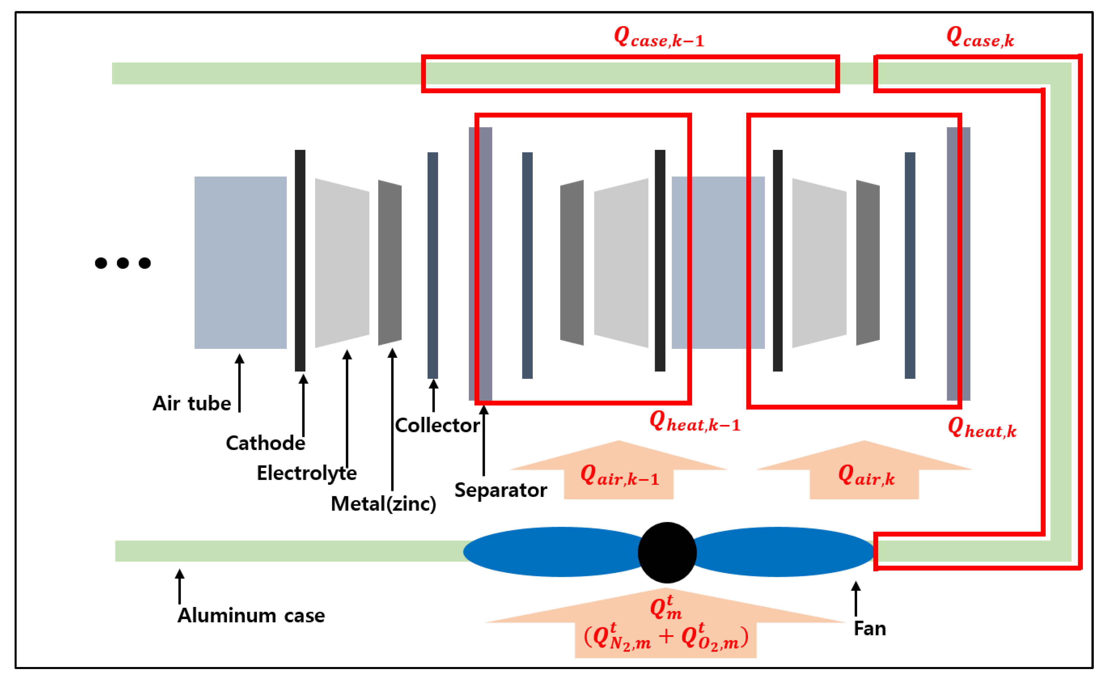
Figure 1. Schematic of stack structure and thermo-dynamical mechanism.
Energies 13 01611 g001
Figure 2. Overall view of the UPS model with the proposed receding horizon control (RHC).
Energies 13 01611 g002
Figure 3. Schematics of the prediction and solver window ( Δ W s o l v e r , k , Δ W p r e d i c t , k ) in RHC. These parameters are calculated as recursive structure of RHC. The optimal control values are calculated on Δ W s o l v e r , 1 , Δ W s o l v e r , 2 , …, Δ W s o l v e r , k within the iteration of Δ W p r e d i c t i o n , 1 .
Energies 13 01611 g003
Figure 4. Cell output voltage dependence on cell parameters: (a) current density and state of charge (SOC); (b) oxygen density and SOC; (c) temperature and SOC.
Energies 13 01611 g004
Figure 5. State variables on cell parameter by 1% and 100% of max fan flow control during operation: (a) current density; (b) oxygen concentration; (c) cell temperature.
Energies 13 01611 g005
Figure 6. Schematic of structure solving by approximate DP.
Energies 13 01611 g006
Figure 7. Cell temperature on electrical load cycle #2 by DP control.
Energies 13 01611 g007
Figure 8. State variables as simulation result in electrical load cycle #2 by different fan control: (a) cell temperature; (b) oxygen concentration.
Energies 13 01611 g008
Figure 9. Fan flow control for the different algorithms.
Energies 13 01611 g009
Figure 10. A comparison of increased zinc consumption by fan controls according to: (a) the electrical load cycles #1; (b) the electrical load cycles #2; (c) the electrical load cycles #3; (d) the electrical load cycles #4; (e) the electrical load cycles #5.
Energies 13 01611 g010
Table 1. Values of the parameters in the UPS module.
ParameterBasisValue
Stack area current   density   ~ 40   mA / cm 2 , load current 330 A 1.28   m 2
Max load powerload current 330 A, boost converter efficiency370 A
Module quantityload current 330 A, max current density0.16 m 2 , 8 modules
Stack voltage rangemin voltage 0.8 V, max voltage 1.1 V180–200 V
Cell stack quantityvoltage range, cell voltage170 cells
Metal weightsimulation result, demanded current 576 A200 g/cell
Metal thicknesscell surface area, metal weight0.15 mm/cell
Electrolyte thicknesssimulation result, other variables2 mm
Cathode thicknesssimulation result, other variables0.7 mm
Separator thicknesssimulation result, stack weight0.3 mm
Air tube thicknesscell array structure, airflow, air consumption16 mm
Module volumecell, airflow Length :   2   m ,   Volume :   1.44   m 3
Table 2. Required electrical load cycles representing different scenarios.
Max Power
64 kW
(Total Stack)
Run TimeGraphRun TimeGraph
7200 s Energies 13 01611 i00121,600 s Energies 13 01611 i002
14,400 s Energies 13 01611 i00311,800 s Energies 13 01611 i004