1. Introduction
One of the major concerns of development is the difficulties caused by the alarming increase in the energy crisis. Studies conducted by Sieminski et al. [
1], The International Energy Agency (IEA) [
2], and many more have indicated a 56% increase in the world’s energy demand by 2040. There has been a recast of the EU Energy Performance of Buildings Directive, which has directed that all new buildings must generate 20% of their energy requirements in a sustainable manner (EU [
3]). This directive has led to buildings adopting recent methodologies in active and passive design strategies to optimize overall efficiency by incorporating renewable energy mechanisms to reduce the cooling and heating loads (Stevanovi´c [
4]). Agathokleous and Kalogirou [
5] have shown that building-integrated photovoltaic (BIPV) systems present a promising solution for the generation of clean energy and reductions in heating and cooling loads posed by buildings through the exploitation of natural or forced ventilation, or by incorporating space heating or cooling through the flow of fluids.
Since the use of large-scale photovoltaic (PV) panels can be quite expensive, a cheaper alternative is the usage of optical concentrators that reflect sunlight onto one concentrated point to reduce the required cell area per unit output power (Meng et al. [
6]). In BIPV applications, studies conducted by Biyik et al. [
7] showed that concentrated photovoltaic systems also offer a greater advantage over conventional devices, as the electrical conversion efficiency is much higher and it provides a better approach for building facades. Such systems also aid in the generation of electrical and thermal energy, where the thermal energy can possibly be stored for various gray usage purposes, thus reducing the power required by water heating systems.
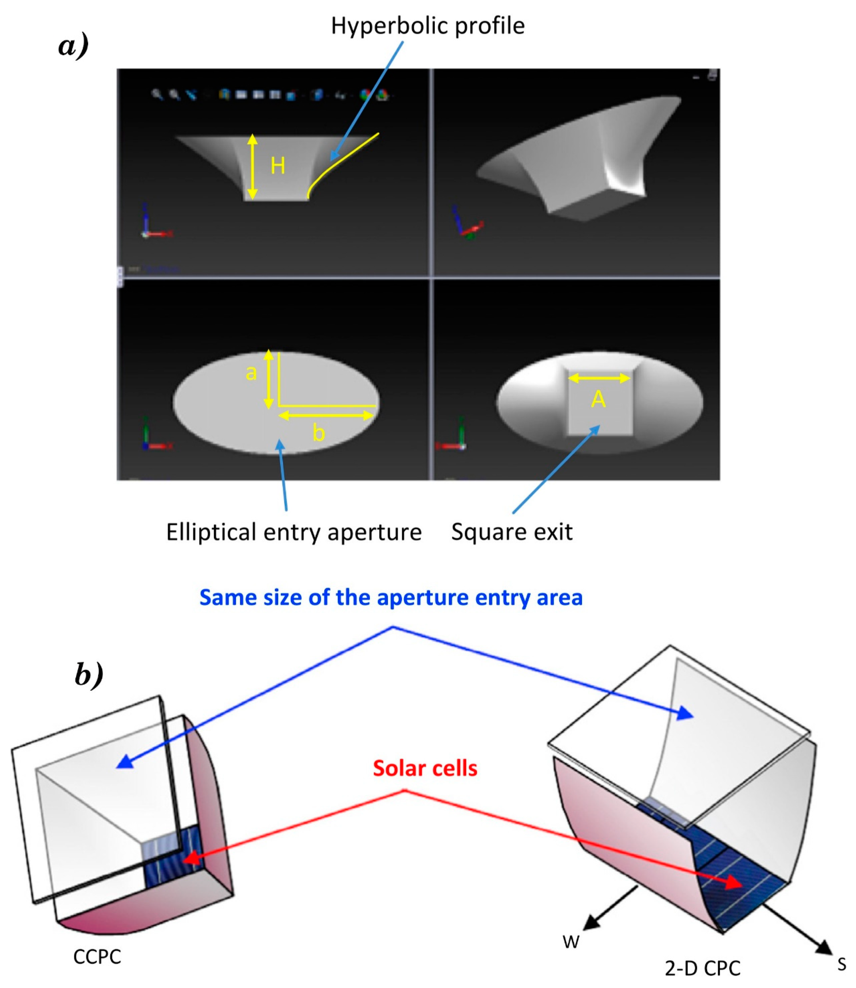
In order to address the development of a system capable of BIPV integration, compound parabolic concentration (CPC) devices, which are nonimaging solar concentrators with wide acceptance angles, have been widely studied. A typical CPC designed and tested by Sellami et al. [
8], called the Square Elliptical Hyperboloid (as shown in
Figure 1a), comprises two parabolic mirrors placed symmetrically so that the focal point from one mirror lies on the other. As reported by Sellami and Mallick [
9], although the typical 2D CPC offered a viable solution, further enhancement was required in the area of concentration and solar radiation collection. This led to the design of a 3D CPC module with a larger concentration ratio, in turn reducing the area per solar cell required. A 3D CPC is one of the most viable candidates in BIPV applications. However, due to the square and rectangular PV cells currently available on the market, its deployment has been challenging. To overcome this obstacle, a 3D cross-compound parabolic concentrator (CCPC) was developed by Mammo et al. [
10], in which two 2D CPC modules are intersected orthogonally to give a 3D CCPC module with square entry and exit apertures, as shown in
Figure 1b.
However, in such a system under illumination, PV cells undergo heavy losses due to the nonuniform pattern of illumination at the exit aperture (Chemisana [
11]). Sellami and Mallick [
9] developed a MATLAB code for a 3D ray trace, which showed that for a cross-compound concentrator with a concentration ratio of 3.6, about 50 times the energy of the incident sun rays from the optical flux distribution lies on the exit aperture. This concentrated energy in the form of heat leads to an increase in the temperature of the PV cells. An average PV cell, depending on the material properties of the cell, converts only about 4%–17% of the incoming irradiation into electricity. The remainder of this solar irradiation is converted to heat, which adds to the increase in temperature of the PV cell. This rise in cell temperature has a near linear output to the optical conversion efficiency of the PV cell in a negative gradient (Crook et al. [
12]). A constant rise in cell temperature typically leads to a drop in efficiency or permanent cell structure damage (Chow [
13]). From studies dating back to those conducted by Akbarzadeh and Wadowski [
14] and many more, it can be noted that collecting this thermal energy or alleviating the PV cell temperature is of utmost importance.
An effective cooling mechanism aids in the dissipation of the heat absorbed by the PV cells, maintaining the operating efficiency of PV cells under all conditions (Aldossary et al. [
15]). Passive cooling methods, making use of natural convection or phase-change materials such paraffin wax, are simple forms of technology which absorb the thermal energy and dissipate the heat from PV cells (Tan [
16]). However, passive cooling techniques are significantly affected by wind speed and ambient temperature. Studies conducted by Wei et al. [
17] showed that low wind speed and high ambient temperatures reduce the thermal absorption capability of Phase Change Materials (PCMs); thus, PCMs are not recommended for high-concentration and high-heat-intensity applications.
Active cooling mechanisms are more efficient methods, but they require pumps and reservoirs to supply the coolant to the module. Kerzmann and Schaefer [
18] extensively researched the use of an active cooling mechanism, where the flow rate of the coolant can be controlled to maximize the thermal absorption of the amount of heat generated by the module. This leads to an overall increase in the electrical conversion efficiency due to the decrease in cell temperature and an increase in the thermal efficiency of the system.
Various active cooling methods have been developed to aid in the cooling of photovoltaic applications, such as the mathematical model developed by Moharram et al. [
19] to calculate the optimal time to begin PV cell cooling by water spraying to maintain the optimal operating temperature. Although this model aids in the cooling of the photovoltaic system, it does not aid in the absorption of the thermal energy which is generated and, moreover, this is a purely theoretical model with no experimental validation. Al-Amri and Mallick [
20] have also developed a mathematical model to alleviate the operating temperature of PV cells by air active cooling and surface radiation. This research shows promising results, as the operating temperature of the PV cells was kept in the optimal range while allowing an increased concentration of over 50%. However, like previous studies, although there was an active cooling mechanism, no study was conducted to harness the thermal energy generated.
An active cooling mechanism can not only reduce the PV cell temperature, but it can also absorb the thermal energy generated within the module. Within the active cooling mechanism, there is an increase in the fluid outlet temperature, which can be used to lower the heating loads pertaining to the system to which the module is applied. Teo et al. [
21] developed an experiment to test the efficiency of air active cooling PV panels by blowing cold air through the back of a PV panel. They were able to increase the operating efficiency of the PV cells, maintaining a constant temperature of 38 °C and 13% PV cell efficiency at a mass flow rate of 0.04 kg/s. The research also indicates a rise in the outlet air temperature, which, when stored, can be used for the purpose of space heating.
The usage of air to cool a photovoltaic system is not the most efficient cooling method, as it is difficult to store the thermal energy from the outlet. Hence, the usage of a fluid based coolant was suggested by Ghani et al. [
22] due to its increased thermal absorption capability, as well as its ease of storage and transport, since this cooling mechanism is for BIPV applications where water as a coolant is readily available.
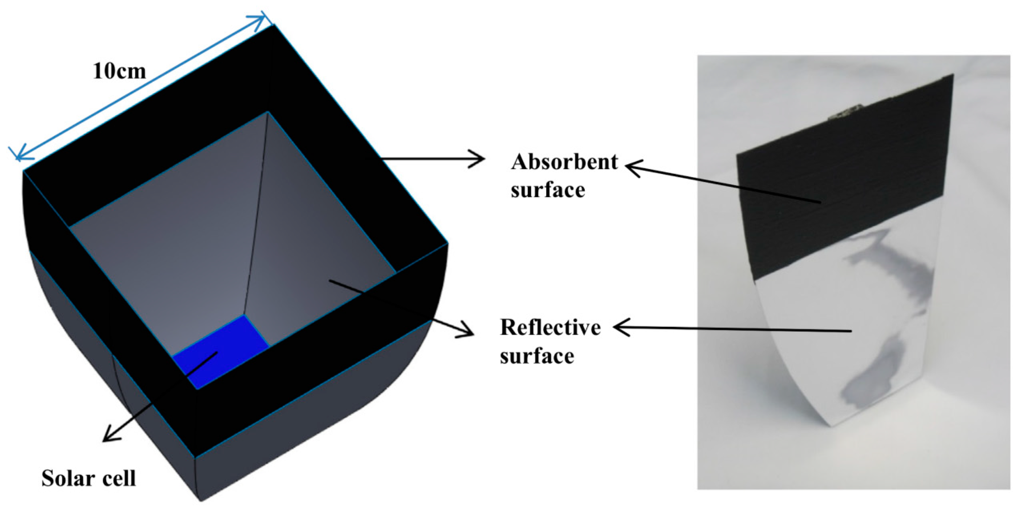
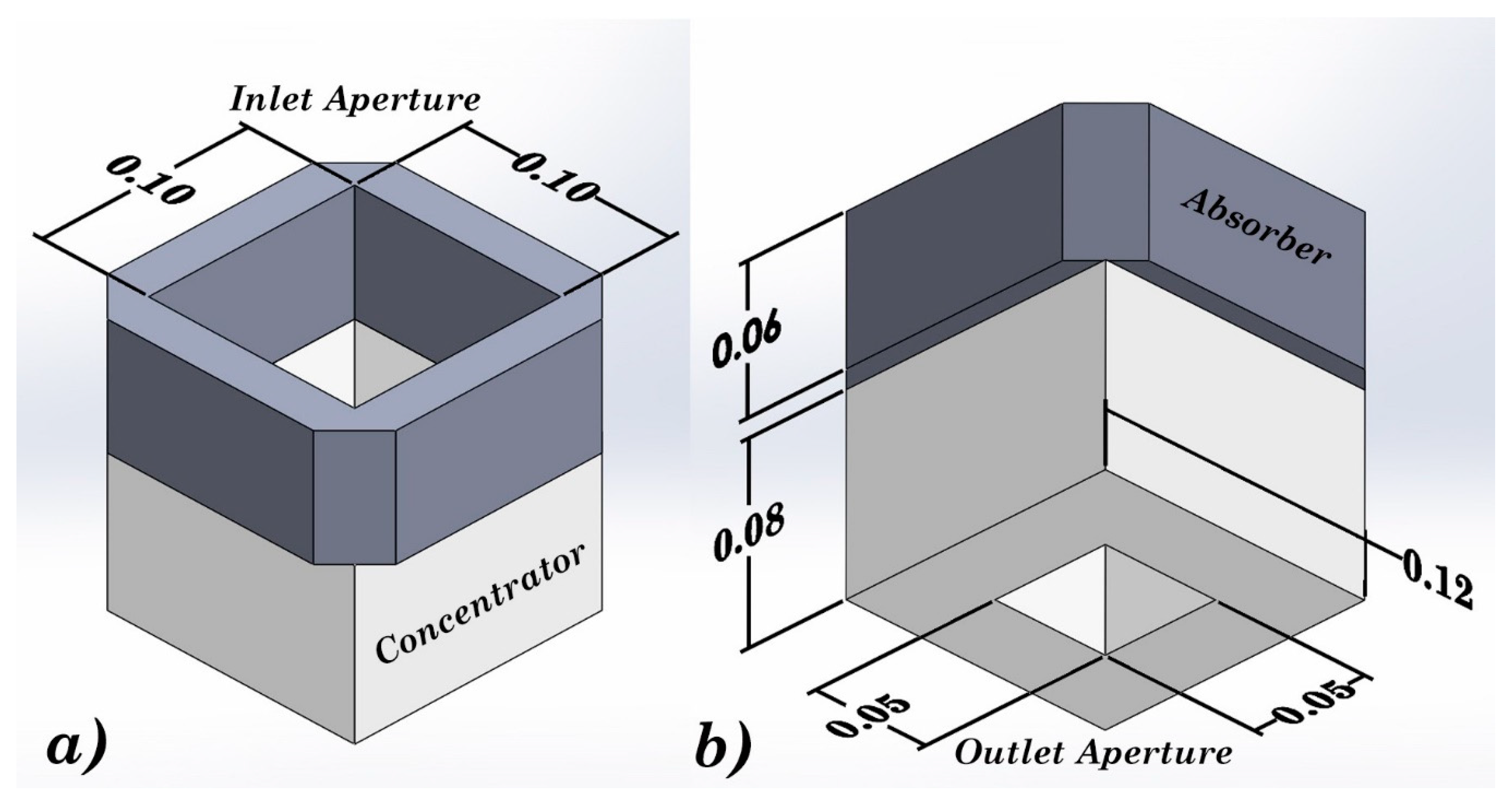
In this study, we experimentally investigated a new-generation absorptive/reflective cross-compound parabolic concentrator (AR-CCPC) module designed by Meng et al. [
23], as shown in
Figure 2.
The novelty of the AR-CCPC module is that it comprises an absorptive and reflective optical region, as depicted in
Figure 2a,b, for combined heat and electricity generation actively cooled by water passing through the module. The absorber surface aids in collecting the thermal energy generated by the incident irradiation on the module surface, whereas the reflector region aids in the reflecting of solar irradiation incident on the module onto the PV cells through an acceptance angle of −30° to 30°. The module was designed to have a concentration ratio of 3.6×/4×, which is nothing but the ratio of the area of the inlet and outlet aperture.
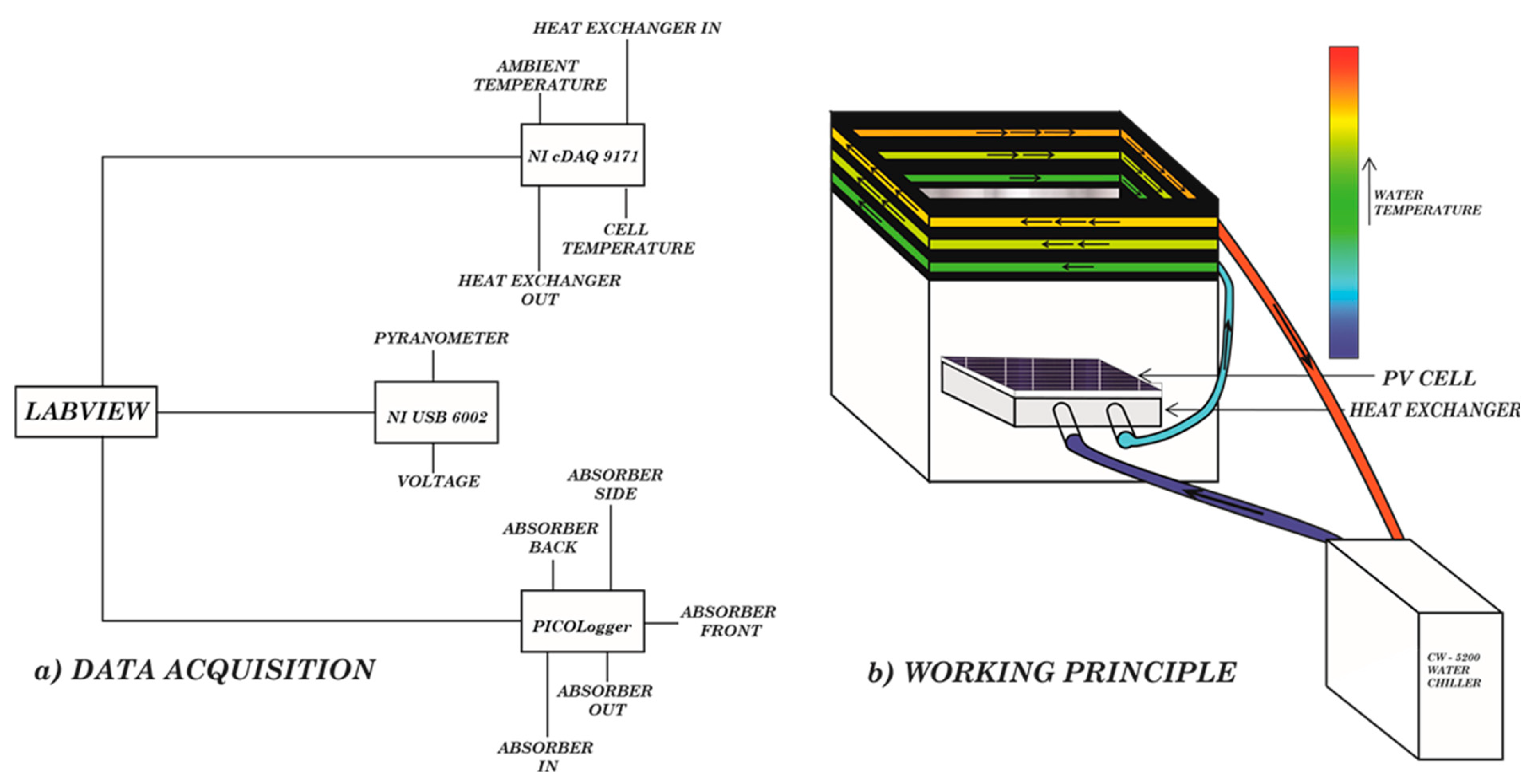
The experiment was carried out at the Heriot Watt University campus in Dubai, and the analyses were conducted under the effect of various levels of irradiation received throughout the day. This study aimed to experimentally investigate the characteristics of this novel system and evaluate the use of a heat exchanger and active cooling mechanism for cooling PV cells and absorbing the thermal energy generated. This work also addressed the effect of the angle of incidence on the characteristics of the concentrator.
3. Results and Discussions
The novelty in experimentally investigating the characteristics of the AR-CCPC module was the experimental methodology, which was followed to achieve the desired results, as explained below. Numerous tests were conducted under the influence of varying solar irradiation and ambient temperatures. First, the tests were conducted without the active cooling mechanism to evaluate the extent of cooling required in such a system, after which the active cooling system was integrated and the module was tested under cooled conditions. As the rate of thermal energy recovered and the effect of cooling are highly dependent on the mass flow rate of the coolant through the rig, the effects of cooling and the thermal absorption were investigated under varying mass flow rates. The effect of cooling and thermal absorption are inversely proportional to each other, as shown in studies conducted by Sabharwall et al. [
26]; hence, the optimal flow rate is that which gives an ideal balance between the two factors.
3.1. AR-CCPC Performance without Cooling
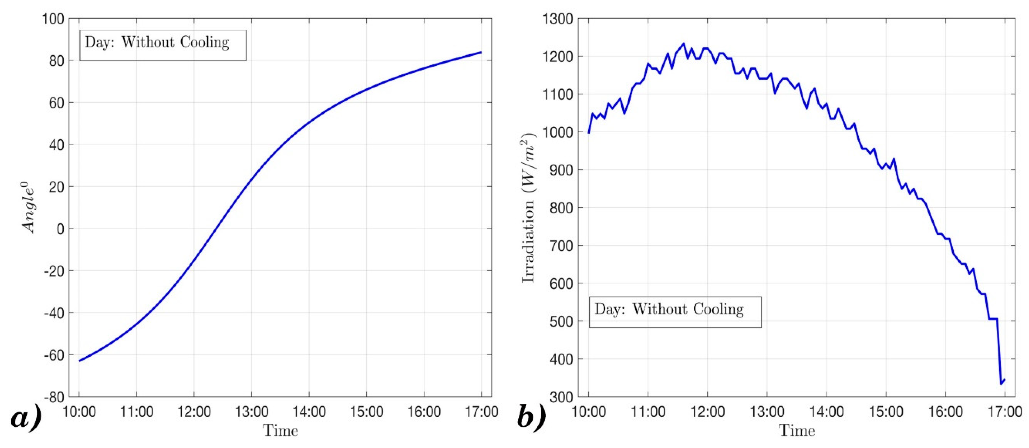
To understand the basic characteristics of the AR-CCPC module, the experiment was conducted without an active cooling mechanism under the test conditions as depicted in
Figure 7.
The test was conducted for a period of 7 h from 10 a.m. to 5 p.m.
Figure 7a shows the variation in the angle of incidence, wherein the 0° of incidence was when the sun was directly overhead of the module.
Figure 7b depicts the variation of the solar irradiation incident on the rig throughout the testing period. The solar irradiation peaked at the solar noon when the angle of incidence was 0°. On the day of testing, the maximum solar radiation incident on the module was 1260 W/m
2.
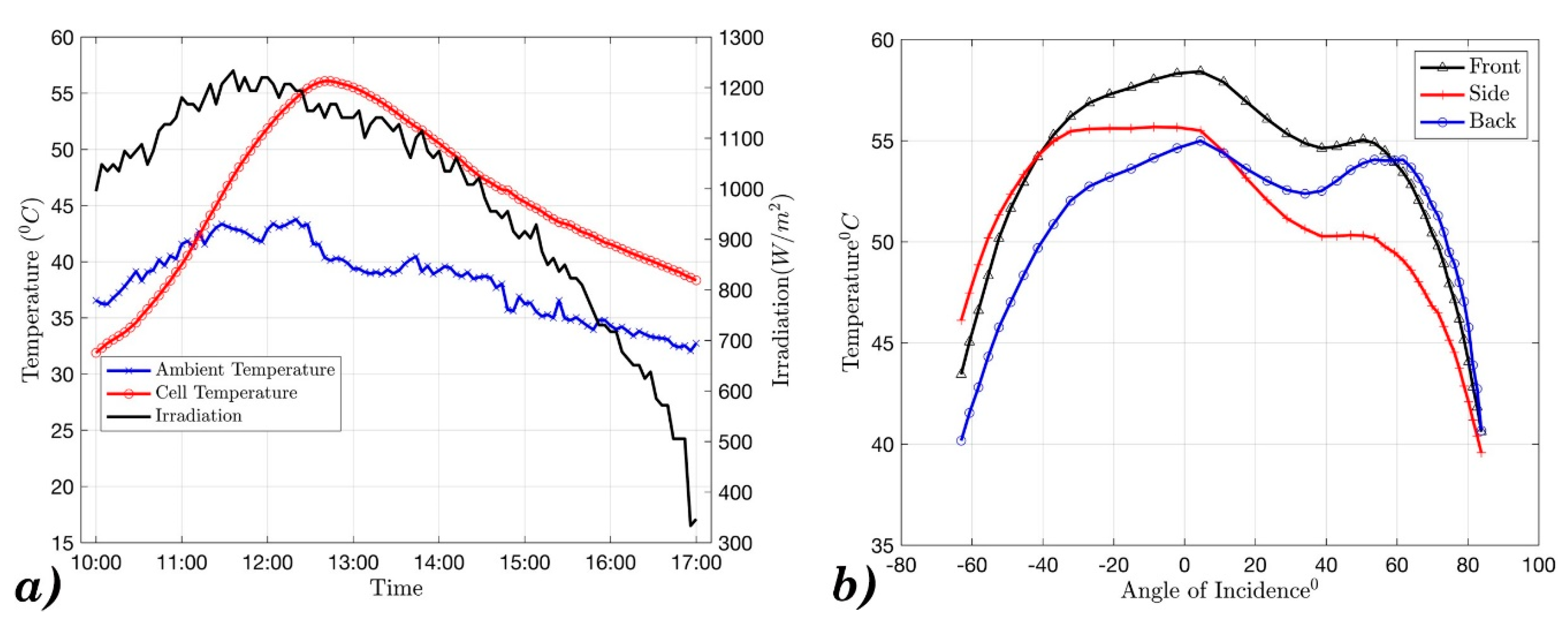
Figure 8a shows that throughout the 7 h testing period, there was a gradual rise in the temperature of the PV cell, which ultimately reached a maximum value of 57 °C right after solar noon, when the angle of incidence had just crossed 0°. From the literature, it is evident that an increase in cell temperature leads to a drop in efficiency and, hence, an active cooling mechanism must be installed to cool the cell.
Figure 8b shows the variation in the temperatures of the absorber surface. The module was oriented such that the front surface was facing the sun through the period of −80° to 0° angle of incidence. At this point, the front face of the absorber gained more heat compared with the side and the back surface.
These results extensively address the need for an active cooling mechanism, as such a mechanism can aid in the cooling of the PV cell, ultimately maintaining the PV cell at an ideal electrical conversion efficiency and absorption of the heat collected by the absorber surfaces in the form of thermal energy for later usage.
3.2. AR-CCPC Performance with Cooling
As the AR-CCPC module is a device proposed for BIPV application, the coolant used was water, which was supplied to the rig at a constant temperature of 18 °C. As the mass flow rate of the water supplied to the module affects the cell temperature and the thermal efficiency of the system in an inversely proportional manner, the effect of four different mass flow rates was tested.
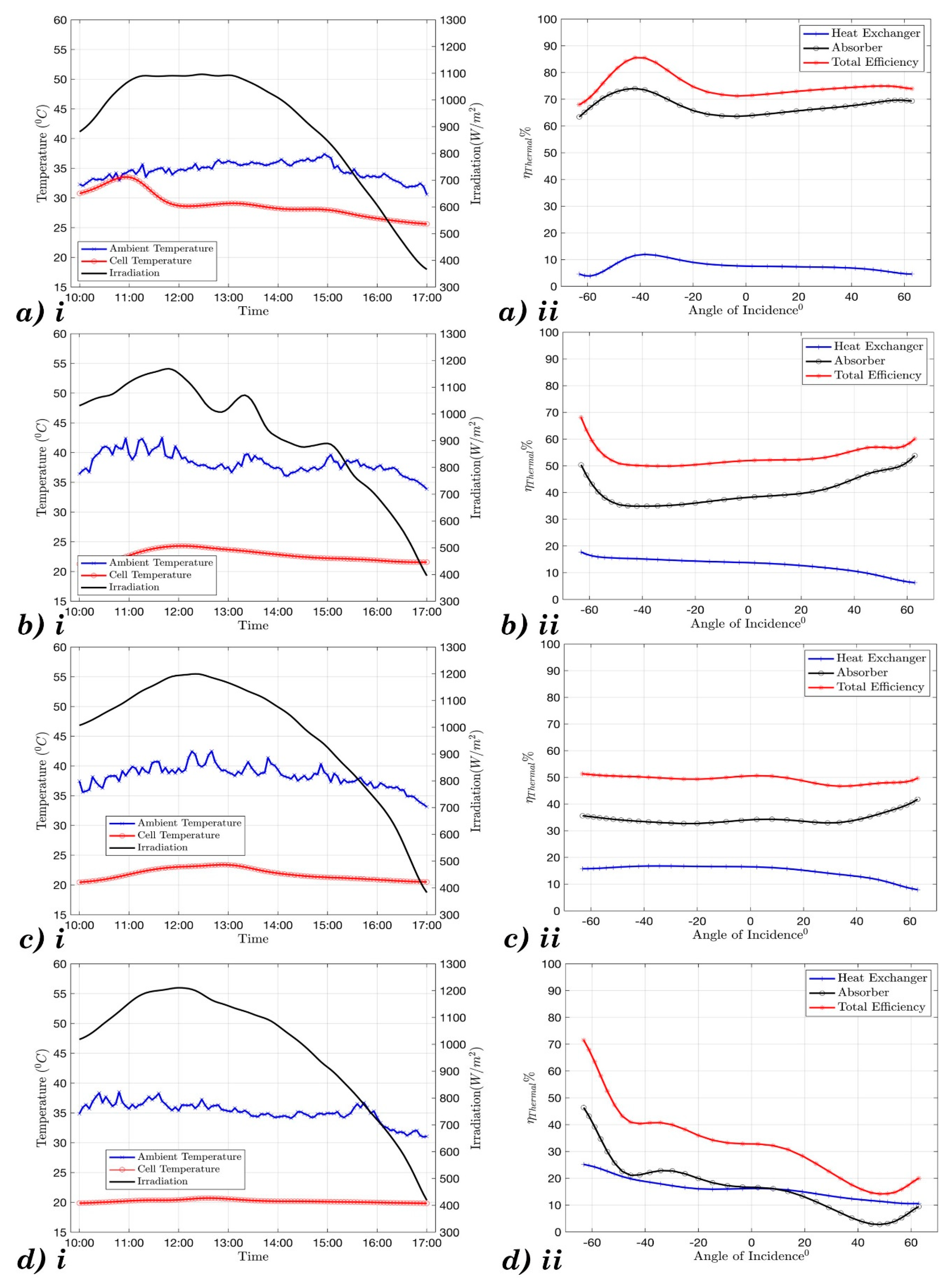
Figure 9 depicts the variation in the cell temperature and the thermal efficiency of the module.
From a quick look at
Figure 9, it can be noticed that the active cooling mechanism reduced the temperature of the PV cell drastically compared with the temperature without cooling. The thermal efficiency of the system can be calculated by the general equation as suggested by Duffie and Beckman [
27]:
where
where the symbol
ṁ is the mass flow rate in kg/s,
cp is the specific heat capacity of the water in J/kg.K, and ∆T is the temperature difference of the coolant entering and leaving each component.
which leads to the thermal efficiency equation, which is defined as the ratio of the total amount of thermal energy collected over the input energy, which is equal to the radiation at the entry aperture of the AR-CCPC:
As the module contained an absorber surface and heat exchanger, absorbing heat led to two thermal efficiencies, namely, the heat exchanger efficiency and the absorber efficiency.
Upon analyzing the effect of various flow rates,
Figure 9c shows that flow rate of 1 L/m is the optimal volume flow rate for this experiment due to the balance between maintaining low cell temperature and high thermal efficiency. This flow rate ensures that the PV cell is working at its ideal conditions at a cell efficiency of 15.16%. This flow rate also ensures a reasonable thermal efficiency which adds to the overall system efficiency.
3.3. Power Generated by the AR-CCPC Component
Power is the multiplication of the current and voltage generated by the PV cell, when variable resistance is present in the system. Due to experimental limitations, the current produced by the PV cell could not be measured. Hence, the power of the PV cell had to be approximated through detailed calculations. The power generated by the PV cell is dependent on two factors: the temperature of the PV cell and the acceptance angle of the module. Power is directly proportional to the voltage produced; hence, a higher voltage ultimately leads to higher power generation.
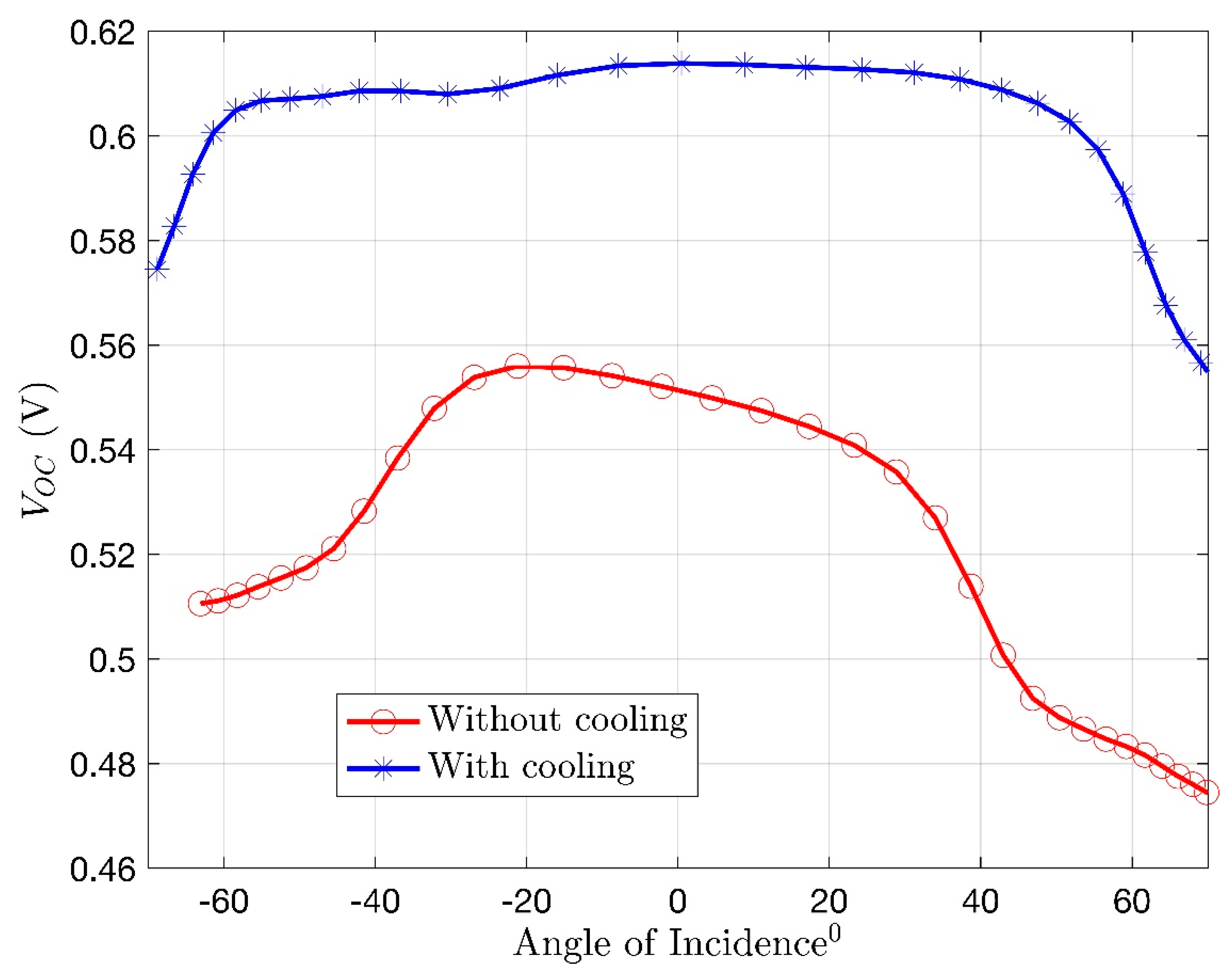
Figure 10 depicts the open circuit voltage produced by the PV cell when an active cooling mechanism is or is not employed.
Figure 10 depicts the rise in the open circuit voltage produced by the PV cell under the influence of cooling. A significant 9.2% increase in the voltage output was achieved with the help of active cooling, wherein the cell temperature was maintained at its optimal temperature for maximum electrical conversion efficiency.
It can be noted from the trend in the graph that as the angle of incidence approached the acceptance angle, the voltage output of the PV cell increased, where it reached the maximum value at a 0° angle of incidence, after which it began to decrease till the end of the acceptance angle. Before and after an angle of incidence of −30° to 30°, respectively, the voltage produced by the cell was purely due to the diffused radiation and some radiation which was reflected off the absorber surface.
The power generated by the PV cell in an AR-CCPC module also depends on the optical efficiency of the rig. The optical efficiency is the ratio between the irradiation received on the solar cell upon the irradiation received at the inlet aperture. The optical efficiency of the AR-CCPC lies between the acceptance angle with which the module is designed, which is an angle of incidence of −30° to 30° (Sellami and Mallick [
9]). Solar radiation incident on the rig at an angle of incidence higher or lower than the acceptance angle does not reach the PV cell and, hence, the power generated is negligible. The optical efficiency of the module is highest at a 0° angle of incidence, leading to the maximum power output.
The optical efficiency is given by the formula developed Cox III and Raghuraman [
28]:
The irradiation received by the PV cell can be obtained by,
As the module is actively cooled, to maintain the optimal cell temperature for the highest electrical conversion efficiency of 15.16%, the power generated by the PV cell can be calculated as
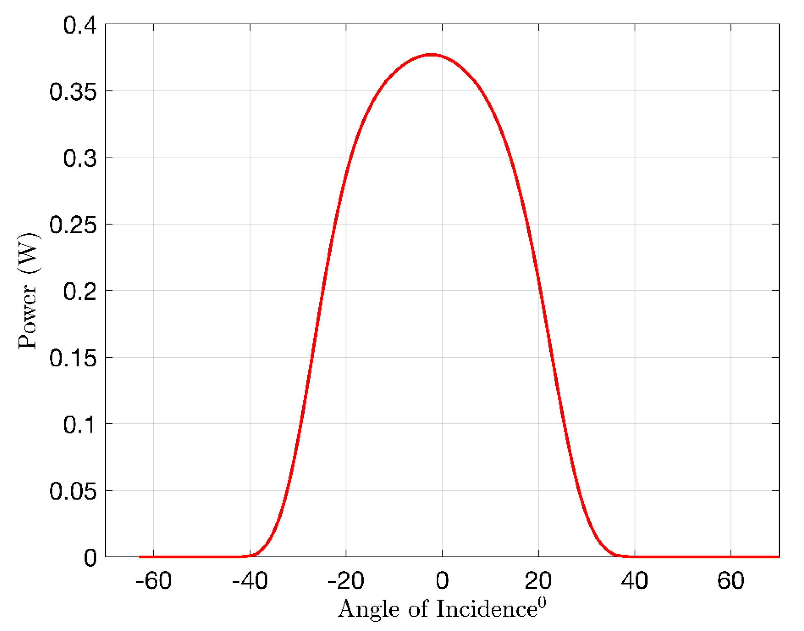
The variation of power obtained from Equation (8) in terms of magnitude with respect to the angle of incidence is shown in
Figure 11. It shows the variation of the power generated by the module with respect to the angle of incidence. As seen in the graph, theoretically, there is no power generated by the cell before and after an angle of incidence of −30° and 30°.
From the equation relating the power of the PV cell with the incident irradiation on the PV cell, we can see that the power generated also depends on the incident irradiation in a directly proportional manner.
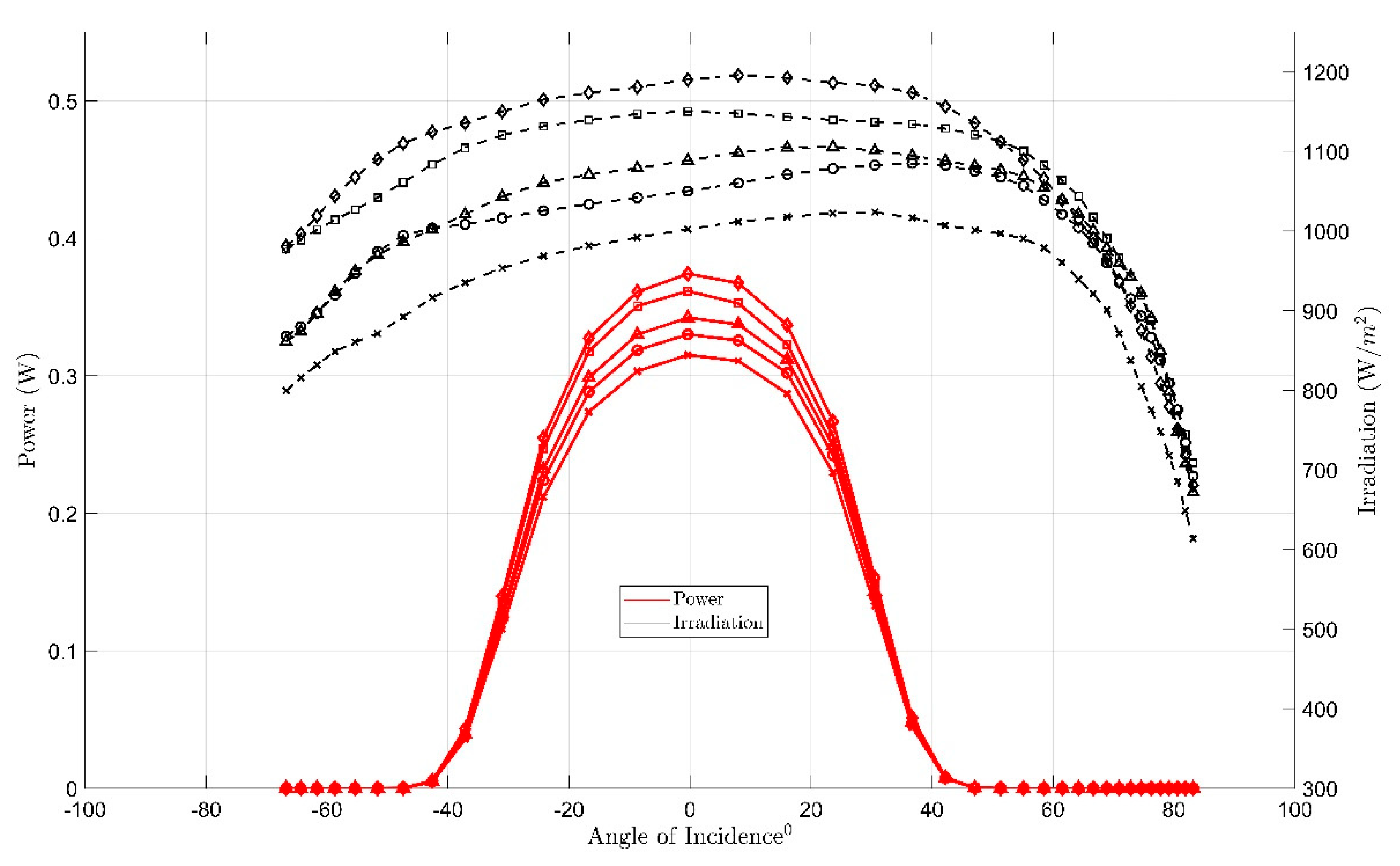
Figure 12 depicts the irradiation experimentally tested over a period of 5 days, and the electrical power generation was calculated using Equations (5)–(8) and the optical efficiency of the CCPC.
As shown in
Figure 12, a direct relation to the effect of irradiation on the power generated by the module was established. The least power was generated on a day of lower irradiation due to scattered clouds of dust in the atmosphere. The maximum power output generated by the module was obtained on the day of maximum irradiation due to clear skies. From
Figure 12, it can be noted that the irradiation and the power peaked at solar noon, when the angle of incidence was 0° or the sun was directly overhead of the module. The irradiation received on the module followed the trend of the acceptance angle. Thereby, the maximum irradiation received on the rig was within the acceptance angle of the module.
To achieve a maximum power output, it is essential that the module is placed in a position that receives the highest amount of solar radiation and the module entry aperture must not be blocked by external factors during the period wherein the angle of incidence of the irradiation on the entry aperture lies within the acceptance angle of the module.
3.4. Overall System Efficiency
The AR-CCPC module was designed to generate electrical as well thermal energy for various applications. The overall system efficiency of the module comes from the summation of the thermal energy generated by the absorber and heat exchanger and the electrical energy generated by the module with respect to the angle of incidence and cell temperature.
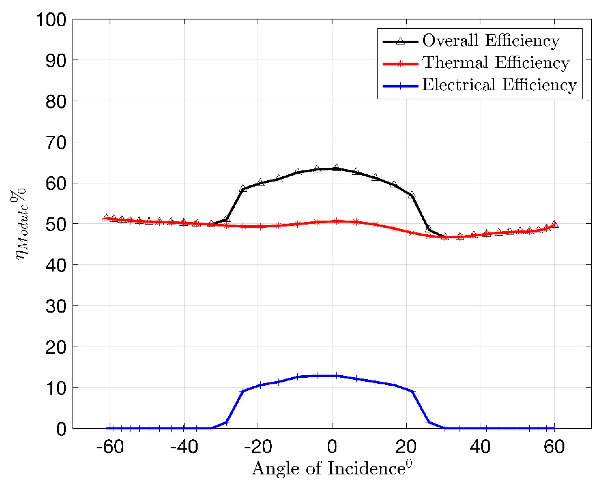
Figure 13 depicts the overall efficiency of the AR-CCPC module that was experimentally tested.
Figure 13 shows the overall efficiency of the module. The electrical efficiency of the module was assumed to reach approximately 15%, which is the maximum electrical conversion efficiency under standard test conditions and an operating temperature of 20 °C. The heat exchanger integrated beneath the PV cell that comprised the active cooling mechanism aided in maintaining the optimum cell temperature for maximum electrical conversion efficiency. This controlled cell temperature and the amount of irradiation incident on the cell, depending on the angle of incidence, contributing to the electrical efficiency of the module. The active cooling system also aided in the absorption of the thermal energy generated within the rig. The coolant passing through the module absorbed the heat collected by the PV cell and the absorber surfaces. The thermal efficiency shown in
Figure 13 constituted the thermal efficiency due to the heat collected through the heat exchanger and the absorber surface. There is a slight peak in the graph between −20° and 20° angle of incidence, which is due to the increase in surface temperatures of the module when the angle of incidence lay within the acceptance angle of the module. The system under investigation has shown to have an overall efficiency of about 65%. However, this efficiency is lower than the designed overall efficiency due to errors in manufacture, dust accumulation on the entry aperture, and the heat loss due to the surroundings because of improper insulation of the water channels and piping, which were exposed to ambient conditions.
4. Conclusions
A novel AR-CCPC module was experimentally investigated to understand the characteristic properties of the module. The module consisted of an absorber region used to absorb the thermal energy from the solar radiation and a reflective region used to reflect the solar irradiance onto a PV cell. The module was designed to have an acceptance angle of −30° to 30°. Under the influence of solar irradiation and high ambient temperatures, the module rapidly gained heat. The absorber surface showed a rise in temperature with the variation in the angle of incidence of the sun through a fixed period of testing. As the PV cell was placed within a concentrator, the PV cell rapidly heated up, leading to a decrease in power generation. An active cooling mechanism was employed in the system through the integration of a heat exchanger beneath the PV cell to absorb the heat collected by the PV cell and through the installations of water channels in the absorber region to absorb the heat from the surface. The optimal volume flow rate of the coolant to pass through the module was selected on the basis of the lowest cell temperature and highest thermal efficiency. A flow rate of 1 L/m was shown to moderate a fair balance between the criteria. The voltage generated by the module was highly dependent on the angle of incidence, with the highest voltage being generated within an angle of incidence of −35° to 35°. The power being directly proportional to the voltage of the PV cell in turn peaked during the same angle of incidence, with the maximum power being generated at a 0° angle of incidence. The system was found to have an overall efficiency of 63%, combining the thermal efficiency of the heat exchanger and the absorber surface and the electrical efficiency of the PV cell.
The module efficiency can be further improved by further analyzing the flow pattern of the coolant around the absorber surface so as to develop the ideal flow configuration and optimal volume flow rate with which the coolant must pass through the module. The thermal efficiency can be further optimized by selecting a heat exchanger with a larger heat transfer area, so as to further cool the PV cell and extract more heat from its surface. The electrical efficiency of the module can be increased by looking into alternative solar cell options that inhibit a higher electrical conversion efficiency.
This model, once fully optimized, can be a proposed addition to dedicated water heating systems installed atop buildings to provide warm water for gray usage throughout the building. Media [
29] has accounted for an increasing demand in low-temperature warm waters for HVAC systems for the purpose of space heating. The electrical power could potentially be used to pump the water from a reservoir to the module and from the module into the water heater reservoir. Such an application can provide buildings with renewable energy sources for maintenance.


