Article

Semi-Analytical Modeling and Analysis of Halbach Array

School of Electrical and Electronics Engineering, Chung-Ang University, Seoul 06974, Korea
*
Author to whom correspondence should be addressed.
Energies 2020, 13(5), 1252; https://doi.org/10.3390/en13051252
Submission received: 5 February 2020 / Revised: 2 March 2020 / Accepted: 5 March 2020 / Published: 8 March 2020
(This article belongs to the Special Issue Design and Analysis of Electric Machines)

Abstract

:
Analysis of Halbach array placed in open space by using finite element method involves substantial consumption of memory, time, and cost. To address this problem, development of a mathematical modeling and analytic analysis method for Halbach array can be a solution, but research on this topic is currently insufficient. Therefore, a novel mathematical modeling and analytic analysis method for Halbach array in open space is proposed in this study, which is termed as the Ampere model and the Biot–Savart law (AB method). The proposed AB method can analyze the Halbach array rapidly and accurately with minimal consumption of memory. The usefulness of the AB method in terms of accuracy and memory and time consumption is verified by comparing the AB method with finite element method in this paper.

1. Introduction

Halbach array (HA) was proposed by K. Halbach to maximize the efficiency in a given volume of a permanent magnet (PM) via the combination of PMs, which are magnetized in diverse directions [1]. By combining PMs appropriately, an effective magnetic flux path can be obtained without using magnetic cores. The combination of the PMs is termed as HA.
By the appropriate arrangement of PMs, which are magnetized in different directions, it is possible to divert the magnetic flux in unnecessary areas to the required area. This renders enhancement of the magnetic flux in the required area and reduction of the same in the unnecessary area. Hence, maximization of the efficiency of a magnetic field system is possible with the usage of restricted volume of PMs [2,3,4,5,6,7,8].
A high permeability core material is commonly used to obtain an effective magnetic flux path. However, core losses, such as hysteresis loss and eddy current loss occur in the core and lower the efficiency of the magnetic field system. On the other hand, when the HA is used for the magnetic system, an effective magnetic flux path can be obtained without using the core, and the efficiency of the magnetic field system can be increased.
Nevertheless, the cost of an electric machine could be increased when HA is used due to the manufacturing difficulties of HA arising from factors such as the bonding difficulties of PMs, which are magnetized in different directions, etc. However, as there are many merits of HA, it is widely used for diverse kinds of electric machines, such as, motor [9,10,11,12,13,14,15], maglev [16,17], eddy current brake [18,19,20,21,22], actuator [23,24], magnetic bearing [25,26,27], energy harvester [28,29,30,31], etc.
Most studies on the analysis of HA have been focused on the case where the HA is placed with high permeability cores in a small air gap [9,10,11,12,13,14,15,16,17,18,19,20,21,22,23,24,25,26,27,28,29]. Moreover, HA was modelled and analyzed through the methods of the magnetic circuit method [9], image method [10,12], Fourier series [15], and Layer method [18,24]. The above methods are not applicable if the device contains no ferromagnetic core and has wide airgap. However, in some cases, the HA can be placed in open space and most of the magnetic flux can pass through a long distance in air such as when it is used in energy harvester around the transmission line [30,31].
The finite element method (FEM) can deal with the problem, but it needs much time and memory to analyze. These days, the use of more efficient computational methods is of extreme importance to reduce energy consumption in computing centers [32], and FEM cannot satisfy this issue.
To address this problem, a novel and useful mathematical modeling and analytic analysis method is proposed in this research for HA placed in open space. Specifically, the mathematical model is derived for PM and HA by considering the Ampere model, Gilbert model, and Ampere’s circuital law. The governing equations and analytical method for the analysis of HA are derived in this paper by applying the Ampere model and the Biot–Savart law. Hence, the proposed method in this study is termed as Ampere model and the Biot–Savart law (AB) method.
The usefulness of the proposed mathematical model and analysis method in terms of accuracy and time consumption is validated by comparison with the finite element method (FEM).

2. Structure and Working Principle of HA

There are diverse kinds of arrangements for HA depending on its applications. The arrangement of the HA used in this study is a basic one that is widely used, as shown in Figure 1c, which corresponds to the case that uses the magnetic flux flowing in the −z direction area.
The model of Figure 1c is the combination of Figure 1a,b to maximize and utilize the magnetic flux in the −z direction. Figure 1a shows a combination of PM elements magnetized in +z and −z directions. Figure 1b shows the arrangement of PM elements magnetized in +x and −x directions.
By combining the PM elements demonstrated in Figure 1a,b, the magnetic fluxes generated by the models in Figure 1a,b are superimposed, as illustrated in Figure 1c. Hence, the magnetic flux in the +z direction is canceled out and the flux in the −z direction is augmented. In other words, by using the arrangement of HA shown in Figure 1c, it is possible to add the magnetic flux flowing in the +z direction, which is not utilized, to the −z direction where the magnetic flux is used.
A given PM has a limited amount of total magnetic flux. Therefore, it is helpful to use the HA structure to maximize the magnetic flux in the utilized area within a given PM volume. In other words, the cost and volume of PM can be minimized by applying the HA.

3. The Proposed AB Method for PM

This section may be divided by subheadings. It should provide a concise and precise description of the experimental results, their interpretation, as well as the experimental conclusions that can be drawn.

3.1. Mathematical Model of PM

There are two mathematical models of PM for the analysis of its magnetic characteristics: Ampere model and Gilbert model.
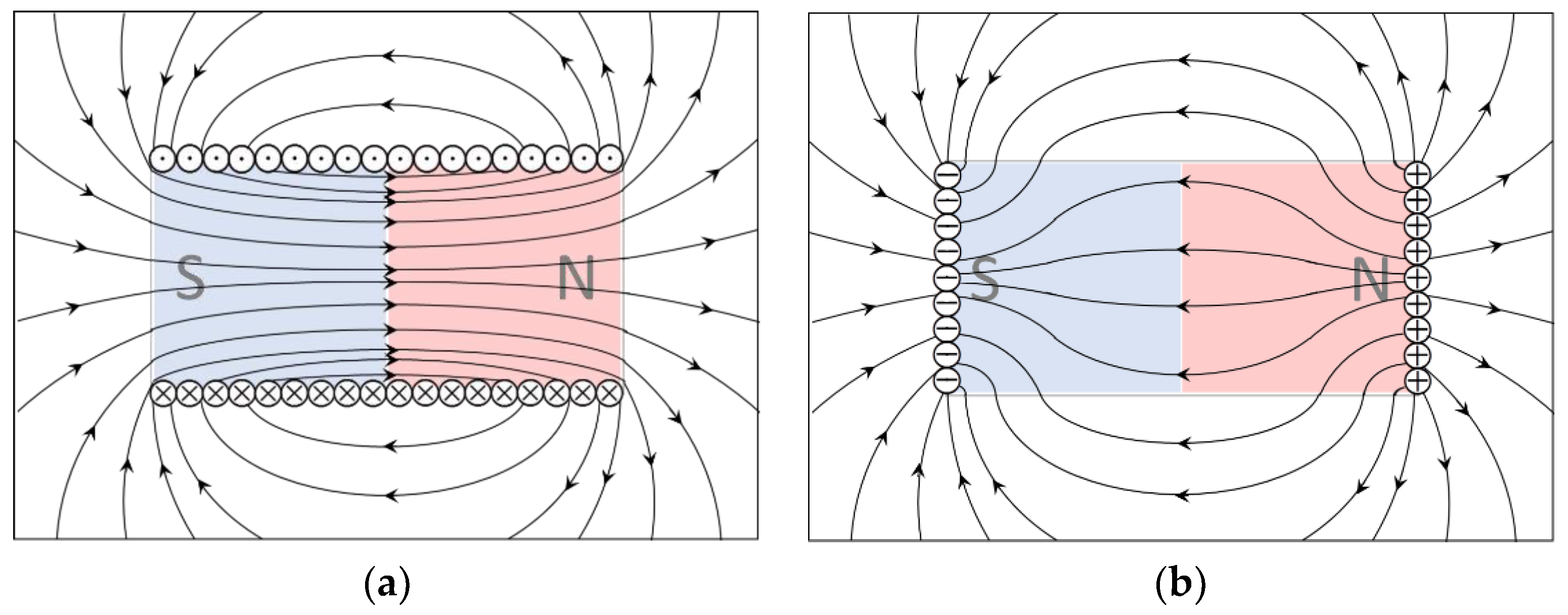
As shown in Figure 2a, in the Ampere model, the PM is assumed as an equivalent Amperian current or bound current flowing on the surface of PM, and the magnetic flux is generated by the Amperian current.
As shown in Figure 2b, the Gilbert model assumes the PM as an equivalent magnetic charge. The polarity of the magnetic charge in the Gilbert model corresponds to the North and South pole of PM. The magnetic charge is defined as a unipolar charge, not a dipole, and is distributed in the area of the corresponding polarity in the PM. Therefore, in the Gilbert model, the magnetic field generated by the PM can be calculated as done in the case of calculating the electric field of electric charge by Coulomb’s law.
The Gilbert model is reasonable for the demonstration of the magnetic field outside the PM. However, the magnetic field inside the PM of the Gilbert model is quite different from the actual magnetic field, as shown in Figure 2b.
Therefore, the Ampere model can be useful for the analysis and design of PM machine which uses magnetic field near PM. In this study, the Ampere model is used for the derivation of the analytic method for the analysis of PM.

3.2. Application of Amperian Current into PM

The Ampere model assumes the PM as an equivalent current loop. Therefore, in this paper, an analytic method for the analysis of the magnetic field generated by PM is proposed via the assumption of the equivalent current loop of PM and by using the Biot–Savart law.
The sum of the Amperian currents flowing through the surface of the PM can be determined using Ampere’s circuital law. In other words, the total current Im, which is the summation of each Amperian current i of PM in the Ampere model, can be obtained by integrating the magnetic field intensity H over the length l as shown in Equation (1).
I m = i = H d l
The total current Im can be calculated using an equivalent magnetic circuit model and by using the material property B-H curve of the PM.
Through the B-H curve of magnetic material, the linear relationship between the residual magnetic flux density Br and the coercive force Hc can be found. Moreover, by modeling the permanent magnet in the form of a Norton equivalent circuit, the magnetomotive force of the permanent magnet can be calculated [33].
Therefore, the total current Im can be obtained by multiplying the coercive force Hc by the length L in the magnetization direction of the PM.
I m = H c L

3.3. Amperian Current Distribution Modelling in HA

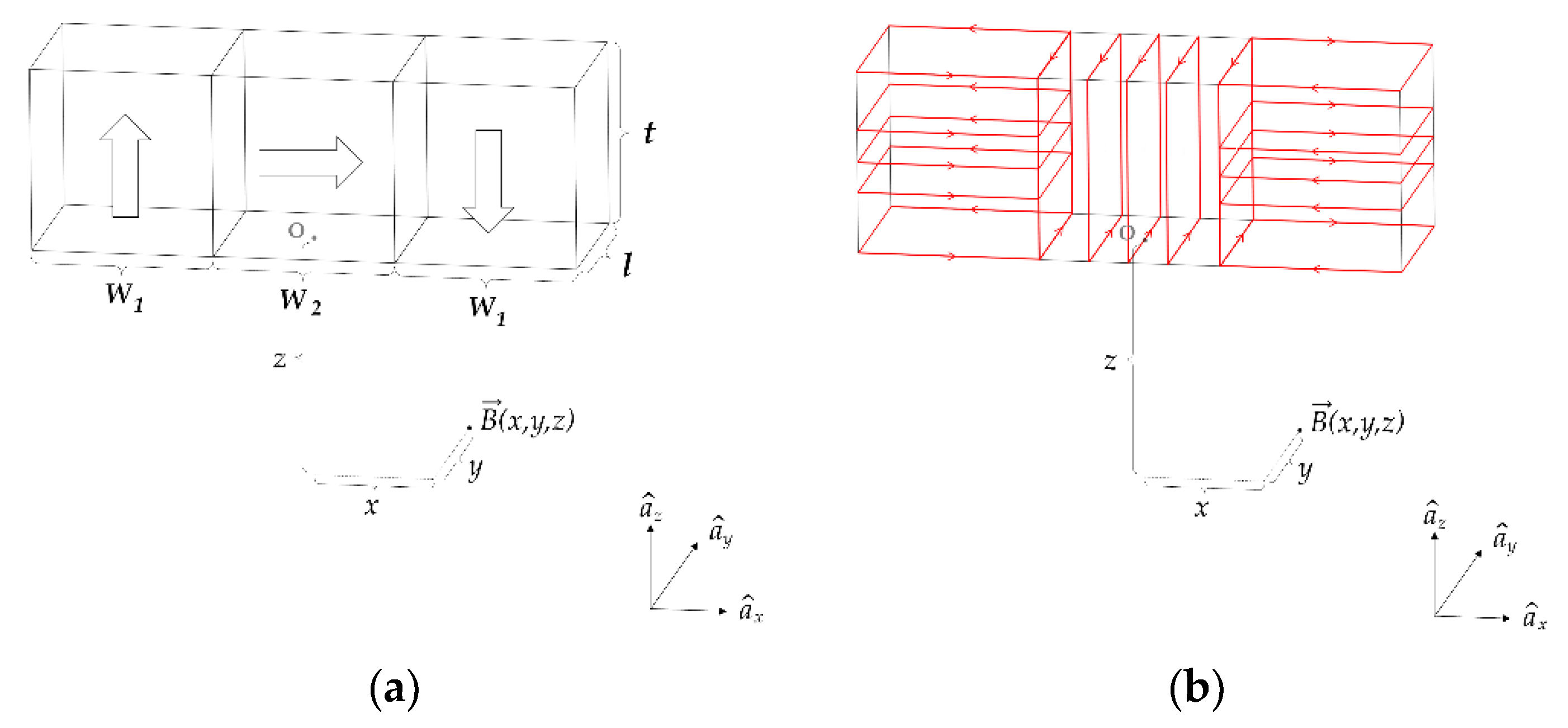
In this study, the most common and widely used arrangement of HA shown in Figure 1c is considered. For the verification of the proposed analysis method, the model of Figure 3a, which utilizes the minimum number of PMs (three PMs) for maximizing the −z direction magnetic flux, is used.
As shown in Figure 3b, the HA demonstrated in Figure 3a is converted into the Ampere model via current distribution flowing at a constant interval on the PM surface.
O means the origin with coordinates (0,0,0) in Cartesian coordinate system.
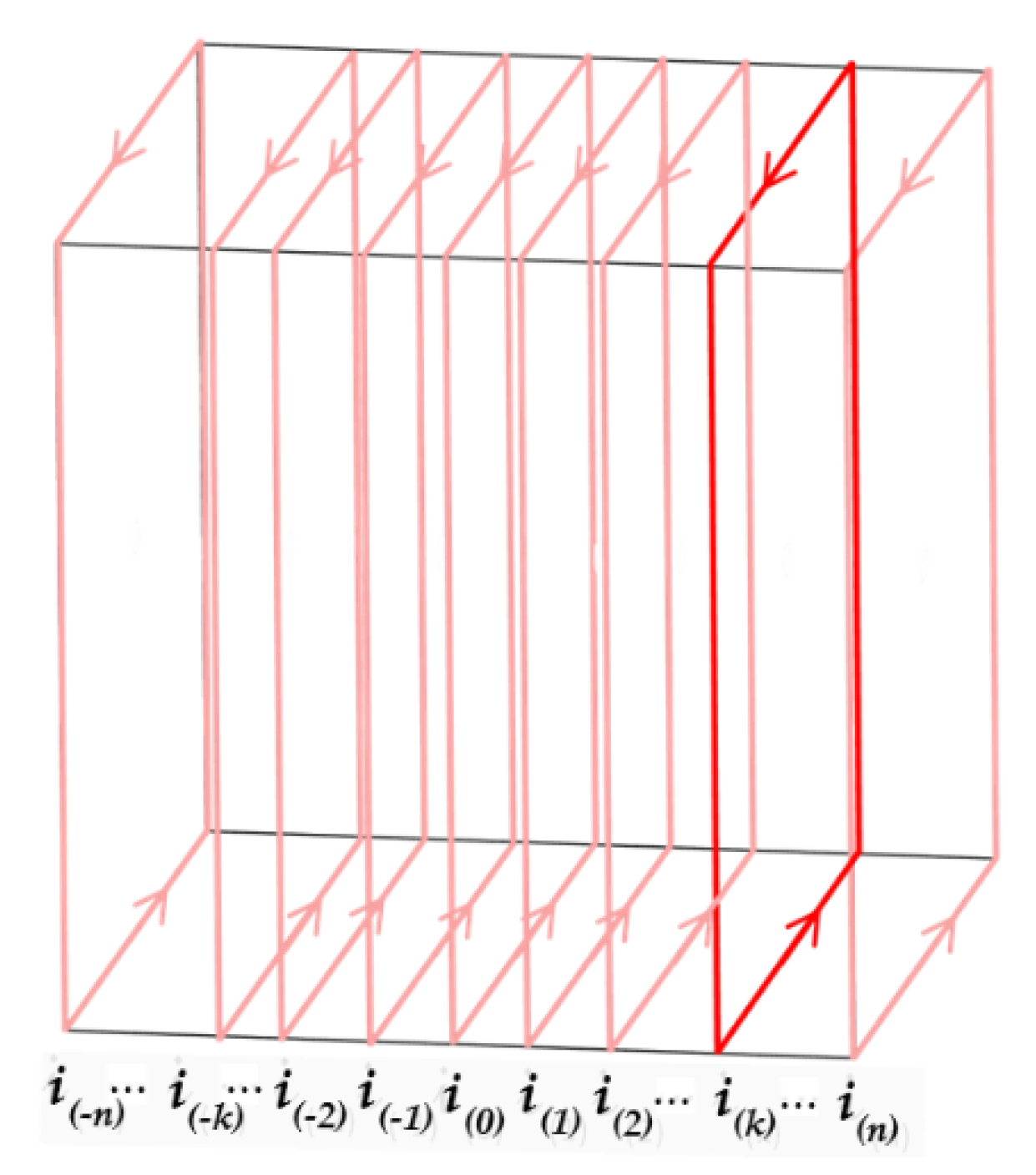
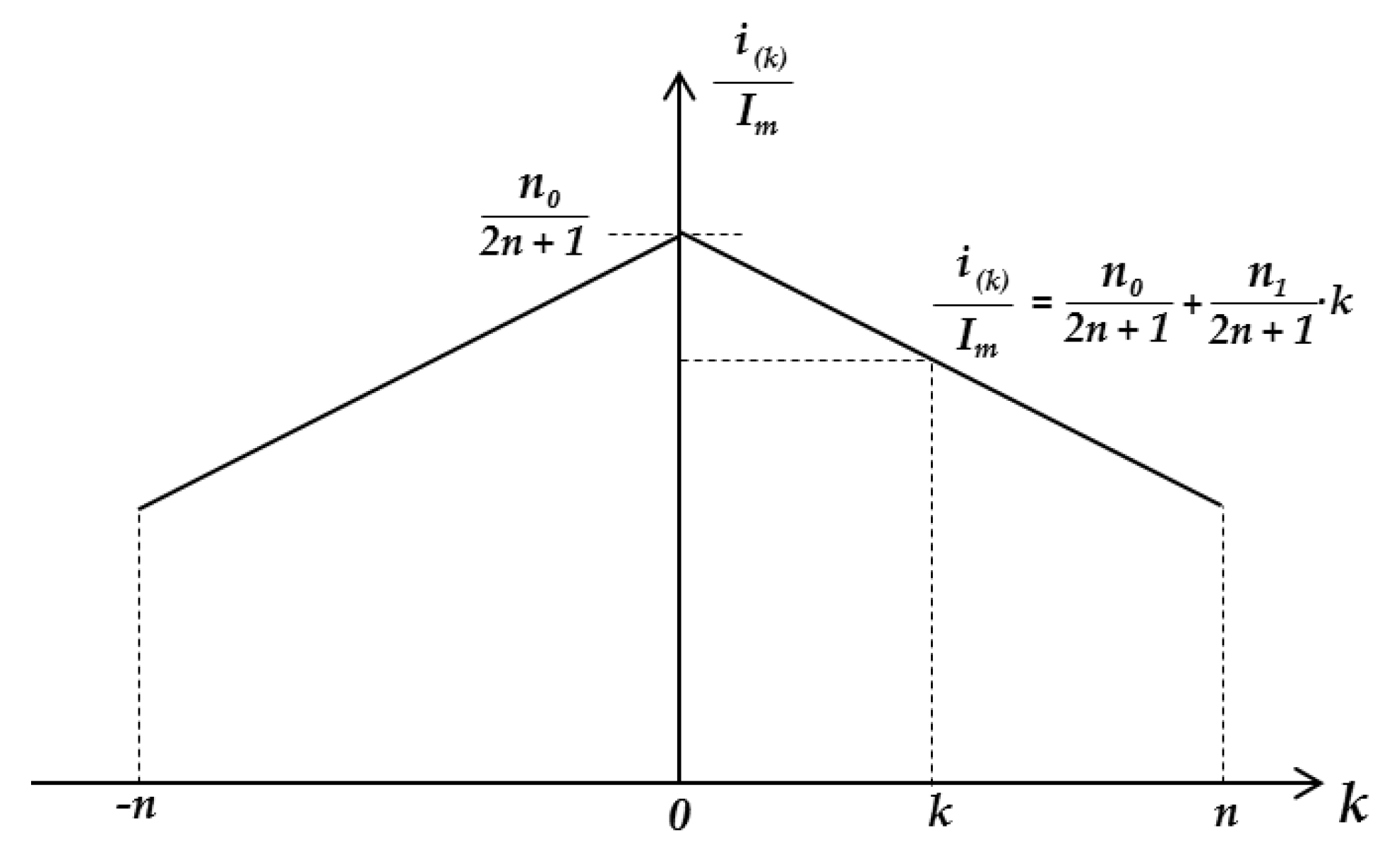
The mathematical modeling of a PM with the Ampere model can be derived using Figure 4. For the mathematical expression of i(k), Equation (3) is proposed in this paper by assuming the current distribution as a linear function of k, as shown in Figure 5. The total number of Amperian currents is 2n + 1, n0 and n1 are constant coefficients, and Im is the total sum of the currents.
i k = ( n 0 + n 1 | k | ) I m 2 n + 1
Im can be obtained using Equation (2).
Because the sum of i(k) is equal to Im, we can obtain Equation (4).
k = n k = n ( n 0 + n 1 | k | ) I m 2 n + 1 = I m
By rearranging Equation (4) for n0 and n1, we can derive Equation (5) for the constants n0 and n1.
n 1 = ( 2 n + 1 ) ( 1 n 0 ) n ( n + 1 )

3.4. Magnetic Field Analysis Using the AB Method

The magnetic flux density at a position that is at a distance r from the current flowing through the differential length dl can be obtained as Equation (6) by using the Biot–Savart law, where μ0 is the permeability of vacuum, I is the intensity of the current, and r ^ is a direction vector for an arbitrary position [34].
d B ( r ) = μ 0 I 4 π d l × r ^ r 2
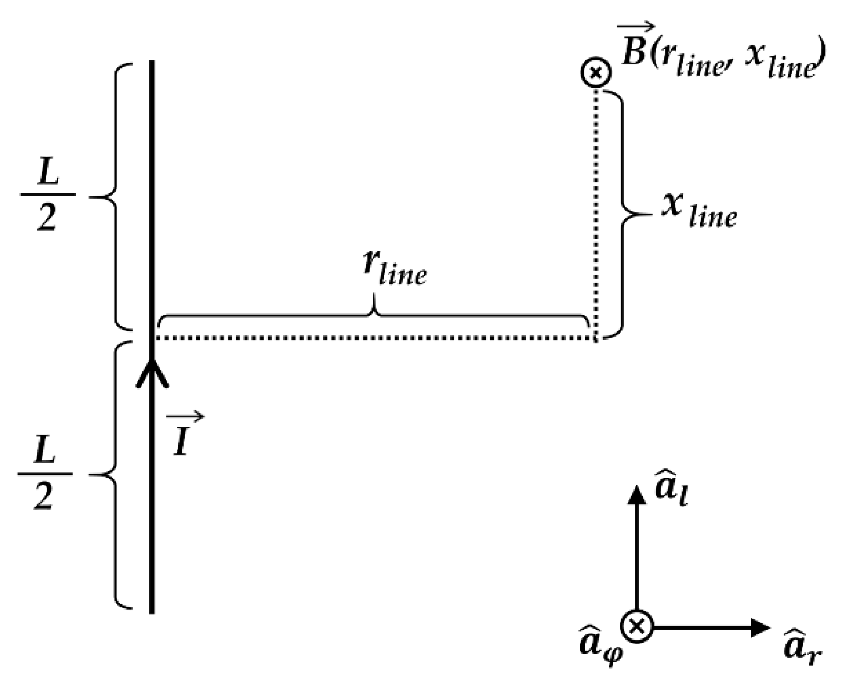
Figure 6 illustrates the magnetic flux density B( r l i n e , x l i n e ) at an arbitrary position that is at a vertical distance r l i n e and height x l i n e from the center point of the linear current I having finite length L. Based on Figure 6, Equation (7) is derived for the calculation of the magnetic flux density B( r l i n e , x l i n e ) generated by the line current I through the application of Equation (6) [34].
B ( r l i n e , x l i n e ) = μ 0 I 4 π r l i n e ( x l i n e + L / 2 r l i n e 2 + ( x + L / 2 ) 2 x l i n e L / 2 r l i n e 2 + ( x l i n e L / 2 ) 2 )
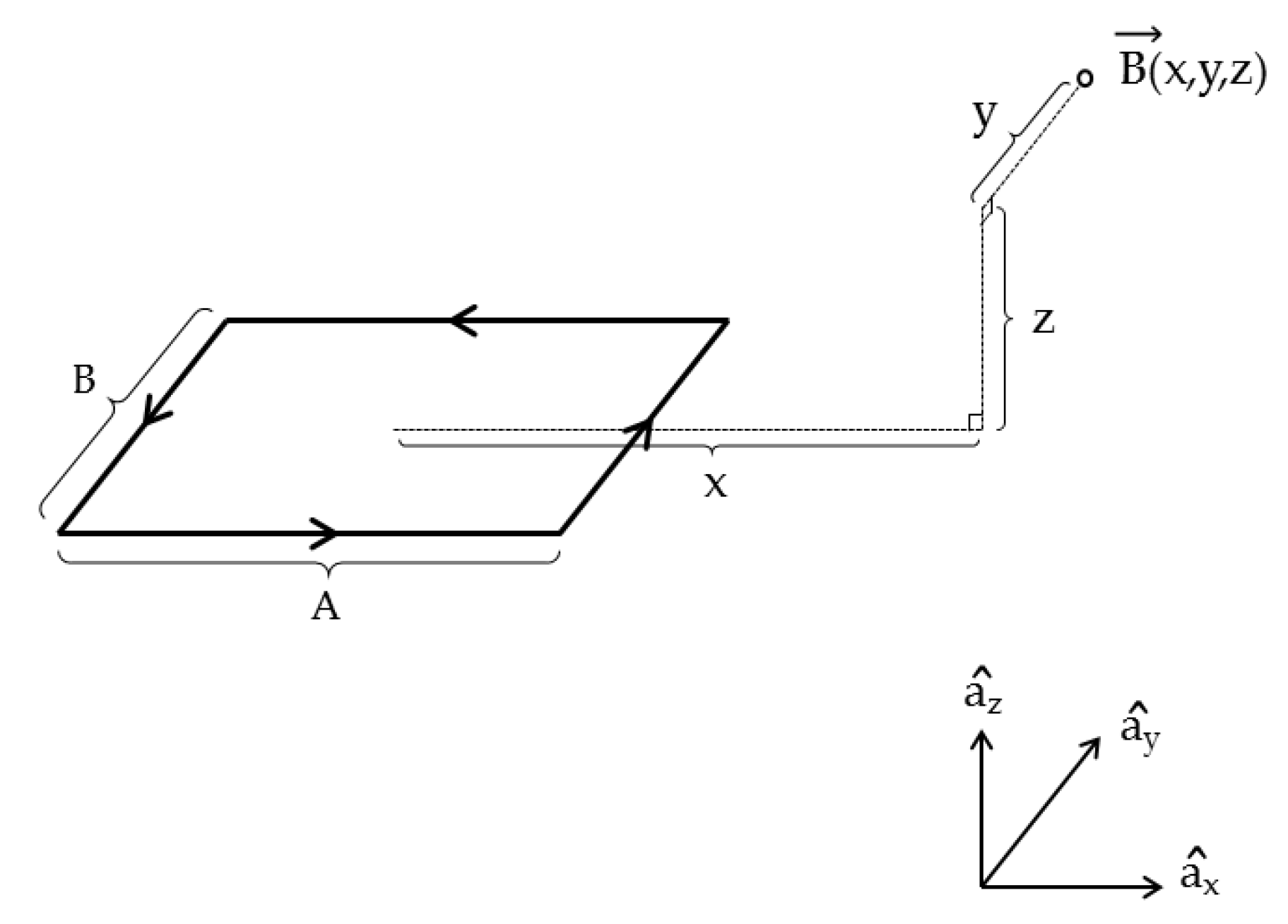
Figure 7 illustrates the vector Bloop(x,y,z) of the magnetic flux density from the current loop at a point (x,y,z) relative to the center point of the loop O. The current I flows through the loop, and loop has the width A and the length B. The function of Bloop(x,y,z) in Figure 7 can be derived as Equation (8) by applying Equation (7).
B l o o p ( x , y , z ) = B x a ^ x + B y a ^ y + B z a ^ z w h e r e B x = μ 0 I 4 π z ( x A 2 ) 2 + z 2 ( y + B 2 ( x A 2 ) 2 + z 2 + ( y + B 2 ) 2 y B 2 ( x A 2 ) 2 + z 2 + ( y B 2 ) 2 ) μ 0 I 4 π z ( x + A 2 ) 2 + z 2 ( y + B 2 ( x + A 2 ) 2 + z 2 + ( y + B 2 ) 2 y B 2 ( x + A 2 ) 2 + z 2 + ( y B 2 ) 2 ) B y = μ 0 I 4 π z ( y B 2 ) 2 + z 2 ( x + A 2 ( x + A 2 ) 2 + z 2 + ( y B 2 ) 2 x A 2 ( x A 2 ) 2 + z 2 + ( y B 2 ) 2 ) μ 0 I 4 π z ( y + B 2 ) 2 + z 2 ( x + A 2 ( x + A 2 ) 2 + z 2 + ( y + B 2 ) 2 x A 2 ( x A 2 ) 2 + z 2 + ( y + B 2 ) 2 ) B z = μ 0 I 4 π x + A 2 ( x + A 2 ) 2 + z 2 ( y + B 2 ( x + A 2 ) 2 + z 2 + ( y + B 2 ) 2 y B 2 ( x + A 2 ) 2 + z 2 + ( y B 2 ) 2 ) μ 0 I 4 π x A 2 ( x A 2 ) 2 + z 2 ( y + B 2 ( x A 2 ) 2 + z 2 + ( y + B 2 ) 2 y B 2 ( x A 2 ) 2 + z 2 + ( y B 2 ) 2 ) + μ 0 I 4 π y + B 2 ( y + B 2 ) 2 + z 2 ( x + A 2 ( x + A 2 ) 2 + z 2 + ( y + B 2 ) 2 x A 2 ( x A 2 ) 2 + z 2 + ( y + B 2 ) 2 ) μ 0 I 4 π y B 2 ( y B 2 ) 2 + z 2 ( x + A 2 ( x + A 2 ) 2 + z 2 + ( y B 2 ) 2 x A 2 ( x A 2 ) 2 + z 2 + ( y B 2 ) 2 )
By applying Equation (8) for the model of Figure 3b, the magnetic flux density vector B(x,y,z) at the position that is at (x,y,z) from the center of the bottom of PM can be derived as Equation (9).
B H a l b a c h ( x , y , z ) = B L e f t ( x , y , z ) + B C e n t e r ( x , y , z ) + B R i g h t ( x , y , z ) = k = n n { ( 1 0 0 0 1 0 0 0 1 ) B l o o p ( x + w 1 + w 2 2 , y , z t 2 t k 2 n ) + ( 0 0 1 0 1 0 1 0 0 ) B l o o p ( z + t 2 , y , x + w 2 k 2 n ) + ( 1 0 0 0 1 0 0 0 1 ) B l o o p ( x + w 1 + w 2 2 , y , z + t 2 t k 2 n ) }
where BLeft(x,y,z), BCenter(x,y,z), and BRight(x,y,z) each represent the vector of the magnetic flux density from the left magnet, the center magnet, and the right magnet in Figure 3.
Equation (9) can be simplified to Equation (10) when the magnetic flux density is calculated in the condition that x and y are zero. The magnetic flux density through the line where x and y are zero is calculated simply, and it is reasonable as a metric for the performance of HA at the initial design stage.
Based on the applied methods, the proposed analysis method is termed as the Ampere model and the Biot–Savart law analysis method (AB method) in this paper.
B ( z ) = k = n n μ 0 i k 4 π { z z 2 + ( k w 2 2 n ) 2 l z 2 + ( k w 2 2 n ) 2 + ( l 2 ) 2 + z + t ( z + t ) 2 + ( k w 2 2 n ) 2 l ( z + t ) 2 + ( k w 2 2 n ) 2 + ( l 2 ) 2 + l ( k w 2 2 n ) 2 + ( l 2 ) 2 z + t ( z + t ) 2 + ( k w 2 2 n ) 2 + ( l 2 ) 2 l ( k w 2 2 n ) 2 + ( l 2 ) 2 z z 2 + ( k w 2 2 n ) 2 + ( l 2 ) 2 + 2 ( k t 2 n + z + t 2 ) ( k t 2 n + z + t 2 ) 2 + ( w 2 2 ) 2 l ( k t 2 n + z + t 2 ) 2 + ( w 2 2 ) 2 + ( l 2 ) 2 + 2 ( k t 2 n + z + t 2 ) ( k t 2 n + z + t 2 ) 2 + ( w 2 + w 2 2 ) 2 l ( k t 2 n + z + t 2 ) 2 + ( w 2 + w 2 2 ) 2 + ( l 2 ) 2 }

4. Verification of the AB Method

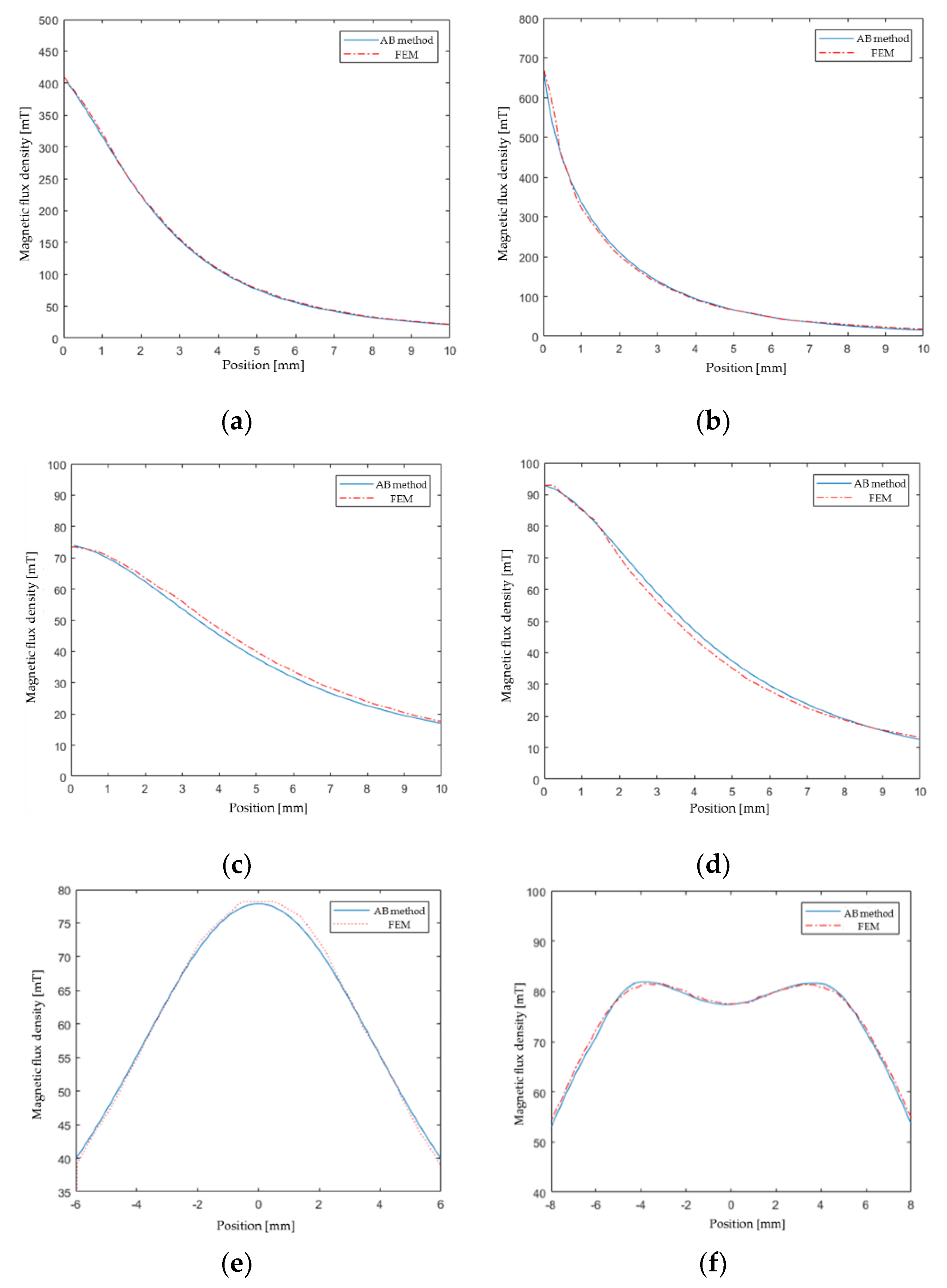
This study proposes the mathematical model and analytical method for the calculation of the magnetic flux density generated by the HA at an arbitrary position in an open area. For the verification of the proposed mathematical model and analysis method, a comparison of the magnetic flux density calculated by using both the proposed AB method and the finite element method (FEM) was carried out, as shown in Figure 8. The widely used arrangement of the HA, shown in Figure 3, is used for the verification model with data tabulated in Table 1.
As shown in Figure 8, the difference of the calculated magnetic flux density between the proposed AB method and FEM is within 8%. However, the calculation times are approximately 144 s and 50 ms, when using the FEM and AB method, respectively. The AB method used 21 current loops to create an equivalent circuit model for each permanent magnet. The FEM analysis was performed with 67,857 triangular elements which warrant grid-independence of the calculation results.
The optimal design of HA requires extensive trial and error with high time- and cost-consumption. When the optimal design of the HA is carried out by using FEM, the time and cost increase exponentially as the model of the HA is complex.
The proposed AB method does not require a lot of memory and time because it calculates the magnetic flux density only at the required position. Hence, when the proposed AB method is used for the optimal design of the HA; the time and cost can be reduced dramatically compared to the FEM, regardless of the complexity of the HA.
Moreover, the induced function of magnetic flux density of the AB method is differentiable and is itself an evaluation function of the objective function for the optimal design of the HA. Therefore, the general function of magnetic flux density derived with the AB method can be used simply and directly for the objective function of the optimization through the differentiation and using the gradient method. This facilitates a significant reduction in time and cost in the optimal design of the HA.
Briefly, the proposed AB method can reduce the memory, time, and cost required in the analysis and optimal design of the HA in an open area. Moreover, the AB method can be directly used for the objective function via simple differentiation and using the gradient method in the optimal design of the HA.

5. Conclusions

The existing mathematical models and analysis methods for the analysis of the HA in open space are not sufficient due to the condition that the device has no ferromagnetic core and has wide airgap. Hence, this research is significant in that it proposes the AB method, a novel mathematical model and rapid and accurate analytical method for the HA.
The proposed AB method contains the function for magnetic flux density defined by the design variables of the HA. Therefore, it is remarkable in that the relation between the design variables and characteristics of the HA can be estimated mathematically and directly via the AB method, and it makes the HA design procedure simpler.
The magnetic flux density generated by the Halbach array was derived as a function of three-dimensional space, which gives a continuous solution at any position in the space around HA. In addition, the proposed equation can be applied to HA with more complex structures, as well as to HA consisting of three permanent magnets presented in the manuscript, along with modification of the function depending on the structure.
In the analysis of the HA in open spaces by using FEM, many problems with respect to memory, time, and cost arise due to the increase in the number of mesh elements. Therefore, the rapid and accurate analysis of the HA being made possible with little memory usage by using the proposed AB method is noteworthy. These merits of the AB method compared to the FEM are augmented as the complexities of HA and open space are increased.
The optimal design requires many trial-and-error procedures. Hence, when the AB method is adopted in the optimization of HA, the memory, time, and cost decrease dramatically compared to when FEM is used. The derived magnetic flux density function of the AB method is differentiable, and it can offer additional indicators such as gradient and extremum to designer. Hence, its optimization can consider the magnetic characteristics of magnet array effectively and improve its optimization performance and efficiency.
Briefly, the proposed AB method is useful for reducing memory, time, and cost in the characteristic analysis and optimization of the HA. Hence, the AB method is useful and can be widely used in the analysis and optimal design of diverse types of electric machines, which use numerous arrangements and shapes of HAs. Moreover, the AB method can contribute to the development of diverse PM electric machines via the modification of its governing equations.

Author Contributions

Conceptualization, M.-S.S. and J.-S.R.; funding acquisition, J.-S.R.; investigation, M.-S.S.; methodology, M.-S.S. and J.-S.R.; project administration, J.-S.R.; resources, J.-S.R.; software, M.-S.S.; supervision, J.-S.R.; validation, M.-S.S.; visualization, M.-S.S.; writing—original draft, M.-S.S. and J.-S.R.; writing—review and editing, M.-S.S. and J.-S.R. All authors have read and agreed to the published version of the manuscript.

Funding

This work was funded by Basic Science Research Program through the National Research Foundation of Korea funded by the Ministry of Education (2016R1D1A1B01008058) and by the Chung-Ang University Research Grants in 2018.

Conflicts of Interest

The authors declare no conflict of interest.

References

  1. Halbach, K. Design of permanent multipole magnets with oriented rare earth cobalt material. Nucl. Instrum. Methods 1980, 169, 1–10. [Google Scholar] [CrossRef] [Green Version]
  2. Choi, J.S.; Yoo, J. Optimal design method for magnetization directions of a permanent magnet array. J. Magn. Magn. Mater. 2010, 322, 2145–2151. [Google Scholar] [CrossRef]
  3. Choi, J.-S.; Yoo, J. Design of a Halbach Magnet Array Based on Optimization Techniques. IEEE Trans. Magn. 2008, 44, 2361–2366. [Google Scholar] [CrossRef]
  4. Lee, J.; Nomura, T.; DeDe, E.M. Topology optimization of Halbach magnet arrays using isoparametric projection. J. Magn. Magn. Mater. 2017, 432, 140–153. [Google Scholar] [CrossRef]
  5. Ravaud, R.; Lemarquand, G. Comparison of the coulombian and ampe-rian current models for calculating the magnetic field produced by radially mag-netized arc-shaped permanent magnets. Prog. Electromagn. Res. 2009, 95, 309–327. [Google Scholar] [CrossRef] [Green Version]
  6. Shen, B.; Geng, J.; Li, C.; Zhang, X.; Fu, L.; Zhang, H.; Ma, J.; Coombs, T.A. Optimization study on the magnetic field of superconducting Halbach Array magnet. Phys. C Supercond. 2017, 538, 46–51. [Google Scholar] [CrossRef]
  7. Bjork, R.; Bahl, C.; Insinga, A.R. Topology optimized permanent magnet systems. J. Magn. Magn. Mater. 2017, 437, 78–85. [Google Scholar] [CrossRef] [Green Version]
  8. Insinga, A.R.; Bahl, C.; Bjork, R.; Smith, A. Reply to Comment on ‘Performance of Halbach magnet with finite coercivity’. J. Magn. Magn. Mater. 2017, 429, 386–389. [Google Scholar] [CrossRef]
  9. Liu, G.; Shao, M.; Zhao, W.; Ji, J.; Chen, Q.; Feng, Q. Modeling and analysis of halbach magnetized permanent-magnets machine by using lumped parameter magnetic circuit method. Prog. Electromagn. Res. M 2015, 41, 177–188. [Google Scholar] [CrossRef] [Green Version]
  10. Lee, M.G.; Lee, S.Q.; Gweon, D.-G. Analysis of Halbach magnet array and its application to linear motor. Mechatronics 2004, 14, 115–128. [Google Scholar] [CrossRef]
  11. Jian, L.; Chau, K.T. Design and Analysis of an Integrated Halbach-magnetic-geared Permanent-magnet Motor for Electric Vehicles. J. Asian Electr. Veh. 2009, 7, 1213–1219. [Google Scholar] [CrossRef] [Green Version]
  12. Jin, P.; Yuan, Y.; Xu, Q.; Fang, S.; Lin, H.; Ho, S.L. Analysis of Axial-Flux Halbach Permanent-Magnet Machine. IEEE Trans. Magn. 2015, 51, 1–4. [Google Scholar] [CrossRef]
  13. Dwari, S.; Parsa, L.; Karimi, K.J. Design and analysis of Halbach array permanent magnet motor for high acceleration applications. IEEE Int. Electr. Mach. Drives Conf. 2009, 2, 1100–1104. [Google Scholar]
  14. Dwari, S.; Parsa, L. Design of Halbach-Array-Based Permanent-Magnet Motors with High Acceleration. IEEE Trans. Ind. Electron. 2011, 58, 3768–3775. [Google Scholar] [CrossRef]
  15. Mallek, M.; Tang, Y.; Lee, J.; Wassar, T.; Franchek, M.; Pickett, J. An Analytical Subdomain Model of Torque Dense Halbach Array Motors. Energies 2018, 11, 3254. [Google Scholar] [CrossRef] [Green Version]
  16. HAN, Q. Analysis and Modeling of the Eds Maglev System Based on the Halbach Permanent Magnet Array; University of Central Florida: Orlando, FL, USA, 2004. [Google Scholar]
  17. Ham, C.; Ko, W.; Han, Q. Analysis and optimization of a Maglev system based on the Halbach magnet arrays. J. Appl. Phys. 2006, 99, 3–5. [Google Scholar] [CrossRef] [Green Version]
  18. Jin, Y.; Kou, B.; Zhang, L.; Zhang, H.; Zhang, H. Magnetic and thermal analysis of a Halbach Permanent Magnet eddy current brake. Int. Conf. Electr. Mach. Syst. 2016, 2017, 5–8. [Google Scholar]
  19. Gonzalez, M.I. Experiments with eddy currents: The eddy current brake. Eur. J. Phys. 2004, 25, 463–468. [Google Scholar] [CrossRef]
  20. Ma, D.-M.; Shiau, J.-K. The design of eddy-current magnet brakes. Trans. Can. Soc. Mech. Eng. 2011, 35, 19–37. [Google Scholar] [CrossRef]
  21. Ebrahimi, B.; Khamesee, M.B.; Golnaraghi, F. A novel eddy current damper: Theory and experiment. J. Phys. D Appl. Phys. 2009, 42, 075001. [Google Scholar] [CrossRef]
  22. Ebrahimi, B.; Khamesee, M.B.; Golnaraghi, F. Eddy current damper feasibility in automobile suspension: Modeling, simulation and testing. Smart Mater. Struct. 2008, 18, 15017. [Google Scholar] [CrossRef]
  23. Eckert, P.R.; Filho, A.F.F.; Perondi, E.; Ferri, J.; Goltz, E. Design Methodology of a Dual-Halbach Array Linear Actuator with Thermal-Electromagnetic Coupling. Sensors 2016, 16, 360. [Google Scholar] [CrossRef] [PubMed] [Green Version]
  24. Meessen, K.; Gysen, B.; Paulides, J.; Lomonova, E. Halbach Permanent Magnet Shape Selection for Slotless Tubular Actuators. IEEE Trans. Magn. 2008, 44, 4305–4308. [Google Scholar] [CrossRef] [Green Version]
  25. Choi, Y.-M.; Lee, M.G.; Gweon, D.-G.; Jeong, J. A new magnetic bearing using Halbach magnet arrays for a magnetic levitation stage. Rev. Sci. Instrum. 2009, 80, 45106. [Google Scholar]
  26. Eichenberg, D.J.; Gallo, C.A.; Thompson, W.K. Development and Testing of an Axial Halbach Magnetic Bearing; Technical Report, NASA/TM-2006-214477, E-15769; NASA: Washington, DC, USA, 2006. [Google Scholar]
  27. Feipeng, X.; Tiecai, L.; Yajing, L. A Study on passive magnetic bearing with Halbach magnetized array. In Proceedings of the 2008 International Conference on Electrical Machines and Systems, Wuhan, China, 17–20 October 2008; pp. 417–420. [Google Scholar]
  28. Zhu, D.; Beeby, S.; Tudor, J.; Harris, N. Vibration energy harvesting using the Halbach array. Smart Mater. Struct. 2012, 21, 75020. [Google Scholar] [CrossRef]
  29. Behnke, C.; Schomburg, W.K. Energy Harvesting for Sensors of Structural Integrity in Wind Power Stations. Proceedings 2017, 1, 577. [Google Scholar] [CrossRef] [Green Version]
  30. Xu, Q.R.; Send, R.; Paprotny, I.; White, R.M.; Wright, P.K. Miniature self-powered stick-on wireless sensor node for monitoring of overhead power lines. In Proceedings of the 2013 IEEE Energy Conversion Congress and Exposition, Denver, CO, USA, 15–19 September 2013; pp. 2672–2675. [Google Scholar]
  31. He, W.; Li, P.; Wen, Y.; Zhang, J.; Lu, C.; Yang, A. Energy harvesting from electric power lines employing the Halbach arrays. Rev. Sci. Instrum. 2013, 84, 105004. [Google Scholar] [CrossRef]
  32. Vinuesa, R.; Azizpour, H.; Leite, I.; Balaam, M.; Dignum, V.; Domisch, S.; Felländer, A.; Langhans, S.D.; Tegmark, M.; Nerini, F.F. The role of artificial intelligence in achieving the Sustainable Development Goals. Nat. Commun. 2020, 11, 1–10. [Google Scholar] [CrossRef] [Green Version]
  33. Fitzgerald, A.E.; Kingsley, C.; Umans, S.D. Electric Machinery, 6th ed.; McGraw-Hill Higher Education: New York, NY, USA, 2003; ISBN 0073660094. [Google Scholar]
  34. Binns, K.J.; Lawrenson, P.J.; Trowbridge, C.W. The Analytical and Numerical Solution of Electric and Magnetic Fields, 1st ed.; Wiley: Hoboken, NJ, USA, 1993; ISBN 978-0-471-92460-9. [Google Scholar]
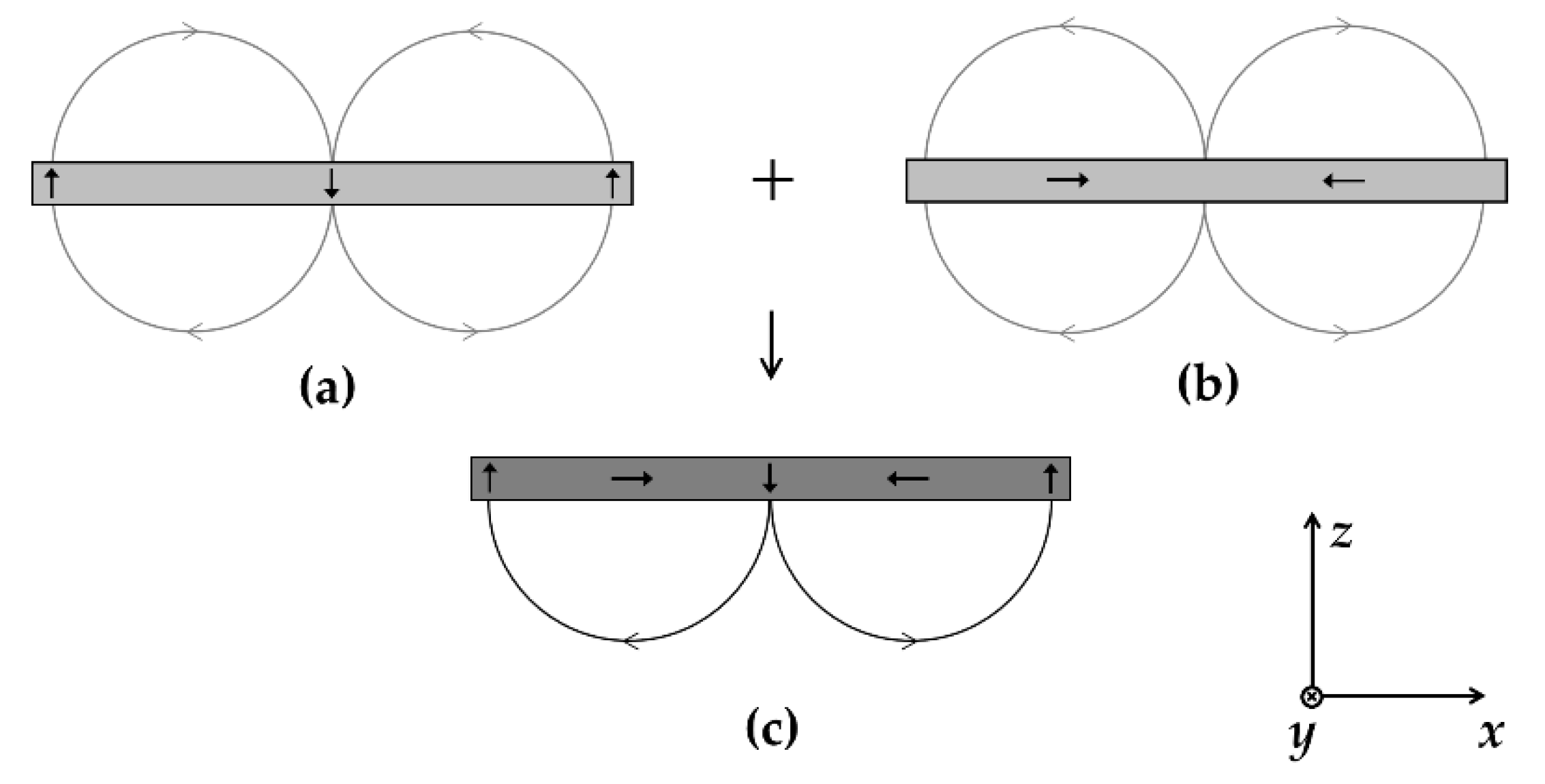
Figure 1. (a) PM arrays magnetized in the +z and −z direction; (b) permanent magnet (PM) arrays magnetized in +x and −x direction; (c) Halbach array (HA) through the combination of (a) and (b).
Energies 13 01252 g001
Figure 2. Assumption of PM as (a) an Ampere model and (b) a Gilbert model, where : Amperian current, of which flowing direction is into the page; ⊙: Amperian current, of which flowing direction is out of the page; : North-pole of the magnetic charge; ⊖: South-pole of the magnetic charge.
Energies 13 01252 g002
Figure 3. (a) Arrangement of the HA for the verification of the proposed analytical method where the magnetized direction is represented by ⇨; (b) Modeling of the HA with the distributed currents by applying the Amperian model.
Energies 13 01252 g003
Figure 4. Modeling of a PM shown in Figure 3b with the Amperian model by using distributed currents, where i(k) is the k-th current.
Energies 13 01252 g004
Figure 5. The plot of the Amperian current distribution of Figure 4 with the linear function.
Energies 13 01252 g005
Figure 6. Illustration of the magnetic flux density B( r l i n e , x l i n e ) at the position ( r l i n e , x l i n e ) by the line current I with a finite length L.
Energies 13 01252 g006
Figure 7. Illustration of the magnetic flux density vector Bloop(x,y,z) at the position (x,y,z) by the rectangular current loop of the current I.
Energies 13 01252 g007
Figure 8. Comparison between the proposed AB method and the FEM via the calculated magnetic flux density data of the model demonstrated in Figure 3: (a) when z varies from 0 to 10 mm with (x,y) fixed at (0,0); (b) when z varies from 0 to 10 mm with (x,y) fixed at (5, −2.5); (c) when z varies from 0 to 10 mm with (x,y) fixed at (0,−6); (d) when z varies from 0 to 10 mm with (x,y) fixed at (10,0); (e) when y varies from −6 to 6 mm with (x,z) fixed at (0,5); (f) when x varies from −8 to 8 mm with (y,z) fixed at (0,5).
Energies 13 01252 g008
Table 1. Design variable and material properties of the HA for the verification of the AB method.
Design VariableValue
w15 mm
w25 mm
l5 mm
t5 mm
μr1.0998
Hc−890 kA/m