Article

Decentralized Control Method of ISOP Converter for Input Voltage Sharing and Output Current Sharing in Current Control Loop

Department of Electrical and Computer Engineering, Sungkyunkwan University, Suwon 16419, Korea
*
Author to whom correspondence should be addressed.
Energies 2020, 13(5), 1114; https://doi.org/10.3390/en13051114
Submission received: 7 February 2020 / Revised: 21 February 2020 / Accepted: 26 February 2020 / Published: 2 March 2020
(This article belongs to the Section F: Electrical Engineering)

Abstract

:
Input-Series-Output-Parallel (ISOP) converters, a kind of modular converter, are used in high-input voltage and high-output current applications. In ISOP converters, Input Voltage Sharing (IVS) and Output Current Sharing (OCS) should be implemented for stable operation. In order to solve this problem, this paper proposes a decentralized control method. In the proposed control, output current reference is changed according to the decentralized control characteristic in individual current control loops. In this way, the proposed control method is able to implement IVS and OCS without communication. Also, this method can be easily used in current control loops and has high reliability compared to conventional control methods that require communication. In this paper, the operation principle is described to elucidate the proposed control and a small signal model of an ISOP converter is also implemented. Based on the small signal model, IVS stability analysis is performed using pole-zero maps with varying coefficients and control gains. In addition, the current control loop is designed in a stable region. In order to demonstrate the proposed control method, a prototype ISOP converter is configured using full-bridge converters. The performance of IVS and OCS in an ISOP converter is verified by experimental result.

1. Introduction

As the capacity of converters increases, the importance of modular converters increases, because modular converters have high reliability and flexibility [1,2]. A modular converter in which the inputs are connected in series and the outputs are connected in parallel is known as an Input-Series-Output-Parallel (ISOP) converter. The variable advantages of ISOP converter are introduced: first, ISOP converter has a simple thermal design due to the power distribution of the modules; second, it exhibits increased system reliability and low electrical stresses for power semiconductors; third, its simple design means the components of the system have a low cost; fourth, it is easy to expand its power for a converter [3,4]. Therefore, ISOP converters have advantages for configurations that require a high-input voltage and high-output current. The series connection reduces the input voltage stress and the parallel configuration makes a low output current in each module [5,6]. However, modular converters require accurate power sharing because of parameter mismatch in individual modules. In addition, higher voltage and larger input capacitance is required with unbalanced power between modular converters. This results in the high cost and low power density of ISOP converters. Therefore, power balance is the main issue in modular converters for proper operation between the modules. In order to promote proper operation in ISOP converters, accurate Input Voltage Sharing (IVS) and Output Current Sharing (OCS) are required due to input series and output parallel connections [7,8].
For IVS and OCS, various control methods, from simple to complex ones, have been proposed for power sharing in ISOP converters [8,9,10,11,12,13,14,15,16,17,18,19,20,21,22,23]. A control method using common duty-ratio control has been implemented without any additional control loops [8,9]. Common duty-ratio control was used in forward and phase-shift full-bridge converters, where all modules are controlled with the same duty from a single controller. A control method using a sensorless current mode has also been proposed in [10]. Both control methods have the advantage that they can be implemented in IVS and OCS using simple structure control. However, both control methods have difficulties controlling IVS and OCS accurately.
Therefore, control methods have been proposed with additional control loops to perform more accurate IVS and OCS. Specifically, control methods using the input voltage of each module and an additional output voltage regulation loop (OVR) have been used in [11,12,13]. This control method can be used for various connections, such as ISOP, Input-Parallel-Output-Parallel (IPOP) and Input-Series-Output-Series (ISOS). IVS and OCS are implemented easily with this additional single control loop. However, this control method is specialized in the voltage control loop. As a result, it is difficult to use in ISOP converters with current control loops. In [14], an input voltage feedforward control was proposed. The feedforward control method uses input voltage deviation between two modules, but this control method exchanges the individual input voltage state using communication. In [15], a master–slave control for a modular converter was studied. This control method realizes that output voltage is controlled by a master module, while input voltage and output current are controlled by slave modules. IVS and OCS control and modulation methods were proposed for indirect input-series output-parallel (I2SOP) converters. This method can only be used for I2SOP converters [16].
In order to implement IVS and OCS without needing the control of the input voltage, control methods using control variables of each converter have been studied [17,18]. In [17], cross feedback control using current feedback of other modules in the ISOP converter was used. IVS and OCS were implemented without additional control loops by controlling duty through cross current feedback. In [18], a duty cycle exchanging control method was used. This control method works by exchanging the duty of each converter module. In a previous paper, a stability analysis of IVS was performed to prove the validity of this control method and control loop design was performed. In addition, a decoupled control method was proposed for DAB in ISOP connection [19]. The input voltage and output voltage control loop is decoupled between modules. However, these control methods have complicated control loops.
The ISOP converter was controlled using the peak current control method in [20]. This method is a suitable control method for topologies with wide variable input voltage ranges. An output current differential control method was proposed and compared with other control methods in [21]. This output current differential control method proved to have good IVS performance in all load ranges and a control loop design, stability analysis were also performed.
Various control methods mentioned in previous papers were controlled using communication between the modules of ISOP converters. However, performing IVS and OCS is difficult when communications are disconnected. Therefore, the reliability of ISOP converter is affected by this communication. In order to increase reliability, decentralized control methods have been proposed for ISOP converters [22,23]. A positive output voltage gradient method was used to perform IVS and OCS using the state of input and output voltages [22]. As the output voltage reference is changed differently according to individual input voltage, IVS and OCS can be implemented without communication. As a result, the modules of the ISOP converter have a different duty according to the state of input voltage. Decentralized inverse droop control was used in parallel operations in [23]. This droop control has positive coefficients and uses output current and input voltage. However, previously decentralized control methods have a disadvantage in that control method can only be used in output voltage control loops. To perform current control, conventional controls need a double control loop for IVS and OCS. Decentralized control methods for current control loop have not yet been proposed. Therefore, a decentralized control method with a current control loop needs to be studied and a stability analysis of an ISOP converter with this control method should be required for future study.
This paper proposes a decentralized control method that changes output current reference according to the input voltage. In the proposed control method, individual output current is changed using its own current feedback and total output current and can be maintained with a low transient current. In the proposed control method based on droop control, the power balancing response is later than the conventional method using communication. However, using the proposed control method, IVS and OCS can be implemented simultaneously without communication between two modules. In addition, this method gives ISOP converters higher reliability because the ISOP converter is controlled without the need for communication in current control loop. Also, since direct feedback is applied into the current control loop, the control loop for voltage can be a reduced loop, such as a grid-connected converter in a DC microgrid.
In this paper, the operation principles of ISOP converters and the proposed control method are described and small signal modeling is performed. Based on the small signal model of an ISOP converter, input voltage stability with the proposed control method is analyzed in changed coefficients and PI controller gain. In addition, a stable current control loop is designed for the individual control loop. Finally, the performance of the proposed control method is verified through experiment.

2. Decentralized Control Method

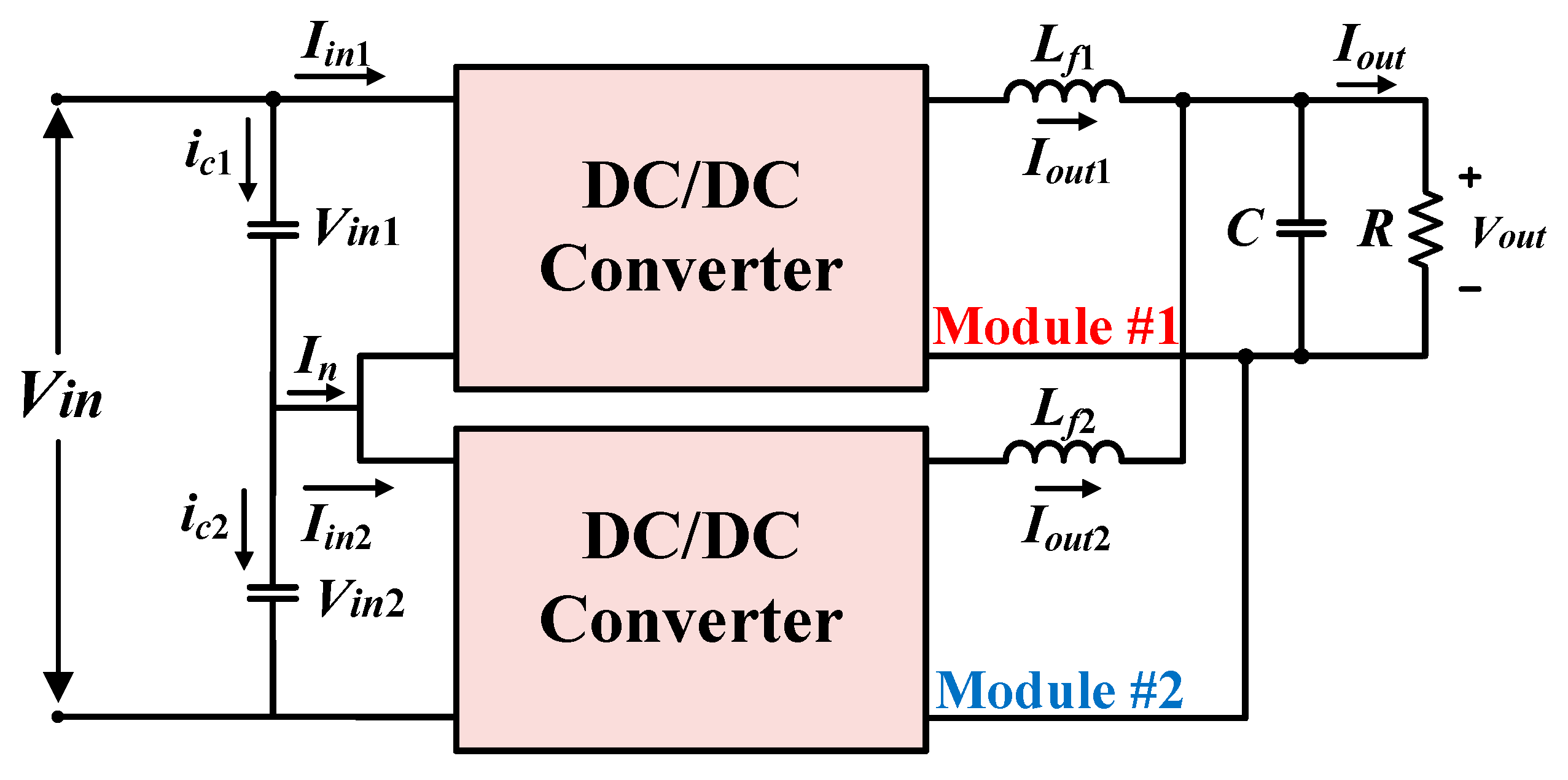
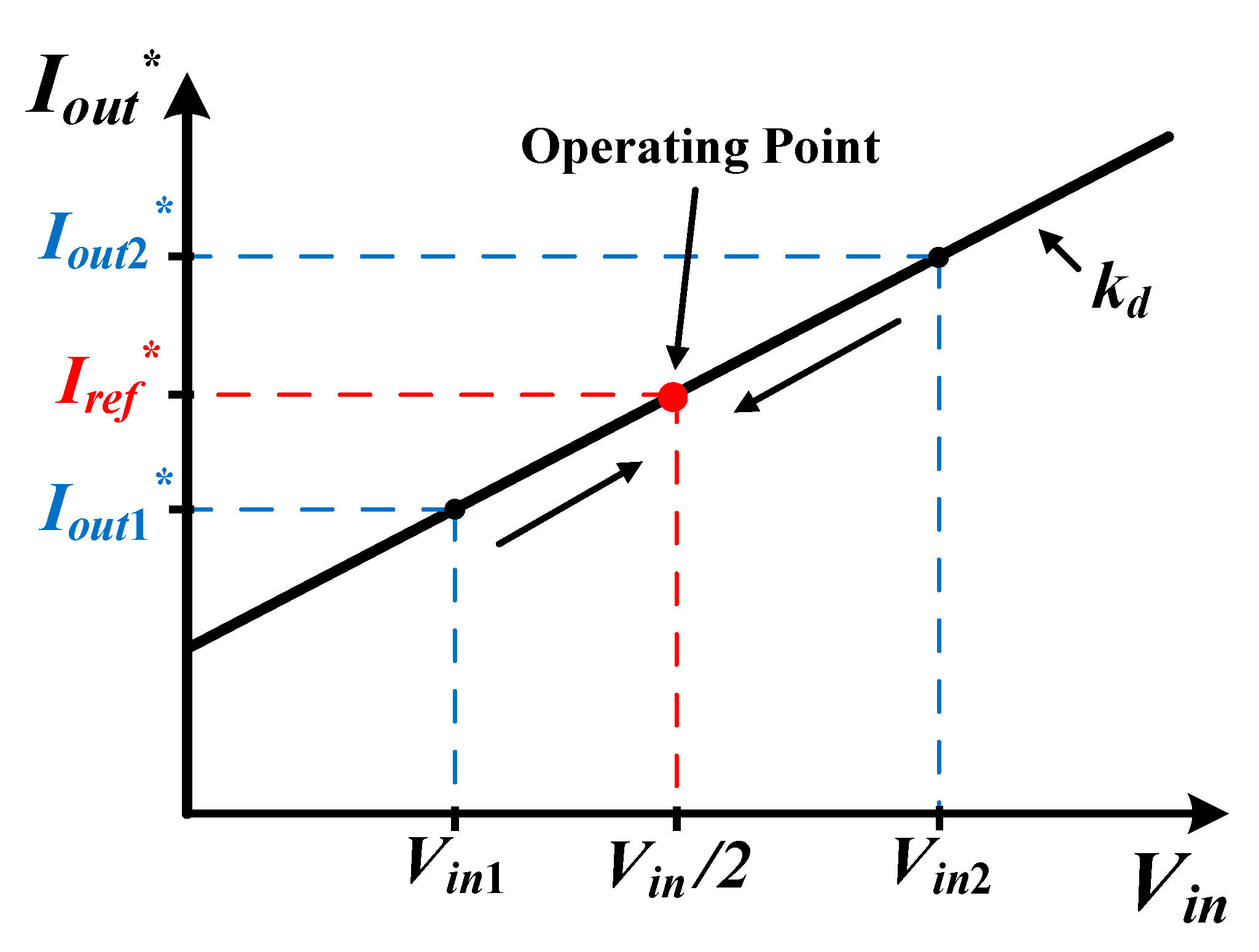
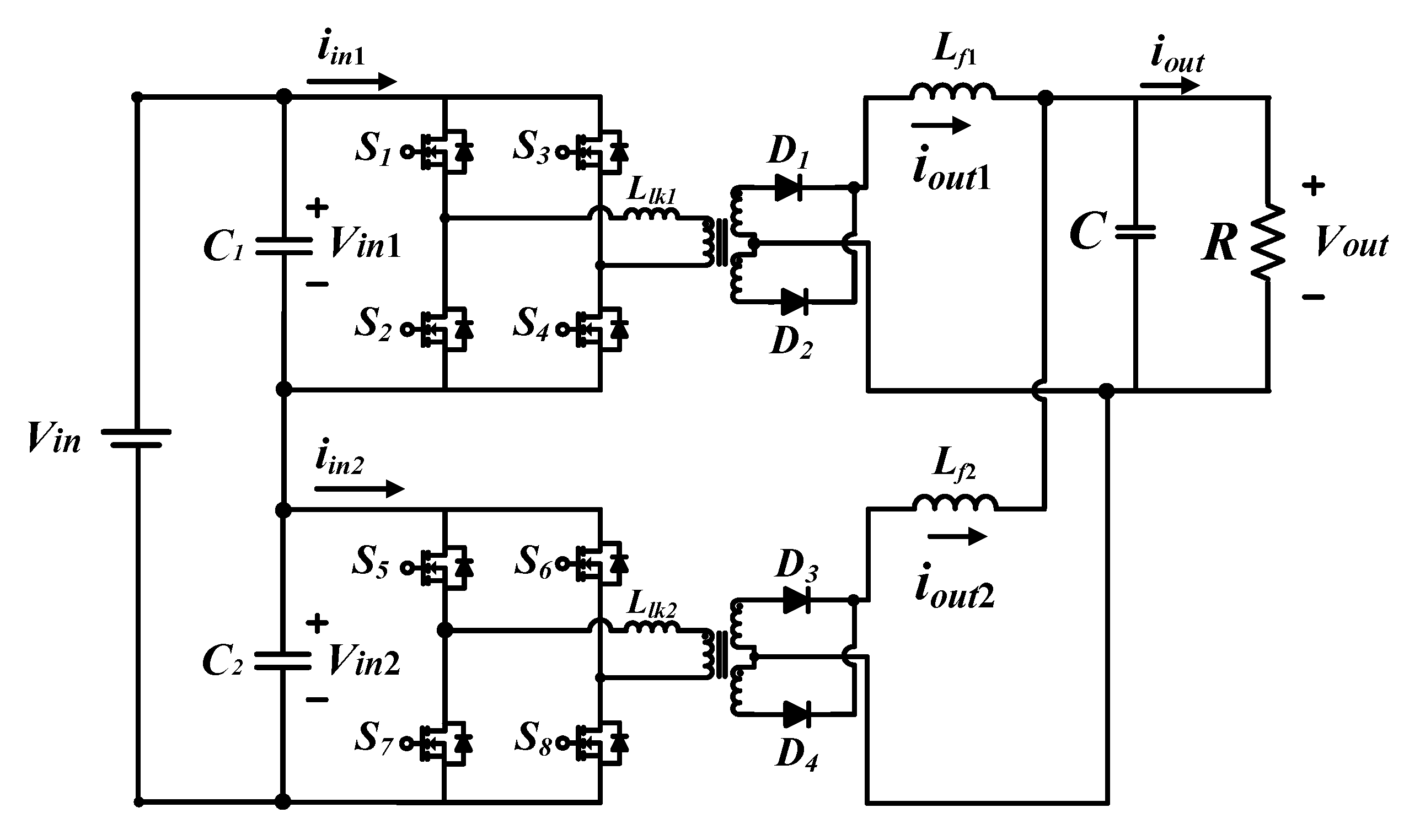
2.1. Operation Principle of Decentralized Control Method

In order to understand decentralized control methods, operation principles of ISOP converters are described in this chapter. Figure 1 shows the configuration of a simplified ISOP converter. Vin is the total input voltage, Vin1 and Vin2 are the input voltages of each module. Vin is divided in to Vin1 and Vin2 because of the series connected capacitor. Total output current Iout is composed of individual output currents, Iout1 and Iout2, which is explained by the parallel connection.
In order to explain the operation principle, it is assumed that the total input current and voltage are not changed in the ISOP converter. When Iout1 increases, Iin1 increases because Iout1 and Iin1 are proportional due to the transformer. On the other hand, when Iout2 decreases then Iin2 decreases. When Vin2 increases and Vin1 decreases, negative current flows through In because of the difference in input current at each module. According to previous operations, when the output current Iout1 increases, the input voltage Vin1 decreases as shown in Figure 2. On the contrary, when Iout1 decreases, Iin1 decreases. On the other hand, when Iout2 increases then Iin2 increases. Therefore, when Vin1 increases and Vin2 decreases, a positive current flows through In. As a result, when the output current Iout2 increases, the input voltage Vin2 decreases. Individual powers P1 and P2 are written as:
P 1 = V i n 1 I i n 1 V o u t I o u t 1
P 2 = V i n 2 I i n 2 V o u t I o u t 2
Based on the operation of the ISOP converter shown in Figure 2, the operation principle that input voltage can be controlled by changing the output can be understood. Using this operation principle, a decentralized control method is proposed in the next section.

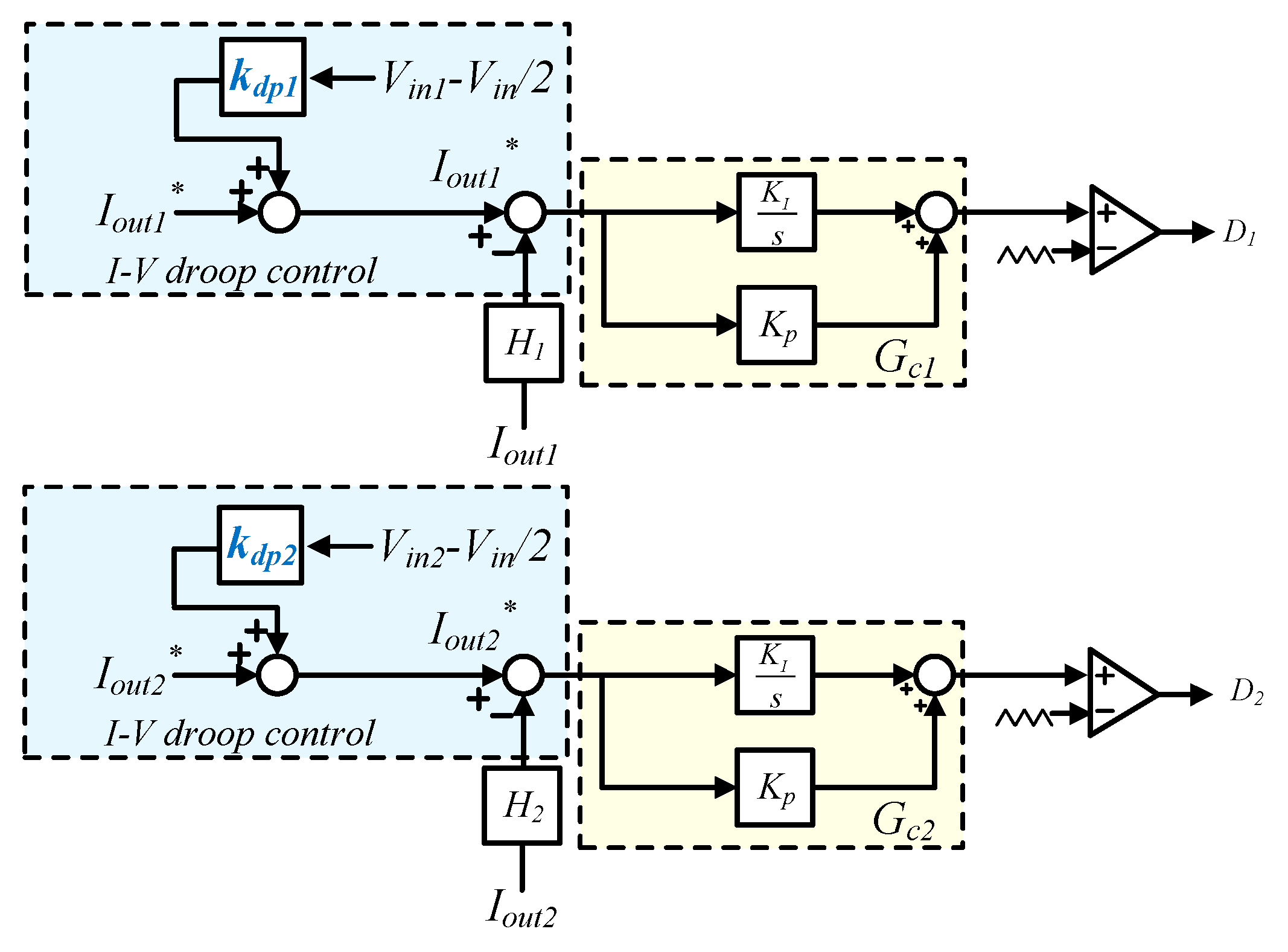
2.2. Proposed Decentralized Control Method

Based on the operation principles described above, this paper proposes a decentralized control method. This decentralized control characteristics are shown in Figure 3. Iout1* and Iout2* are the output current references of each module. To implement IVS and OCS in an ISOP converter, this decentralized control method changes the output current reference according to the input voltage state of each module. In order to explain the operation, Figure 3 assumes that the two modules have different input voltage conditions and the same characteristics. When the input voltage of module #2, Vin2, is high, then the input voltage of module #1, Vin1, is low. Iout2* is increased and Iout1* is decreased according to the characteristics. Therefore, Vin2 is decreased as Iout2 is increased and Vin1 is increased as Iout1 is decreased based on these operation principles.
Through the described operation, individual input voltages and output current references are moved to the operating point in a transient state. Also, total output current fluctuation is low due to the same characteristics. As a result, IVS and OCS can be implemented in steady state. The characteristics of decentralized control are expressed by:
I o u t 1 = I r e f + k d p 1 ( V i n 1 V i n / 2 )
I o u t 2 = I r e f + k d p 2 ( V i n 2 V i n / 2 )
kdp1 and kdp2 are the control coefficients of each module. In order to implement stable operation, an appropriate coefficient should be chosen considering the maximum output current of the system because control characteristics vary with coefficient. Also, the turn ratio of the transformer should be considered, as the transient response varies with the turn ratio.

3. Stability Analysis of ISOP Converter with Proposed Control Method

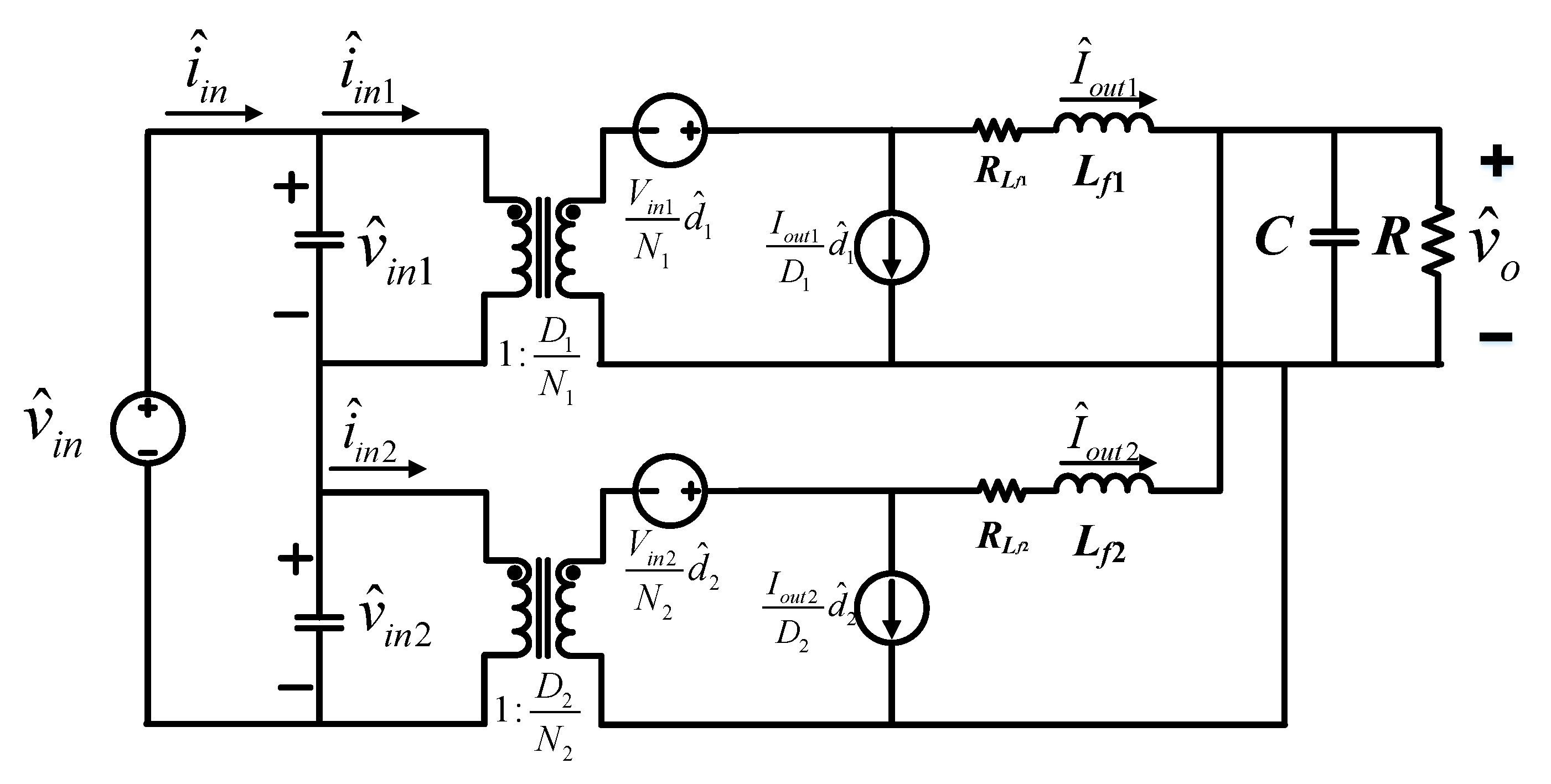
3.1. Small Signal Modeling of ISOP Converter

Small signal modeling of an ISOP converter is implemented before performing IVS stability analysis with the proposed control method. Figure 4 shows the configuration of the ISOP converter. The ISOP converter consists of the full-bridge converter at each module and uses a center-tap transformer.
The small signal equivalent circuit model of the ISOP converter, as shown in Figure 5, is calculated based on Figure 4. In Figure 5, d ^ 1 and d ^ 2 are perturbations of the duty ratio d 1 and d 2 in each module. i ^ i n 1 and i ^ i n 2 are perturbations of the individual input currents. i ^ o u t 1 and i ^ o u t 2 are perturbations of the individual output currents. v ^ i n and v ^ o are perturbations of total input voltage and total output voltage. D1 and D2 are duty ratio in a steady state. R is rated load. Iout1, Iout2 are individual output current and Vin1, Vin2 are individual input voltage.
The ISOP converter consists of a multi-module converter. However, this paper relies on two modules of the ISOP converter having same input capacitance, output inductance and capacitance as well as turn ratio in a steady state for analysis. Also, it is assumed that the input voltage and output current of each module are the same in a steady state.
Based on the small signal equivalent circuit of the ISOP converter, the following equations using KCL and KVL are obtained:
D 1 N 1 v ^ i n 1 + V i n 1 N 1 d ^ 1 = s L f 1 i ^ o u t 1 + v ^ o
D 2 N 2 v ^ i n 2 + V i n 2 N 2 d ^ 2 = s L f 2 i ^ o u t 2 + v ^ o
N 1 D 1 i ^ i n 1 = I o u t 1 D 1 d ^ 1 + i ^ o u t 1
N 2 D 2 i ^ i n 2 = I o u t 2 D 2 d ^ 2 + i ^ o u t 2
As the output of the ISOP converter is connected in parallel, the perturbation of total output voltage is expressed as:
v ^ o = R o R o C s + 1 ( i ^ o u t 1 + i ^ o u t 2 )
The small signal modeling of the ISOP converter is implemented for the stability analysis of proposed control method.

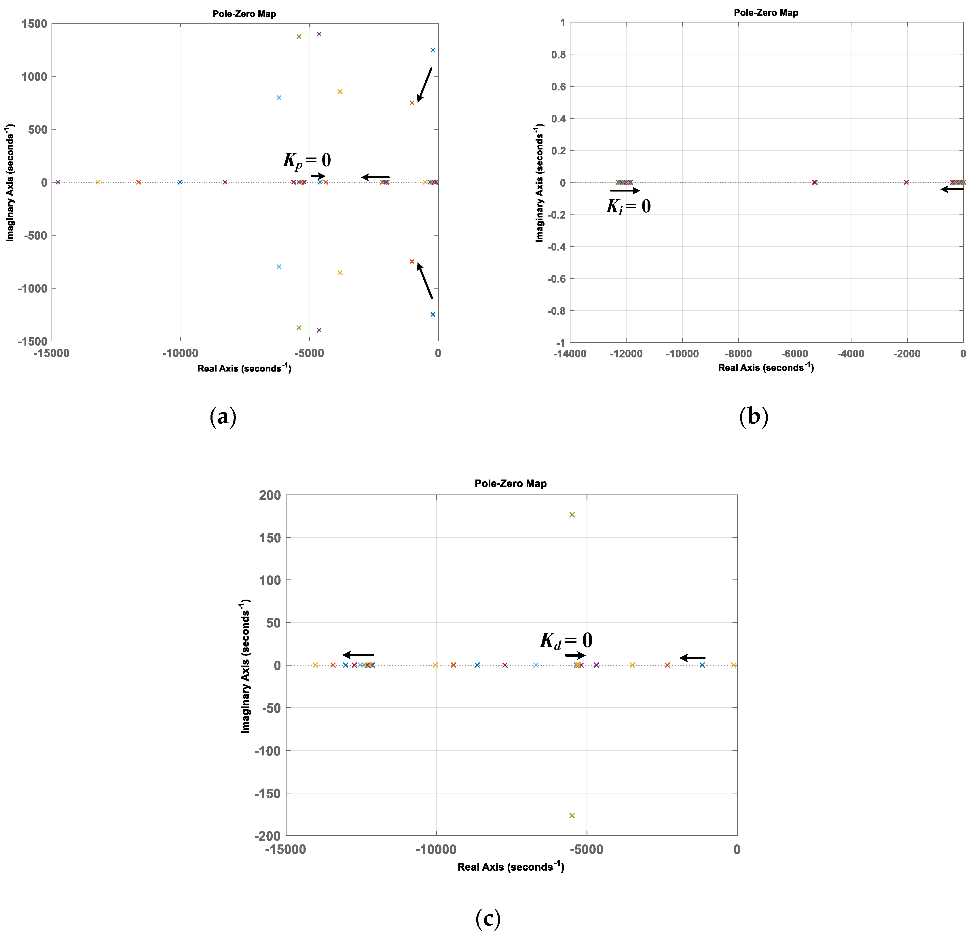
3.2. Stability Analysis of Proposed Control Method

In this section, the stability analysis of the proposed control method is implemented using the small signal modeling of the ISOP converter. To verify the stability of the IVS in an ISOP converter, each DC–DC converter module is replaced by an equivalent impedance in parallel with an input capacitor for each module [14,17,18]. Using the equivalent impedance of a module, the transfer function of the input voltage difference to the total input voltage is analyzed to verify stability.
Figure 6 shows control block diagrams of the ISOP converter. (12) and (13) are the transfer functions of individual output current controllers. Individual current references Iout1* and Iout1* are (3) and (4). The peak value of the carrier waveform, VP, and current sensor gains, Hi, are assumed to be 1. The coefficients kdp1 and kdp2 are the same.
Based on Figure 6, d ^ 1 and d ^ 2 are obtained as:
d ^ 1 = ( i ^ o u t 1 * + k d p 1 v ^ i n 1 H i 1 i ^ o u t 1 ) G c 1 V P
d ^ 2 = ( i ^ o u t 2 * + k d p 2 v ^ i n 2 H i 2 i ^ o u t 2 ) G c 2 V P
In order to calculate the equivalent impedance model, the transfer function of input voltage to the input current is calculated. Previous equations are used to calculate equivalent impedance.
Gc1 and Gc2 is expressed as:
G c 1 = k p 1 + k i 1 s
G c 2 = k p 2 + k i 2 s
Gc1 and Gc2 uses PI control, kp is proportional gain and ki is integral gain.
In order to calculate transfer function of the input voltage to the output current, substituting (10), (11) into (5), (6) with current reference set to zero:
v ^ i n 1 = ( N 1 ( V i n 1 N 1 G c 1 + R o R o C s + 1 + s L f 1 ) D 1 + V i n 1 k d p 1 G c 1 ) i ^ o u t 1
v ^ i n 2 = ( N 2 ( V i n 2 N 2 G c 2 + R o R o C s + 1 + s L f 2 ) D 2 + V i n 2 k d p 2 G c 2 ) i ^ o u t 2
Substituting (10), (11) into (7), (8) with current reference set to zero gives:
i ^ i n 1 = I o u t 1 N 1 ( v ^ i n 1 k d p 1 i ^ o u t 1 ) + D 1 N 1 i ^ o u t 1
i ^ i n 2 = I o u t 2 N 2 ( v ^ i n 2 k d p 2 i ^ o u t 2 ) + D 2 N 2 i ^ o u t 2
Based on (14)–(17), the equivalent impedances of each module are written as:
Z ( s ) = v ^ i n 1 i ^ i n 1 = v ^ i n 2 i ^ i n 2 = A ( s ) B ( s )
The coefficients of equivalent impedance are written as:
A ( s ) = b 2 s 2 + b 1 s + b o
{ b 2 = N 1 2 L f 1 R o C b 1 = N 1 G c 1 V i n 1 R o C + N 1 2 L f 1 b 0 = N 1 G c 1 V i n 1 + N 1 2 R o
B ( s ) = c 2 s 2 + c 1 s + c o
{ c 2 = N 1 I o u t 1 k d p 1 G c 1 L f 1 R o C c 1 = k d p 1 I o u t 1 G c 1 V i n 1 R o C + k d p 1 N 1 I o u t 1 L f 1 + R o C ( D 1 1 ) ( D 1 + V i n 1 G c 1 k d p 1 ) c 0 = k d p 1 I o u t 1 G c 1 V i n 1 + N 1 k d p 1 I o u t 1 R o + ( D 1 1 ) ( D 1 + V i n 1 G c 1 k d p 1 )
In order to analyze stability of proposed control method, the transfer function of the input voltage deviation to the total input voltage is written as:
Δ v ^ 12 v ^ i n = v ^ i n 1 v ^ i n 2 v ^ i n 1 + v ^ i n 2 = s Z ( s ) ( C 1 C 2 ) 2 + s Z ( s ) ( C 1 + C 2 )
C1 and C2 are input capacitors of each module. The characteristic polynomial of (23) is written as:
q ( s ) = a 4 s 4 + a 3 s 3 + a 2 s 2 + a 1 s 1 + a 0
The coefficients of (24) are written as:
{ a 4 = N 1 2 L f 1 R o C ( C 1 + C 2 ) a 3 = ( C 1 + C 2 ) ( N 1 V i n 1 R o C k p + N 1 2 L f 1 ) + 2 N 1 k d p 1 I o u t 1 L f 1 R o C a 2 = ( C 1 + C 2 ) ( N 1 V i n 1 k p + N 1 V i n 1 R o C k i + N 1 2 R o ) + 2 k d p 1 I o u t 1 V i n 1 R o C k p + 2 k d p 1 N 1 I o u t 1 L f 1 + 2 R o C V i n 1 k p k d p 1 ( D 1 1 ) a 1 = ( C 1 + C 2 ) N 1 V i n 1 k i + 2 k d p 1 I o u t 1 V i n 1 R o C k i + 2 R o C D 1 ( D 1 1 ) + 2 R o C ( D 1 1 ) V i n 1 k i k d p 1 + 2 k d p 1 I o u t 1 V i n 1 k p + 2 k d p 1 I o u t 1 N 1 R o + 2 ( D 1 2 D 1 ) + 2 D 1 V i n 1 k d p 1 k p 2 V i n 1 k d p 1 k p a o = 2 k d p 1 I o u t 1 V i n 1 k i + 2 D 1 V i n 1 k d p 1 k i 2 V i n 1 k d p 1 k i
To prove IVS stability with the proposed control method, pole-zero maps are simulated using the characteristic polynomial from (24). This chapter analyzes stability according to variations in gain of the current controller and coefficient. The simulation parameters are shown in Table 1.
First, ki = 30 and kdp = 0.3 are fixed and kp is changed from 0 to 0.30, as shown in Figure 7a. Second, kp = 0.25 and kdp = 0.35 are fixed and ki is changed from 0 to 100, as shown in Figure 7b. Third, kp = 0.25 and ki = 30 are fixed and kdp is changed from 0 to 2, as shown in Figure 7c.
Stability analysis is implemented with a PI controller and the proposed control. The poles of the characteristic polynomial are shown in Figure 7. Figure 7 show all poles are placed in the stable region. The proposed control method is verified for IVS stability in an ISOP converter.

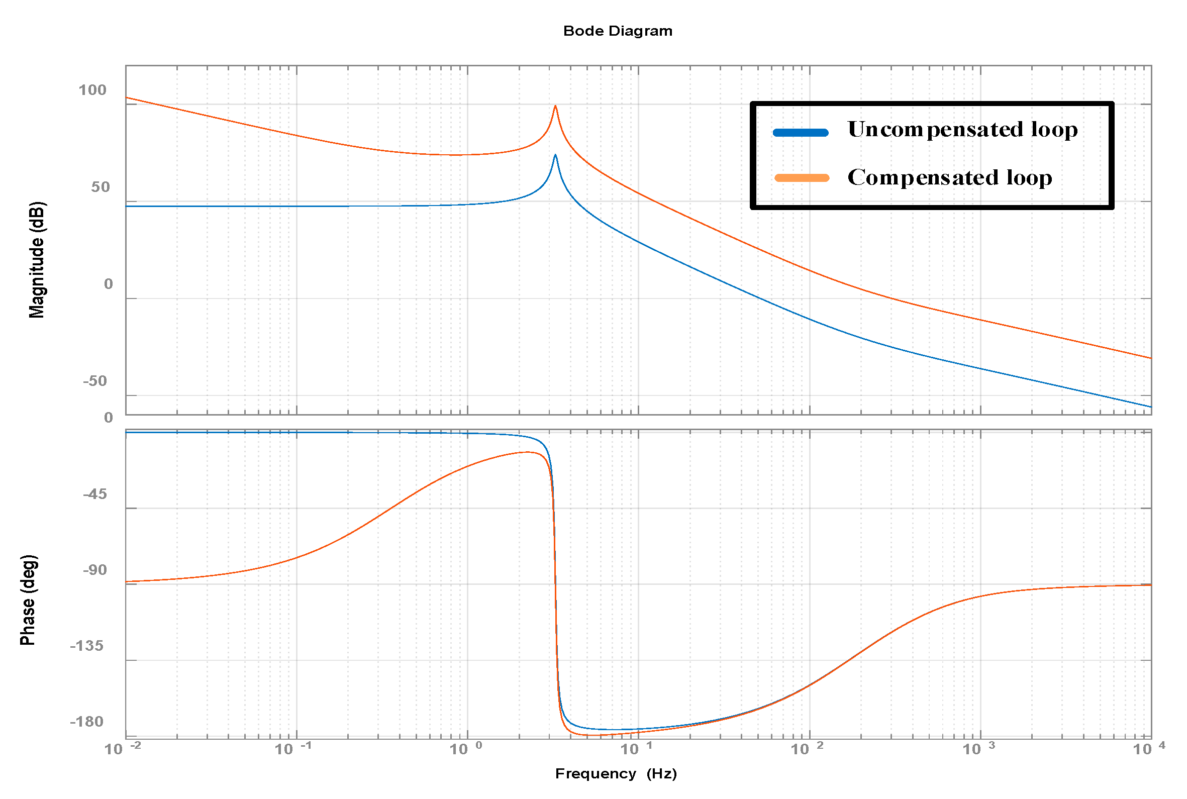
4. Design of Current Control Loop

This section describes the design of the current control loop in each module, as shown in Figure 6. The parameters of the current control loop are shown in Table 1. The design is implemented considering the parasitic resistance of the inductor. The current sensor gain and peak value of the carrier waveform are set to 1 by scaling.
Based on Figure 5, the transfer function of control to output current is expressed as:
G i d 1 = i ^ o u t 1 d ^ 1 = V i n 1 N 1 × L f 1 s + R L + A L f 1 s 2 + 2 R L L f 1 s + 2 A L f 1 s + 2 A R L + R L 2
A = R o R o C s + 1
The individual transfer functions of control to output current in each module are the same. In order to design an uncompensated loop, PI control is chosen. PI control, Gc1, is used from (12). In order to design current control loops, the open loop transfer is used:
T i = G c 1 × G i d 1
Figure 8 shows a bode plot of an open loop for the current control loop. The design is implemented using MATLAB. In Figure 8, the compensated current loop has a phase margin of 80.8° at 303 Hz. In this simulation, kp is 15 and ki is 40. The designed current control loop is stable can be seen in Figure 8.
The parameters of the two full-bridge DC–DC converters in an ISOP converter are the same as for the design of the controller. Since the parameters of module #1 and module #2 are set almost equally in the control loop, the PI control gain of each module is designed to be equal.

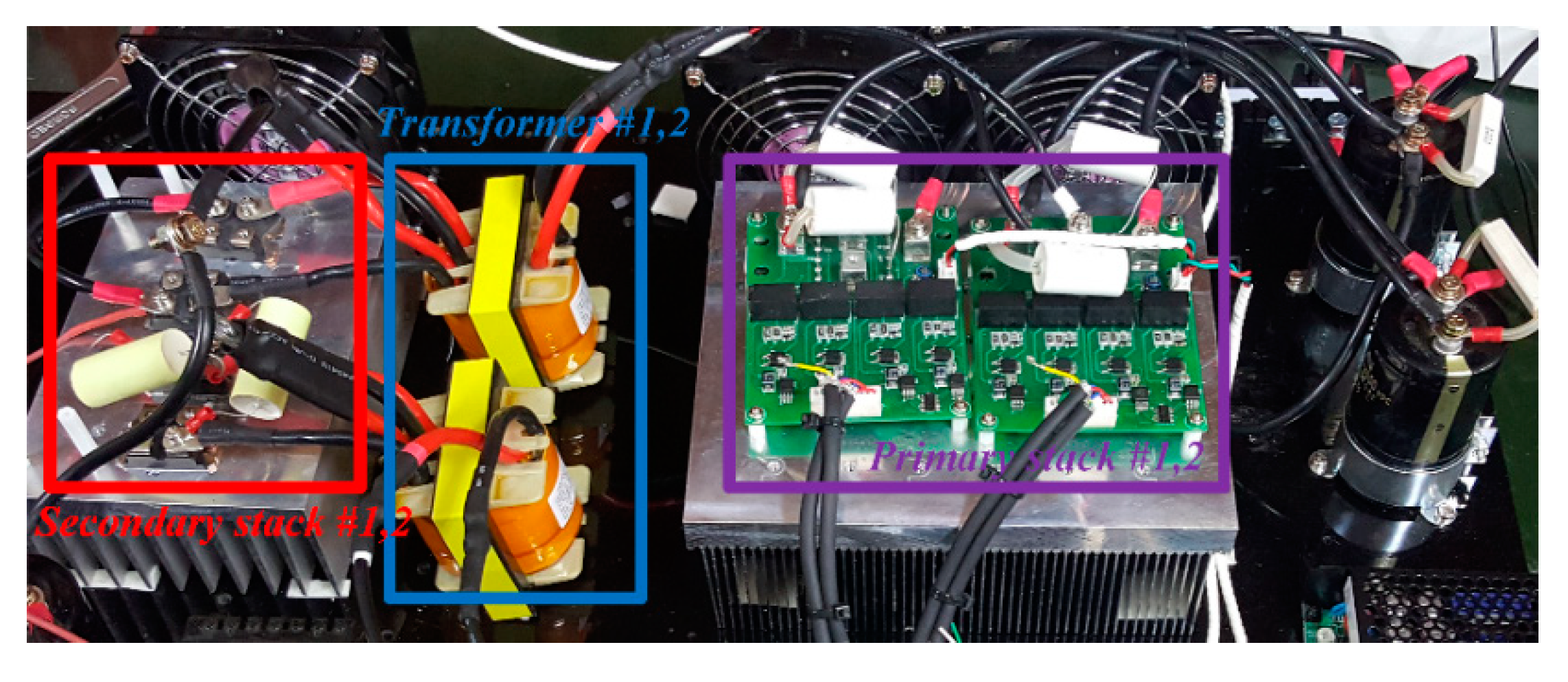
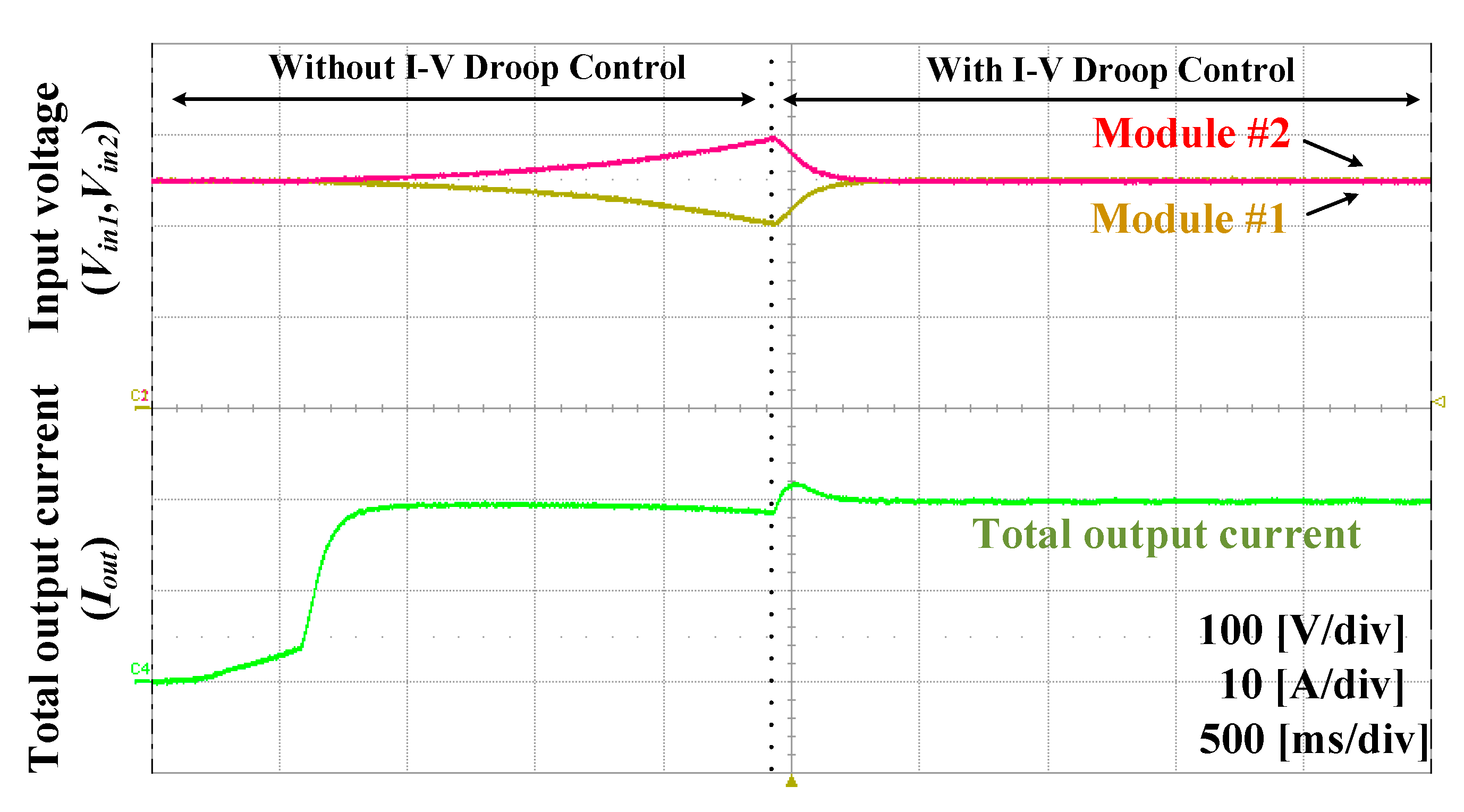
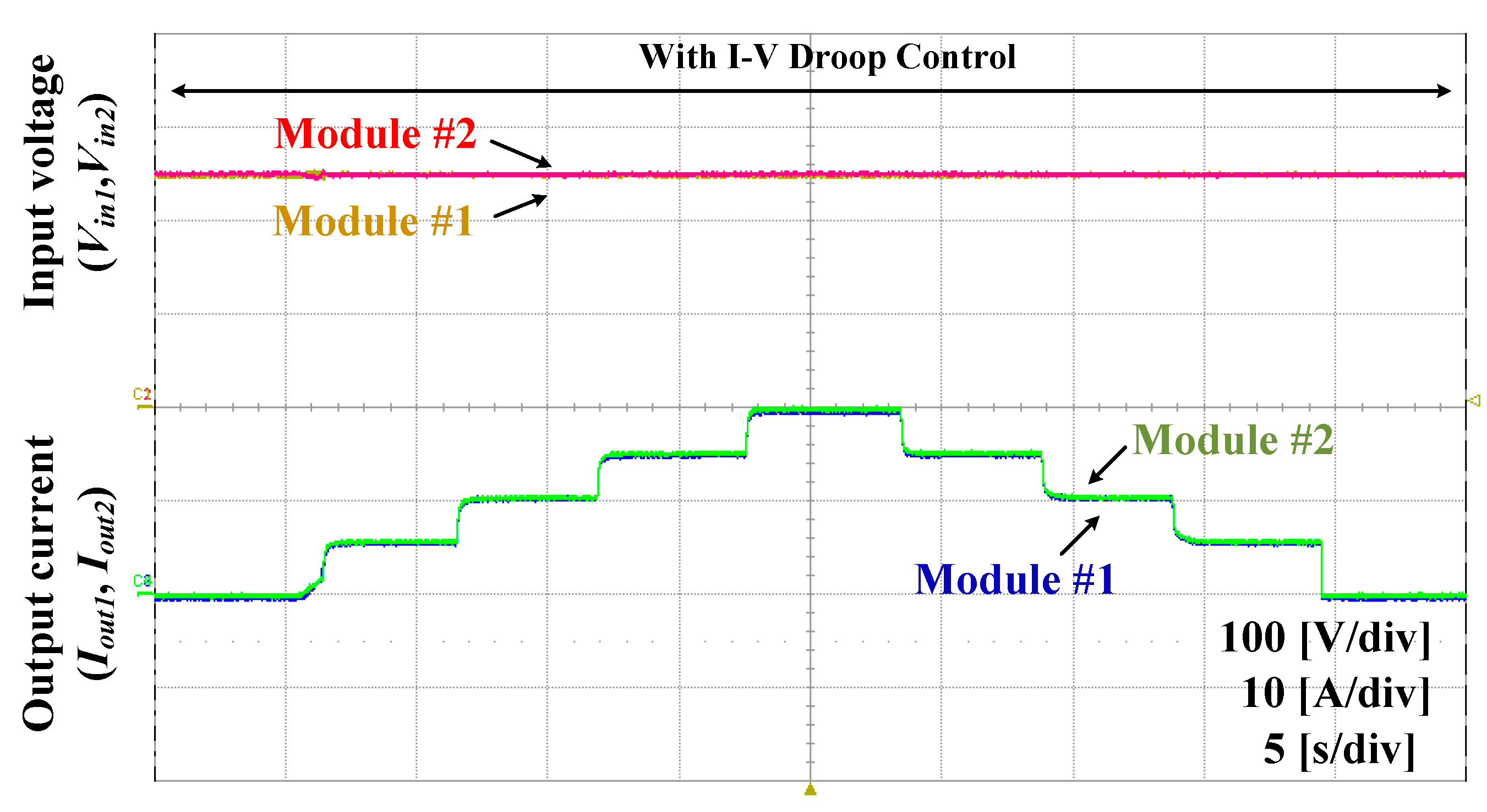
5. Experimental Result

In this section, the experimental results with decentralized control are shown. An ISOP converter consists of two modules, each with a full-bridge converter. Even if the individual PI gain are set equal in the previous section, the IVS and OCS cannot be implemented in an experiment because of a parameter mismatch in the ISOP converter, as shown in Table 2. The proposed control method is verified with a mismatched parameter. Other parameters are shown in Table 1.
To show the IVS and OCS performance of the proposed control method in a current control loop, the coefficient kdp is set to 0.35 and a 12 V battery is used for the load. The experiment is implemented using TMS320F28335. A photograph of the prototype is shown in Figure 9.
In the experimental results, the ISOP converter control decentralized the individual current control in this paper. First, the converter is tested only using individual current control, using current reference Iref* without the proposed control method. Later, the proposed control method is applied when the difference in the input voltages in the ISOP converter is 100 V. As a result, IVS and OCS is verified using the previous method in a steady state.
Figure 10 shows the experimental waveform of individual modules with the proposed control method. In Figure 10a, the input voltage deviation is increased because of parameter mismatch in an ISOP converter not using the proposed control method. The ISOP converter is controlled at 10 A output current. After the proposed control method is implemented, the individual output current reference is changed by the control characteristics. The output current of module #1 is decreased and the output current of module #2 is increased in a transient state. As a result, the IVS and OCS are implemented in a steady state. Figure 10b–d show experimental waveform of the output current from 15 to 25 A. As the output current increases from 10 to 25 A, IVS and OCS are also implemented as shown in Figure 10.
Figure 11 shows experimental waveform from the individual primary voltage of the transformer and output current. IVS is implemented in the primary voltage of the transformer with the proposed control method. The individual primary voltage of the transformer is changed according to varying output current reference with control characteristics. In a steady state, the IVS and OCS are implemented with low fluctuation.
Figure 12 shows experimental waveform of the total output current. In a transient state, the total output current fluctuates under 2 A. After this transient state, the total output current is maintained at 20 A. In Figure 12, the low fluctuations under 2A are shown due to the limitations of the transient response in the PI control.
Figure 13 shows the experimental waveform of the individual and total output current. Total output current is controlled at 40 A. The mode is changed during operation to show transient response. During this transient response, the total output current shows low fluctuations under 2 A. On the other hand, the OCS of the ISOP converter with the proposed control is stable in a steady state.
Figure 14 shows the experimental waveform of the changed output current with the proposed control method. When the output current is changed, while using the proposed control method, the IVS and OCS are stable under these variable loads. The corresponding experimental waveform shows very low fluctuation during this changing load.
Experiments under varying loads are conducted to prove the proposed control method. Experimental results show the performance of IVS and OCS remains stable without communication.

6. Conclusions

This paper proposes a decentralized control method to control stable IVS and OCS for ISOP converters in current control loop. In the proposed control method, the individual output current is changed as the individual input voltage states. Therefore, the proposed control method can achieve IVS and OCS without the need for communication and additional control loops. Also, this paper described the operation principle. For an analysis of the proposed control method and control loop design, small signal modeling of an ISOP converter is performed. Based on this small signal model, the stability of IVS with the current control loop is verified by pole-zero maps and individual current control loops are designed. Before using the proposed control method in experimental results, IVS and OCS are not able to be implemented properly due to parameter mismatch. However, IVS and OCS are implemented using the proposed control method at a low transient state. The performance of the IVS and OCS are verified through experiments.

Author Contributions

S.-H.K. conceived and designed the experiments; S.-H.K. and B.-J.K. performed the experiments; S.-H.K. and J.-M.P. analyzed the data; S.-H.K. and B.-J.K. contributed analysis tools; S.-H.K. wrote the paper. C.-Y.W. participated in research plan development and revised the manuscript. All authors have contributed to the manuscript. All authors have read and agreed to the published version of the manuscript.

Funding

This research was funded by National Research Foundation of Korea (No. 2019R1A2C2007216).

Acknowledgments

This work was supported by the National Research Foundation of Korea (NRF) grant funded by the Korea government (MSIP) (No. 2019R1A2C2007216).

Conflicts of Interest

The authors declare no conflict of interest.

References

  1. Lopez, M.; de Vicuna, L.G.; Castilla, M.; Gaya, P.; Lopez, O. Current distribution control design for paralleled DC/DC converters using sliding-mode control. IEEE Trans. Ind. Electron. 2004, 51, 419–428. [Google Scholar] [CrossRef]
  2. Perreault, D.J.; Selders, R.L.; Kassakian, J.G. Frequency-based current-sharing techniques for paralleled power converters. IEEE Trans. Power Electron. 1998, 13, 626–634. [Google Scholar] [CrossRef]
  3. Manias, S.N.; Kostakis, G. Modular DC–DC converter for high output voltage applications. Proc. Inst. Electr. Eng. 1993, 140, 97–102. [Google Scholar]
  4. Luo, S. A review of distributed power systems part I: DC distributed power system. IEEE Aerosp. Electron. Syst. Mag. 2005, 20, 5–16. [Google Scholar] [CrossRef]
  5. Chen, S.; Yang, S.; Cho, M. Analysis and implementation of an interleaved series input parallel output active clamp forward converter. IET Power Electron. 2013, 6, 774–782. [Google Scholar] [CrossRef]
  6. Chen, W.; Ruan, X.; Yan, H.; Tse, C.K. DC/DC Conversion Systems Consisting of Multiple Converter Modules: Stability, Control, and Experimental Verifications. IEEE Trans. Power Electron. 2009, 24, 1463–1474. [Google Scholar] [CrossRef]
  7. Huang, Y.; Tse, C.K.; Ruan, X. General Control Considerations for Input-Series Connected DC/DC Converters. IEEE Trans. Circuits Syst. I Regul. Pap. 2009, 56, 1286–1296. [Google Scholar] [CrossRef]
  8. Giri, R.; Choudhary, V.; Ayyanar, R.; Mohan, N. Common-duty-ratio control of input-series connected modular DC-DC converters with active input voltage and load-current sharing. IEEE Trans. Ind. Appl. 2006, 42, 1101–1111. [Google Scholar] [CrossRef]
  9. Shi, J.; Luo, J.; He, X. Common-Duty-Ratio Control of Input-Series Output-Parallel Connected Phase-shift Full-Bridge DC–DC Converter Modules. IEEE Trans. Power Electron. 2011, 26, 3318–3329. [Google Scholar] [CrossRef]
  10. Kimball, J.W.; Mossoba, J.T.; Krein, P.T. A Stabilizing, High-Performance Controller for Input Series-Output Parallel Converters. IEEE Trans. Power Electron. 2008, 23, 1416–1427. [Google Scholar] [CrossRef]
  11. Abrehdari, M.; Sarvi, M. Comprehensive sharing control strategy for input-series output-parallel connected modular DC–DC converters. IET Power Electron. 2019, 12, 3105–3117. [Google Scholar] [CrossRef]
  12. Ruan, X.; Chen, W.; Cheng, L.; Tse, C.K.; Yan, H.; Zhang, T. Control Strategy for Input-Series–Output-Parallel Converters. IEEE Trans. Ind. Electron. 2009, 56, 1174–1185. [Google Scholar] [CrossRef]
  13. Ayyanar, R.; Giri, R.; Mohan, N. Active input-voltage and load-current sharing in input-series and output-parallel connected modular DC-DC converters using dynamic input-voltage reference scheme. IEEE Trans. Power Electron. 2004, 19, 1462–1473. [Google Scholar] [CrossRef]
  14. Kim, J.-W.; Yon, J.-S.; Cho, B.H. Modeling, control, and design of input-series-output-parallel-connected converter for high-speed-train power system. IEEE Trans. Ind. Electron. 2001, 48, 536–544. [Google Scholar]
  15. Grbovic, P.J. Master/Slave Control of Input-Series- and Output-Parallel-Connected Converters: Concept for Low-Cost High-Voltage Auxiliary Power Supplies. IEEE Trans. Power Electron. 2009, 24, 316–328. [Google Scholar] [CrossRef]
  16. Chen, W.; Fu, X.; Xue, C.; Ye, H.; Syed, W.A.; Shu, L.; Ning, G. Indirect Input-Series Output-Parallel DC–DC Full Bridge Converter System Based on Asymmetric Pulsewidth Modulation Control Strategy. IEEE Trans. Power Electron. 2019, 34, 3164–3177. [Google Scholar] [CrossRef]
  17. Sha, D.; Guo, Z.; Liao, X. Cross-Feedback Output-Current-Sharing Control for Input-Series-Output-Parallel Modular DC–DC Converters. IEEE Trans. Power Electron. 2010, 25, 2762–2771. [Google Scholar] [CrossRef]
  18. Sha, D.; Deng, K.; Liao, X. Duty Cycle Exchanging Control for Input-Series-Output-Series Connected Two PS-FB DC-DC Converters. IEEE Trans. Power Electron. 2012, 27, 1490–1501. [Google Scholar] [CrossRef]
  19. Zumel, P.; Ortega, L.; Lázaro, A.; Fernández, C.; Barrado, A.; Rodrígue, A.; Hernando, M.M. Modular Dual-Active Bridge Converter Architecture. IEEE Trans. Ind. Appl. 2016, 52, 2444–2455. [Google Scholar] [CrossRef]
  20. Qu, L.; Zhang, D.; Zhang, B. Input Voltage Sharing Control Scheme for Input Series and Output Parallel Connected DC–DC Converters Based on Peak Current Control. IEEE Trans. Ind. Electron. 2019, 66, 429–439. [Google Scholar] [CrossRef]
  21. Qu, L.; Zhang, D.; Bao, Z. Output Current-Differential Control Scheme for Input-Series–Output-Parallel-Connected Modular DC–DC Converters. IEEE Trans. Power Electron. 2017, 32, 5699–5711. [Google Scholar] [CrossRef]
  22. Chen, W.; Wang, G.; Ruan, X.; Jiang, W.; Gu, W. Wireless Input-Voltage-Sharing Control Strategy for Input-Series Output-Parallel (ISOP) System Based on Positive Output-Voltage Gradient Method. IEEE Trans. Ind. Electron. 2014, 61, 6022–6030. [Google Scholar] [CrossRef]
  23. Xu, G.; Sha, D.; Liao, X. Decentralized Inverse-Droop Control for Input-Series–Output-Parallel DC–DC Converters. IEEE Trans. Power Electron. 2015, 30, 4621–4625. [Google Scholar] [CrossRef]
Figure 1. Simplified configuration of Input-Series-Output-Parallel (ISOP) converter.
Energies 13 01114 g001
Figure 2. Operation principle of decentralized control method. (a) Individual input voltage of ISOP converter; (b) Individual output current of ISOP converter.
Energies 13 01114 g002
Figure 3. Decentralized control characteristics.
Energies 13 01114 g003
Figure 4. Configuration of ISOP converter.
Energies 13 01114 g004
Figure 5. Small signal equivalent circuit model of ISOP converter.
Energies 13 01114 g005
Figure 6. The proposed decentralized control block diagrams of ISOP converter.
Energies 13 01114 g006
Figure 7. Simulation results of characteristic polynomial. (a) The pole-zero map of characteristic polynomial according to kp; (b) pole-zero map of characteristic polynomial according to ki; (c) pole-zero map of characteristic polynomial according to kdp.
Energies 13 01114 g007
Figure 8. Bode plots of open loop for current control loop.
Energies 13 01114 g008
Figure 9. Photograph of the prototype.
Energies 13 01114 g009
Figure 10. Experimental waveforms with proposed control method. (a) The individual input voltages and output current at 10 A; (b) individual input voltages and output current at 15 A; (c) individual input voltages and output current at 20 A; (d) individual input voltages and output current at 25 A.
Energies 13 01114 g010aEnergies 13 01114 g010b
Figure 11. Experimental waveform from Individual primary voltage of transformer and output current.
Energies 13 01114 g011
Figure 12. Experimental waveforms of total output current and individual input voltage.
Energies 13 01114 g012
Figure 13. Experimental waveform of the individual and total output current.
Energies 13 01114 g013
Figure 14. Experimental waveform of changed output current with proposed control method.
Energies 13 01114 g014
Table 1. Parameters of ISOP converter in simulation.
ParameterValue
Input voltage [V]500 [V]
Maximum output current #1 [A]30 [A]
Maximum output current #2 [A]30 [A]
Total output current [A]60 [A]
Output voltage [V]12 [V]
Input capacitor #1 [μF]500 [μF]
Input capacitor #2 [μF]500 [μF]
Output capacitor [μF]1000 [μF]
Turn ratio10:1
Switching frequency [kHz]20 [kHz]
Table 2. Mismatched parameters of ISOP converter.
ParameterValue
Leakage inductance of transformer #1 [μH]22 [μH]
Leakage inductance of transformer #2 [μH]17 [μH]
Output filter inductance #1 [μH]523 [μH]
Output filter inductance #2 [μH]505 [μH]

