Abstract
Microelectromechanical system (MEMS)-based piezoelectric energy harvesting (PEH) devices can convert the mechanical vibrations of their surrounding environment into electrical energy for low-power sensors. This electrical energy is amplified when the operation resonant frequency of the PEH device matches with the vibration frequency of its surrounding environment. We present the electromechanical modeling of two MEMS-based PEH devices to transform the mechanical vibrations of domestic washing machines into electrical energy. These devices have resonant structures with a T shape, which are formed by an array of multilayer beams and a ultraviolet (UV)-resin seismic mass. The first layer is a substrate of polyethylene terephthalate (PET), the second and fourth layers are Al and Pt electrodes, and the third layer is piezoelectric material. Two different types of piezoelectric materials (ZnO and PZT-5A) are considered in the designs of PEH devices. The mechanical behavior of each PEH device is obtained using analytical models based on the Rayleigh–Ritz and Macaulay methods, as well as the Euler–Bernoulli beam theory. In addition, finite element method (FEM) models are developed to predict the electromechanical response of the PEH devices. The results of the mechanical behavior of these devices obtained with the analytical models agree well with those of the FEM models. The PEH devices of ZnO and PZT-5A can generate up to 1.97 and 1.35 µW with voltages of 545.32 and 45.10 mV, and load resistances of 151.12 and 1.5 kΩ, respectively. These PEH devices could supply power to internet of things (IoT) sensors of domestic washing machines.
1. Introduction
In future smart cities, most domestic devices will be connected to internet of things (IoT) to improve their performance and communication with users and other devices. IoT can include everyday objects, such as laptops, mobile phones, washing machines, air conditioners, wearable devices, refrigerators, and other electronic devices [1,2,3,4]. IoT will allow a network between these devices for their remote distance control. To supply these devices, the mechanical vibrations of the surrounding environment could be used to generate electrical energy through energy harvesting (EH) devices. These devices can convert different energy types (e.g., heat, vibrations, and electromagnetic waves) into electrical energy. Thus, PEH devices could substitute the conventional batteries based on lithium.
Several researchers [5,6,7,8,9,10,11,12,13,14] have studied the piezoelectric effect of different materials to generate electrical energy. To take advantage of this piezoelectric effect, microelectromechanical system (MEMS)-based piezoelectric energy harvesting (PEH) devices could transform the mechanical vibrations of domestic washing machines into electrical energy. This energy can be obtained due to electric polarization of piezoelectric materials when they are exposed to mechanical deformations [15]. These piezoelectric materials can be deposited on cantilever structures. The PEH devices have emerged in recent years due to the possibility of integration with MEMS [16,17,18]. For instance, several researchers have developed MEMS-based PEH devices for different applications [19,20,21,22]. Lu et al. [23] reported a numerical modeling of a PEH cantilever for MEMS applications. They included the mechanical–electrical coupling effects in their conversion energy model; however, this model was only used for a simple cantilever. Mouapi et al. [24] studied the vibration spectrum of the Montreal subway network and adapted a piezoelectric transducer to these vibrations (11.5 Hz). In addition, they optimized the performance of a piezoelectric transducer, obtaining a voltage and output power of 4.5 V and 130 µwatts, respectively. They employed a device manufactured by Mide Technology® (Mide Technology Corporation, Medford, USA) and elaborated the transducer modeling using an electrical model. Pradeesh et al. [25] reported a PEH cantilever composed of Al and PZT-5A, which can generate an output voltage of 23.05 V at 93.7 Hz. These researchers studied the effect of the position of the piezoelectric material and proof mass along the cantilever using multiple computational simulations. Nevertheless, most studies about the mechanical behavior of MEMS-based PEH devices only consider mathematical and numerical simulations for simple cantilevers. For MEMS-based PEH devices formed by complex structures, mathematical models that can predict their mechanical behavior are required. In this work, we developed an analytical model to predict the mechanical behavior of two MEMS-based PEH devices that are composed of resonant structures with a T shape. These structures consider an array of multilayer beams and a UV-resin seismic mass. These beams include piezoelectric material on a substrate of PET. In the device design, two different types of piezoelectric materials (ZnO and PZT-5A) were employed. For the proposed analytical model, we used the Rayleigh–Ritz and Macaulay methods, as well as the Euler–Bernoulli beam theory. Furthermore, finite element method (FEM) models were obtained to estimate the electromechanical response of the PEH devices. The response of the mechanical performance of both PEH devices using the analytical models agrees well with those of the FEM models. For load resistances of 151.12 and 1.5 kΩ, PEH devices of ZnO and PZT-5A can generate up to 1.97 and 1.35 µW with voltages of 545.32 and 45.10 mV, respectively. Based on these results, PEH devices could supply power to IoT sensors of domestic washing machines.
This paper contains a second section that includes the electromechanical modeling of two PEH devices formed by ZnO and PZT-5A layers. The mechanical modeling of the devices was obtained using analytical and FEM models. Moreover, the electromechanical modeling of both devices was estimated through FEM models. Section 3 describes the results and discussion of the electromechanical behavior of the PEH devices. Finally, conclusions and future work are discussed in the fourth section.
2. Electromechanical Modeling
This section presents the electromechanical modeling of MEMS-based PEH devices considering designs with different piezoelectric layers (ZnO and PZT-5A) on a polyethylene terephthalate (PET) substrate.
Two MEMS-based PEH devices were designed to convert the mechanical vibrations of domestic washing machines into electrical energy. In these designs, we considered typical domestic washing machines with an operating frequency of 109 Hz [26]. Figure 1 shows the design for both PEH devices, which are formed by a resonant structure with a T shape. This structure contains an array of multilayer beams and a UV-resin seismic mass. This seismic mass was selected due to its good adhesion and homogeneity, and easy fabrication. The first design considers a PET substrate (150 µm thickness), ZnO layer (1.5 µm thickness), and a UV-resin proof mass (810 µm thickness). The second design has a PET substrate (150 µm thickness), PZT-5A layer (1.5 µm thickness), and a UV-resin proof mass (600 µm thickness). For both designs, thin (100 nm thickness) Al and Pt layers are used as the bottom and upper electrodes of the piezoelectric layer, which could extract the electrical current. In the analytical modeling of these PEH devices, the two electrodes are negligibe due to their thin thickness in comparison with the thickness of the other layers.
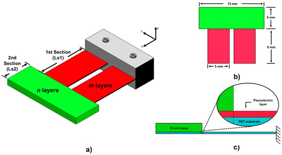
Figure 1.
Design of microelectromechanical system (MEMS)-based piezoelectric energy harvesting (PEH) devices with a T-shaped structure (a), isometric (b) top and (c) side view of the device.
The Rayleight–Ritz energy conservation model can be used to obtain the first bending frequency of a single clamped beam [27]. The maximum potential and kinetic energies of this model are given by [28]:
where y(x) is the deflection of the beam, E is the Young’s modulus of the beam material, L is the beam length, I(x) and A(x) are the bending moment and cross-section area of the beam, f is the bending resonant frequency of the beam, and ρ is the beam density.
Applying the energy conservation law (Pmax = Kmax) and solving for the first bending resonant frequency (f) of a single clamped beam, we obtain:
Next, the Rayleigh–Ritz method was adapted to obtain the first bending resonant frequency of the PEH devices with a T-shaped structure. For this, we considered a multilayer model with a variable cross-section in the yz plane (see Figure 2) with homogenous and isotropic materials. The geometries of the PEH devices are symmetric with the plane xy. The two electrodes of the PEH devices are negligible due to their thin thickness (100 nm) in comparison with the substrate PET and piezoelectric layer. In addition, the residual stress of the layers is negligible. Thus, the maximum potential, Pmax-multilayer, and kinetic, Kmax-multilayer, energies (two sections (S1 and S2), two layers for the first section (m = 2) and three layers for the second section (n = 3)) are determined by:
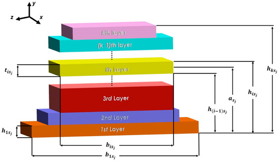
Figure 2.
Schematic view of a cross-section of the i-th layer on the j-th section of the MEMS-based PEH devices.
Applying the energy conservation law for the multilayer cross-section model (Pmax-multilayer = Kmax-multilayer), we obtained the first resonant bending frequency of the PEH devices:
The bending stiffness (EIz)sj in the j-th section of the PEH devices can be obtained by [29,30]:
The elastic centroid (asj) of each PEH device, in the j-th section, was assumed to be on the xz axis and is defined as [30]:
where tisj = hisj − h(i−1)sj is the i-th layer thickness in the j-th section, sj is the j-th section, k is the number of layers on the two different sections (k = m,n,…), Asj is the area on the j-th section, Eisj is the Young’s modulus of the i-th layer on the j-th section, ysj is the height of the j-th section, h(i−1)sj is the distance from the inferior plane of the first layer to the superior plane of the (i−1)th layer on the j-th section, bisj is the total width of the i-th layer ( bis1 includes the sum of width for each one of the two layers of same material at the same distance), and h0sj = 0.
The deflections, ysj, for both sections of the device structures were obtained by applying the Euler–Bernoulli theory and the Macaulay method as [31,32]:
where Msj(x) is the bending moment of the j-th section of each PEH device.
The solution of Equations (10) and (11) must consider the boundary conditions of the two sections of each PEH device. Equations (12) and (13) show the boundary conditions for the first and second section of the PEH devices, respectively:
To solve Equations (10) and (11), the bending moment functions of the PEH devices are required. This function is determined through the load function, q(x), of the PEH devices, which is obtained using the Macaulay method:
where the reaction load (R0) and the bending moment (M0) in the fixed support and the linear weight (wsj) of the j-th section of the devices are determined as (see Figure 3):
where g is the Earth’s gravity.
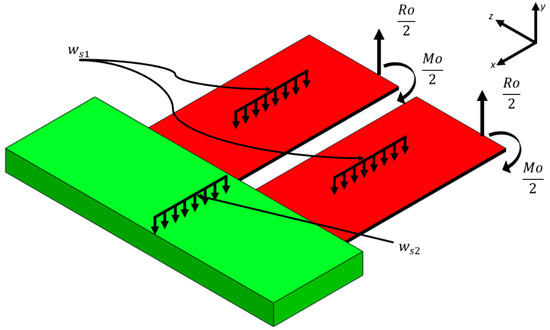
Figure 3.
Schematic view of the loads applied on the surface of the PEH devices.
The shear stress function, V(x), Equation (18), is obtained by integrating the load function, q(x), with respect to x, considering the integration rules of the Macaulay’s functions [32]. Next, the bending moment function, M(x), is determined by integrating the shear stress function, V(x), with respect to x:
The integration constants (C1 = 0 and C2 = 0) were calculated using the boundary conditions, in which the shear stress V(0) = R0 and bending moment M(0) = M0.
Thus, the bending moment function, M(x), is expressed as:
The bending moment function for each section of both PEH devices was determined through the Equation (20). The bending moment function for the first section, x ϵ (0,Ls1), and for the second section, x ϵ (Ls1,Ls12), are given by Equations (21) and (22), respectively:
The deflection, ysj, into each one of the devices’ sections was obtained by substituting the bending moment functions, Ms1 and Ms2, into the Equations (10) and (11), respectively, and using the integration rules of the Macaulay’s functions. Furthermore, the boundary conditions (Equations (12) and (13)) were applied to find these deflections:
Finally, the deflections of both PEH devices at resonance can be approximated using Qa times the static deflections () [27]:
where Qa is the quality factor of the PEH device due to air damping.
The potential and kinetic energies of the devices were estimated using Equations (23), (24), and (8). Next, the first bending resonant frequency of each device was estimated by substituting these energies into Equation (7). Table 1 shows the mechanical properties of the materials of the PEH devices. Table 2 depicts the geometrical parameters of both PEH devices based on the ZnO and PZT-5A layers. Table 3 illustrates the elastic centroid, bending moment, and linear weight for the two sections of both PEH devices.

Table 1.
Geometrical parameters and dimensions of the PEH devices.
Table 2.
Properties of the materials considered in both PEH devices. Reprint with permission from [33,34]. Copyright©2013, Scientific & Academic Publishing. Copyright©2012, Elsevier B.V.
Table 3.
Values of the parameters of both PEH devices obtained with the proposed analytical modeling.
Considering the proposed analytical modeling, the first bending resonant frequencies of the ZnO and PZT-5A-based PEH devices are 106.17 and 104.89 Hz, respectively.
In addition, the finite element method (FEM) models through software ANSYS® (ANSYS, Inc., Pittsburgh, USA) were developed to determine the electromechanical behavior of both MEMS-based PEH devices. First, the electromechanical modeling was applied to predict the modal and harmonic response of the PEH devices.
For the modal analysis of both PEH devices, FEM models were developed employing a mesh with hexahedral elements, with five divisions through all layers of each device (see Figure 4). By using a modal analysis, the first bending resonant frequencies are 108.84 and 108.54 Hz for the FEM models of the ZnO (Figure 5a) and PZT-5A (Figure 5b) PEH devices, respectively. Moreover, three more bending resonant frequencies of the FEM models for each PEH device were determined. Figure 6a,b depicts the second, third, and fourth resonant frequency of the FEM models.
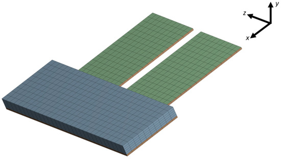
Figure 4.
View of the mesh used in finite element method (FEM) models of the PEH devices.
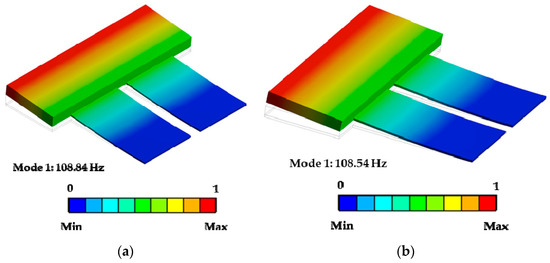
Figure 5.
First bending vibration mode with a normalized amplitude of the PEH devices of ZnO (a) and PZT-5A-based PEH devices (b).
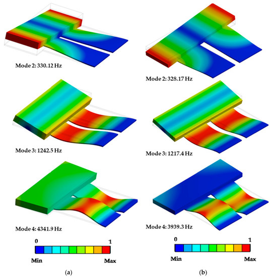
Figure 6.
Second, third, and fourth vibration mode with a normalized amplitude of PEH devices with ZnO (a) and PZT-5A layers (b) obtained using FEM models.
The first bending resonant frequency of the PEH devices with ZnO and PZT-5A layers obtained through the analytical model had relative errors of 2.45% and 3.36% compared with those of the FEM models.
For the harmonic analysis of the PEH devices, we used the following piezoelectric stress and piezoelectric dielectric matrices [33,34].
For the ZnO layer:
For the PZT-5A layer:
The Blom model was used to predict the quality factor (Qa) of the PEH devices due to the air damping. For this, the resonant structure of each device was approximated as a single clamped beam with a substrate (PET) and a proof mass at its end. This quality factor (Qa) was described as [35]:
where fr is first bending frequency, ρa and μ are the density and viscosity of the air, ρs is the PET substrate density, and b, h, and Le are the width, thickness, and length of each PEH substrate, respectively.
Considering Equations (28)–(30), PEH devices with ZnO and PZT-5A layers have quality factors at an atmospheric pressure of 265.18 and 263.52, respectively.
The damping ratio (ζ) and optimum load resistance (Ropt) of each PEH device can be determined by [27,36]:
where W and tp are the width and thickness of the piezoelectric layer, ε0 is the permittivity constant, and ε33 is the 3 × 3 element of the piezoelectric matrix.
3. Results and Discussion
This section reports the results and discussion of the electromechanical behavior of both MEMS-based PEH devices considering piezoelectric layers of ZnO and PZT-5A.
Figure 7a and b show the deflections at resonance of both PEH devices with ZnO and PZT-5A layers, which were obtained using the analytical and FEM models. The deflections calculated with the analytical modeling agree well with those of the FEM models. For the PEH devices with ZnO and PZT-5A layers, the relative errors of the analytical modeling are 5.38% and 5.33% in comparison with the FEM models. By using the analytical modeling, the maximum deflections of the ZnO and PZT-5A-based PEH devices achieve values up of 7.43 and 7.68 mm, respectively. On the other hand, the maximum deflections of both devices through FEM models are 7.83 and 8.09 mm, respectively.
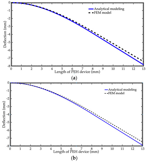
Figure 7.
Maximum displacements of the PEH devices at resonance with ZnO (a) and PZT-5A (b) layers.
The displacements of the PEH devices caused stresses and output voltages in the piezoelectric layers. The maximum normal stresses (x-axis) of the ZnO and PZT-5A layers are 38.45 and 11.74 MPa, respectively. These stresses do not overcome the tensile strengths (412 and 500 MPa) of the ZnO and PZT-5A layers, respectively [37,38]. Furthermore, these devices can operate with the same bending resonant frequency, with accelerations up to 5.2 and 21.33 m/s2 for ZnO and PZT-5A layers, respectively. These accelerations generate stresses that do not overcome the ZnO and PZT-5A tensile strengths.
The ZnO and PZT-5A-based PEH devices can generate maximum output voltages of 545.32 and 45.10 mV, respectively. Figure 8 shows the generated voltages as a function of the frequency.
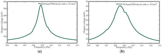
Figure 8.
Generated voltages as function of the frequency of the PEH devices with ZnO (a) and PZT-5A (b) layers.
The optimum load resistances (151.12 and 1.50 kΩ) reached by the ZnO and PZT-5A-based PEH devices were calculated using Equation (32). These load resistances were utilized to obtain the output power for both PEH devices. Thus, the output power is described as:
where is the output voltage.
The output power calculated for ZnO and PZT-5A-based PEH devices is 1.97 and 1.35 µW, respectively. Figure 9 depicts the output powers of the PEH devices with respect to their operation frequency using the FEM models. This output power can supply electrical energy to low-power electronic devices, such as pressure and temperature sensors [39]. The proposed PEH devices can operate at resonance with frequencies caused by vibration sources, such as domestic washing machines. Table 4 indicates the values of the main parameters of the PEH devices obtained through FEM models.
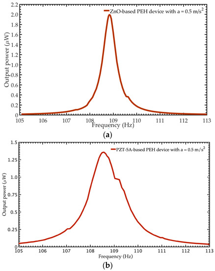
Figure 9.
Generated power with respect to the frequency of the PEH devices with ZnO (a) and PZT-5A (b) layers.
Table 4.
Results of the main parameters of the MEMS-based PEH devices obtained using the FEM models.
PEH devices could supply electrical energy to low-power IoT sensors that are exposed to mechanical vibrations to their surrounding environment. For instance, sensors used for monitoring the temperature, pressure, position, humidity, acceleration, and magnetic field. To obtain the maximum output voltage and power of PEH devices, the operation frequency of these devices must be similar to that of the mechanical vibrations’ source. An array of PEH devices can be used to increase the supplied power to IoT sensors. In our particular case, we designed two MEMS-based PEH devices to transform the vibrations of domestic washing machines into electrical energy. These devices could be installed in other vibration sources. For this, dimensions of the structure of PEH devices must be modified to achieve operation resonant frequencies approximately equal to those of the new vibration sources. Therefore, PEH devices could supply electrical energy to different types of sensors.
The operation resonant frequencies of the proposed PEH devices could be altered by changing the thickness of their seismic masses. The PEH devices must be designed to have maximum stresses less than the rupture stresses of their materials. In the FEM models, the thickness of the seismic mass was modified to obtain its effect on the first bending resonant frequency of both PEH devices, as shown in Figure 10a,b. Thus, the thickness of the seismic mass of both PEH devices could be adjusted to change their potential application.
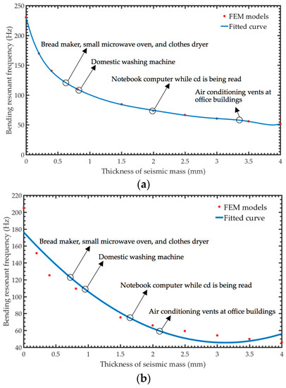
Figure 10.
Variation of the first bending resonant frequency of PEH devices with ZnO (a) and PZT-5A (b) layers due to the shift of the thickness of the seismic mass.
4. Conclusions
The electromechanical modeling of two MEMS-based PEH devices designs with layers of ZnO and PZT-5A was developed. These designs can perform at their first bending resonant frequency, with values close to those caused by the vibrations of domestic washing machines. The PEH devices were formed by an array of multilayer beams and a UV-resin seismic mass. These beams included a substrate of polyethylene terephthalate (PET) and two different types of piezoelectric layers (ZnO and PZT-5A). The mechanical behavior of the PEH devices was obtained using analytical models based on the Rayleigh–Ritz and Macaulay methods, as well as the Euler–Bernoulli beam theory. Furthermore, finite element method (FEM) models were generated to estimate the electromechanical behavior of both PEH devices. The results of the mechanical performance of these devices obtained with the analytical models agreed well with those of the FEM models. The PEH devices with ZnO and PZT-5A layers generated 1.97 and 1.35 µW with voltages of 545.32 and 45.10 mV, and load resistances of 151.12 and 1.5 kΩ, respectively. The output voltages of these PEH devices could be supplied to low-power IoT sensors incorporated into domestic washing machines.
Author Contributions
Analytical modeling of the PEH devices, E.M.-C.; reporting FEM models of the PEH devices, L.A.V.-M. and J.A.D.A.-A.; proposed methodology, L.A.A.-C. analyzed the results of the analytical and FEM models, C.A.C.-Á.; writing, A.L.H.-M. All authors have read and agreed to the published version of the manuscript.
Funding
This research was funded by project PFCE 2019 “DES Técnica Veracruz” through grant 30MSU0940B-21.
Acknowledgments
E. Martínez-Cisneros, J. A. Del Angel-Arroyo and L. Velosa-Moncada thank CONACYT by the scholarship received during their master and doctoral studies.
Conflicts of Interest
The authors declare no conflict of interest
References
- Narita, F.; Fox, M. A review on piezoelectric, magnetostrictive, and magnetoelectric materials and device technologies for energy harvesting applications. Adv. Eng. Mater. 2019, 20, 1700743. [Google Scholar] [CrossRef]
- Setthawong, P.; Osothsilp, A.; Triyason, T. An IoT implementation for vacancy state of public coin operated washing machine using vibration level sensors in an apartment setting in Thailand. In Mobile and Wireless Technologies 2017. ICMWT 2017; Kim, K., Joukov, N., Eds.; Lecture Notes in Electrical Engineering; Springer: Singapore, 2017; Volume 425, pp. 129–138. [Google Scholar]
- Dange, S.; Chatterjee, M. IoT Botnet: The Largest Threat to the IoT Network. In Data Communication and Networks. Advances in Intelligent Systems and Computing; Jain, L., Tsihrintzis, G., Balas, V., Sharma, D., Eds.; Springer: Singapore, 2020; Volume 1049, pp. 137–157. [Google Scholar]
- Malik, M.; Dutta, M.; Granjal, J. A Survey of Key Bootstrapping Protocols Based on Public Key Cryptography in the Internet of Things. IEEE Access 2019, 7, 27443–27464. [Google Scholar] [CrossRef]
- Wang, Z.L.; Song, J. Piezoelectric Nanogenerators Based on Zinc Oxide Nanowire Arrays. Science 2006, 312, 242–246. [Google Scholar] [CrossRef] [PubMed]
- Hu, D.; Yao, M.; Fan, Y.; Ma, C.; Fan, M.; Liu, M. Strategies to achieve high performance piezoelectric nanogenerators. Nano Energy 2019, 55, 288–304. [Google Scholar] [CrossRef]
- Yuan, H.; Lei, T.; Qin, Y.; Yang, R. Flexible electronic skins based on piezoelectric nanogenerators and piezotronics. Nano Energy 2019, 59, 84–90. [Google Scholar] [CrossRef]
- Yan, J.; Liu, M.; Jeong, Y.G.; Kang, W.; Li, L.; Zhao, Y.; Deng, N.; Cheng, B.; Yang, G. Performance enhancements in poly(vinylidene fluoride)-based piezoelectric nanogenerators for efficient energy harvesting. Nano Energy 2019, 56, 662–692. [Google Scholar] [CrossRef]
- Maiwa, H. Piezoelectric Energy Harvesting. In Piezoelectric Materials; Ogawa, T., Ed.; Intech: Rijeka, Croatia, 2016; pp. 129–142. [Google Scholar]
- Szperlich, P.; Toroń, B. An Ultrasonic Fabrication Method for Epoxy Resin/SbSI Nanowire Composites, and their Application in Nanosensors and Nanogenerators. Polymers 2019, 11, 479. [Google Scholar] [CrossRef]
- Nowak, M.; Tański, T.; Szperlich, P.; Matysiak, W.; Kępińska, M.; Stróż, D.; Bober, Ł.; Toroń, B. Using of sonochemically prepared SbSI for electrospun nanofibers. Ultrason. Sonochem. 2017, 38, 544–552. [Google Scholar] [CrossRef]
- Toroń, B.; Szperlich, P.; Nowak, M.; Stróż, D.; Rzychoń, T. Novel piezoelectric paper based on SbSI nanowires. Cellulose 2018, 25, 7–15. [Google Scholar] [CrossRef]
- Purusothaman, Y.; Rao Alluri, N.; Chandrasekhar, A.; Kim, S.-J. Photoactive piezoelectric energy harvester driven by antimony sulfoiodide (SbSI): A AVBVICVII class ferroelectric-semiconductor compound. Nano Energy 2018, 50, 256–265. [Google Scholar] [CrossRef]
- Jesionek, M.; Toroń, B.; Szperlich, P.; Biniaś, W.; Biniaś, D.; Rabiej, S.; Starczewska, A.; Nowak, M.; Kępińska, M.; Dec, J. Fabrication of a new PVDF/SbSI nanowire composite for smart wearable textile. Polymer 2019, 180, 121729. [Google Scholar] [CrossRef]
- Manbachi, A.; Cobbold, R.S. Development and application of piezoelectric materials for ultrasound generation and detection. Ultrasound 2011, 19, 187–196. [Google Scholar] [CrossRef]
- Chamanian, S.; Muhtaroğlu, A.; Külah, H. A Self-Adapting Synchronized-Switch Interface Circuit for Piezoelectric Energy Harvesters. IEEE Trans. Power Electron. 2020, 35, 901–912. [Google Scholar] [CrossRef]
- Chauhan, S.S.; Joglekar, M.M.; Manhas, S.K. High Power Density CMOS Compatible Micro-Machined MEMs Energy Harvester. IEEE Sens. J. 2019, 19, 9122–9130. [Google Scholar] [CrossRef]
- Chamanian, S.; Uluşan, H.; Koyuncuoğlu, A.; Muhtaroğlu, A.; Külah, H. An Adaptable Interface Circuit With Multistage Energy Extraction for Low-Power Piezoelectric Energy Harvesting MEMS. IEEE Trans. Power Electron. 2019, 34, 2739–2747. [Google Scholar] [CrossRef]
- Li, G.; Yi, Z.; Hu, Y.; Liu, J.; Yang, B. High-performance low-frequency MEMS energy harvester via partially covering PZT thick film. J. Micromechan. Microeng. 2018, 28, 095007. [Google Scholar] [CrossRef]
- Tian, W.; Ling, Z.; Yu, W.; Shi, J. A Review of MEMS Scale Piezoelectric Energy Harvester. Appl. Sci. 2018, 8, 645. [Google Scholar] [CrossRef]
- Damya, A.; Abbaspour Sani, E.; Rezazadeh, G. An innovative piezoelectric energy harvester using clamped–clamped beam with proof mass for WSN applications. Microsyst. Technol. 2018, (in press). [CrossRef]
- Liu, H.; Lee, C.; Kobayashi, T.; Tay, C.J.; Quan, C. Investigation of a MEMS piezoelectric energy harvester system with a frequency-widened-bandwidth mechanism introduced by mechanical stoppers. Smart Mater. Struct. 2012, 21, 035005. [Google Scholar] [CrossRef]
- Lu, F.; Lee, H.P.; Lim, S.P. Modeling and analysis of micro piezoelectric power generators for micro-electromechanical-systems applications. Smart Mater. Struct. 2003, 13, 57. [Google Scholar] [CrossRef]
- Mouapi, A. Design, Modeling and Simulation of Piezoelectric Microgenerator for application in Underground Vehicles. In 2019 IEEE International Conference on Environment and Electrical Engineering and 2019, IEEE Industrial and Commercial Power Systems Europe (EEEIC/I & CPS Europe), 11–14 June 2019; IEEE: Genova, Italy, June 2019; pp. 1–5. [Google Scholar]
- Pradeesh, E.L.; Udhayakumar, S. Effect of placement of piezoelectric material and proof mass on the performance of piezoelectric energy harvester. Mech. Syst. Signal Process. 2019, 130, 664–676. [Google Scholar] [CrossRef]
- Roundy, S.J. Energy Scavenging for Wireless Sensor Nodes with a Focus on Vibration to Electricity Conversion. Ph.D. Thesis, University of California, Berkeley, CA, USA, 2003. [Google Scholar]
- Rao, S.S. Mechanical Vibrations, 4th ed.; Pearson-Prentice Hall: Upper Saddle River, NJ, USA, 2004; pp. 134–633. [Google Scholar]
- Beer, F.P.; Johnston, E.R., Jr.; David, F.; Eisenberg, E.R. Vector Mechanics for Engineers: Statics and Dynamics, 10th ed.; McGraw Hill Higher Education: New York, NY, USA, 2012; p. 1280. [Google Scholar]
- Weaver, W., Jr.; Timoshenko, S.P.; Young, D.H. Vibration Problems in Engineering, 5th ed.; John Wiley & Sons: New York, USA, 1990; p. 624. [Google Scholar]
- Hibbeler, R.C. Engineering mechanics: Statics, 12th ed.; Pearson Education: Upper Saddle River, NJ, USA, 2010; p. 650. [Google Scholar]
- Bauchau, O.A.; Craig, J.I. Euler-Bernoulli beam theory. In Structural analysis; Bauchau, O.A., Craig, J.I., Eds.; Springer: Dordrecht, The Netherlands, 2009; pp. 173–221. [Google Scholar]
- Craig, R.R., Jr. Mechanics of Materials, 1st ed.; John Wiley & Sons Inc.: New York, NY, USA, 1996; pp. 243–250. [Google Scholar]
- Tung, V.T.; Tinh, N.T.; Yen, N.H.; Tuan, D.A. Evaluation of Electromechanical Coupling Factor for Piezoelectric Materials Using Finite Element Modeling. Int. J. Mater. Chem. 2013, 3, 4. [Google Scholar]
- Pan, C.T.; Liu, Z.H.; Chen, Y.C. Study of broad bandwidth vibrational energy harvesting system with optimum thickness of PET substrate. Curr. Appl. Phys. 2012, 12, 684–696. [Google Scholar] [CrossRef]
- Blom, F.R.; Bouwstra, S.; Elwenspoek, M.; Fluitman, J.H.J. Dependence of the quality factor of micromachined silicon beam resonators on pressure and geometry. J. Vacuum Sci. Technol. 1992, 10, 19–26. [Google Scholar] [CrossRef]
- Kuang, Y.; Daniels, A.; Zhu, M. A sandwiched piezoelectric transducer with flex end-caps for energy harvesting in large force environments. J. Phys. D Appl. Phys. 2017, 50, 345501. [Google Scholar] [CrossRef]
- Ong, C.W.; Zong, D.G.; Aravind, M.; Choy, C.L.; Lu, D.R. Tensile strength of zinc oxide films measured by a microbridge method. J. Mater. Res. 2003, 18, 2464–2472. [Google Scholar] [CrossRef]
- Cao, H.; Evans, A.G. Nonlinear deformation of ferroelectric ceramics. J. Am. Ceram. Soc. 1993, 76, 890–896. [Google Scholar] [CrossRef]
- Iqbal, M.; Khan, F.U. Hybrid vibration and wind energy harvesting using combined piezoelectric and electromagnetic conversion for bridge health monitoring applications. Energy Convers. Manag. 2018, 172, 611–618. [Google Scholar] [CrossRef]


© 2020 by the authors. Licensee MDPI, Basel, Switzerland. This article is an open access article distributed under the terms and conditions of the Creative Commons Attribution (CC BY) license (http://creativecommons.org/licenses/by/4.0/).