Fire Behavior of Electrical Installations in Buildings


Abstract
1. Introduction
- -
- Power supply installations
- -
- Telecommunication and information network
- -
- Intercom, antenna and alarm systems
- -
- Lightning protection systems
2. Evaluation of Electrical Installation under Fire Conditions
3. Research Problem
4. Experiments
4.1. Series A—Main Experiments of Electrical Installations by Means of SBI Apparatus
4.1.1. Single Burning Item (SBI) Experimental Apparatus
- -
- Test room with the inner dimensions 2.4 m (height) and 3 m × 3 m floor area. The walls were made of calcium silicate, non-combustible material of class A1 according to EN 13,501-1 [26],
- -
- the test apparatus (trolley, frame, burners, hood, collector and ducting),
- -
- the smoke exhaust system,
- -
- general measuring equipment [27].
- -
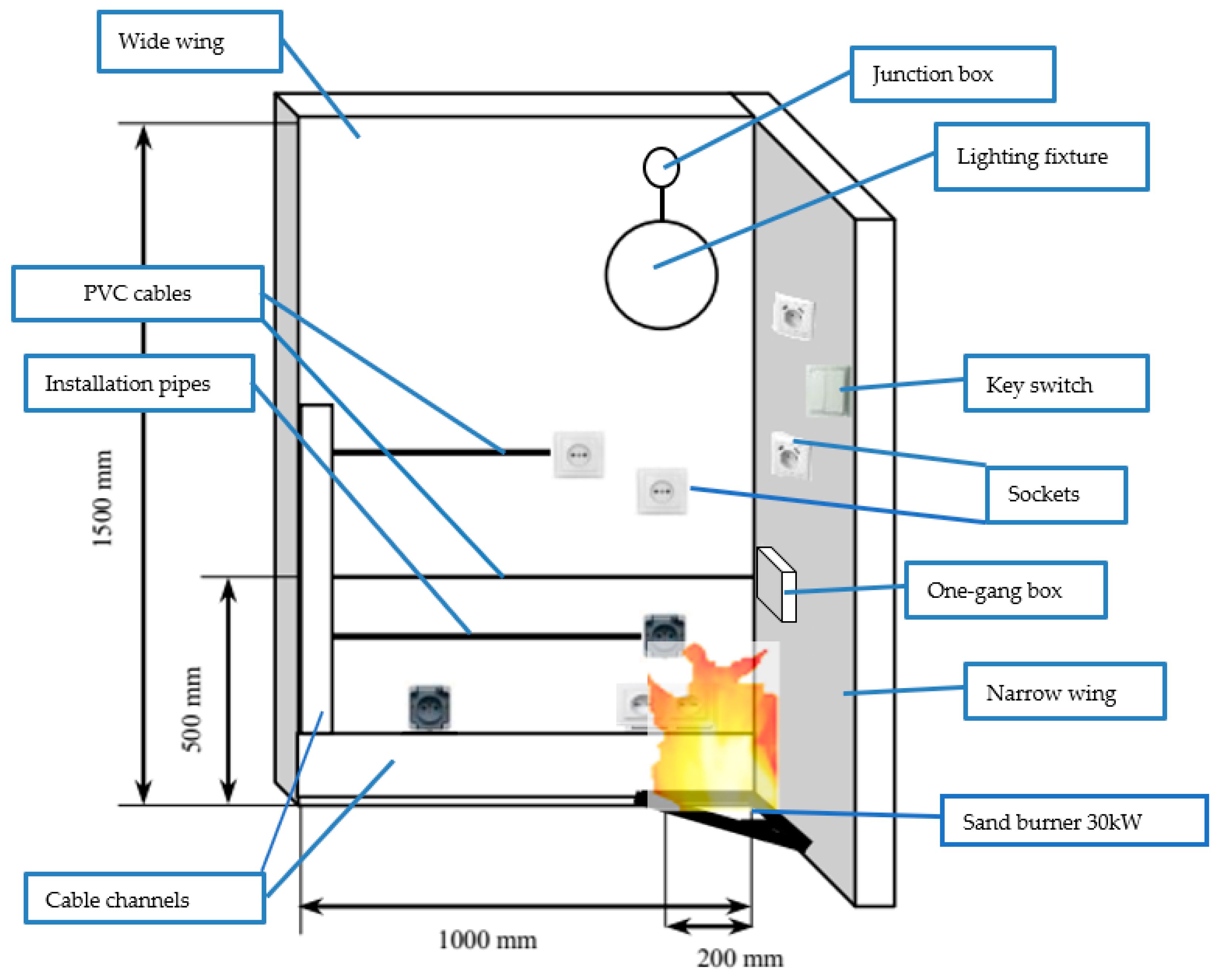
- A trolley, on which two perpendicular specimen parts were placed, with a sandbox burner at the bottom of the vertical corner,
- -
- a large wing (1.00 m × 1.50 m) and a small wing (0.49 m × 1.50 m), which were mounted in a left angle and create a corner (Figure 1),
- -
- a gas burner (Figure 1) with a heat release rate of 30 kW located in the corner during the testing (dimensions of 249 × 249 mm),
- -
- a hood, on top of the frame, which collected the combustion gases through a collector located on top of the hood with baffles and a horizontal outlet for the exhaust duct, which were (J-shaped), a circular tube with an inner diameter of 315 mm and insulated with 50 mm high-temperature resistant mineral wool [27].
4.1.2. Specimens
- -
- -
- -
- Specimen 3—wall made of combustible material (wood particleboard (oriented strand board, OSB) 15 mm in thickness) without mounted circuit electrical installation.
- -
- Specimen 4—wall made of non-combustible material (calcium-silicate board) without mounted circuit electrical installation.
4.1.3. Experimental Measurements and Visual Observations
- -
- heat generation: FIGRA0.2MJ, FIGRA0.4MJ, THR600s
- -
- smoke emission: SMOGRA, TSP600s
- -
- presence of burning droplets and particles
- -
- lateral flame spread (LFS)
Specimen 1
- -
- 120 s—the ignition of the main burner electrical circuit, which was surface-mounted in a polypropylene fluted pipe, began to burn, spreading the flame. Burning drops of polypropylene fell on the perimeter located below, made in a PVC pipe, igniting along its entire length. However, the fire spread progressed slowly along the PVC installation. Ignition points were topical, but smoke was visible.
- -
- 460 s—the lampshade of the lighting fixture cracked, which was located above the source of the fire.
- -
- 840 s—the entire polypropylene circuit was burned along with the wires’ insulation of this circuit. The fire reached the vertical circuit made in the PVC wall duct and ignited the circuit. The remaining circuits in the PVC channels were burning, but they did not quicken the spread of the fire. Faster than the shields where the wires were arranged, the fire spread on the wires.
- -
- 900 s—the insulation on the wires was completely burned. The enclosures of the plug sockets and lighting connectors melted over the fire but did not spread the flame. The burning electrical system caused a significant increase in temperature, as a result of which surfaces of the wall from the OSB board began to increasingly burn.
- -
- 940 s—the inner wall cladding burned. The fire got inside the wall and ignited the electrical circuits that were stacked inside. Then the outer lining of the wall caught fire. The wall insulation that was made of mineral wool did not ignite.
- -
- At that time, the electrical system practically ceased to exist (except copper wires of the cables). Only the wall itself on the surface of the whole specimen was on fire. After the fire source was extinguished, the walls and other components of the electrical system continued to burn.
- -
- 1500 s—completion of the experiment; internal wall cladding burned completely.
Specimen 2
- -
- 390 s—since the ignition of the burner began to melt the skirting channel, within the range of the ignition source, the insulation of the wires placed in this channel ignited.
- -
- 420 s—the second end of the channel began to generate smoke, but it was not the result of smoking (smoke did not appear), but rather was the result of the charring of the wall cladding.
- -
- 780 s—smoking stopped. The socket and connector housings did not burn. The circuits of the installation caught fire within the source of the fire but did not spread the flame. The wall cladding did not burn.
- -
- 1500 s—until the end of the experiment, the cover plates of the sockets and fittings did not spread the flame and did not burn; only the plastics from which they were made (PVC, melamine) plasticized at a high temperature. Equipment and accessories that were out of range of the source of the fire were not destroyed. The lighting fixture that was within the source of the fire was also not destroyed. After extinguishing the burner, the wall and electrical components did not propagate the flame.
- -
- The fire did not extend to the wall.
Specimen 3
- -
- 430 s—inner wall cladding began to burn within the range of the fire source.
- -
- 600 s—about 50% of the longer wall wing and about 75% of the shorter one were already burned. The board did not give off smoke.
- -
- 1100 s—internal board burned. The fire extended to the wall.
- -
- 1500 s—by the end of the experiment, the inner plate burned completely within the source of the fire.
Specimen 4
4.2. Series B—Complementary Semi-Real Scale Experiments of Electrical Cable Unconnected to the Mains
4.3. Series C—Complementary Experiments of Electrical Installations Connected to the Mains
- -
- cable channels—only circuit No. 1 (PVC)
- -
- electrical conduit rigid pipes on the exposed surface of the specimen (on the front walls) (PVC)
- -
- electrical conduit corrugated pipes between the substrate and backing board, on the rare surface (polypropylene)
- -
- installation without any pipes on the exposed surface of the specimen (on the front walls)
- -
- installation without any pipes on the rare surface between the substrate and backing board
- -
- junction box with a diameter of 60 mm—two items (polyethylene and polypropylene)
- -
- one-gang box with diameter of 60 mm—two items
- -
- unipolar key switch, 10 A, 250 V—one item (PVC, melamine)
- -
- single socket 10/16 A, 250 V—two items (PVC, melamine)
- -
- lighting fixture 100 W—one item (ceramic)
- -
- bulb E27 100 W—one item
- -
- coaxial electric power cable YDY 3 × 1.5 mm2—5 m (PVC)
- -
- coaxial electric power cable YDY 3 × 2.5 mm2—10 m (PVC)
- -
- coaxial electric power cable YDY 5 × 2.5 mm2—15 m (PVC)
- -
- wall switchgear with TH 35 rail, minimum width in modules 8 × 17.5 mm
- -
- unipolar circuit breaker (16 A, 230/400 V, characteristic C)
- -
- unipolar circuit breaker (10 A, 230/400 V, characteristic B)
- -
- four-pole residual current circuit breaker (40 A, 400 V, 30 mA)
- -
- under the uncovered surface of the socket-fixed without the bottom cover and without covering directly on the surface
- -
- under the surface-mounted plug socket shielded—having a bottom cover
5. Discussion and Conclusions
- -
- The presented preliminary results confirm that the SBI method is suitable for the evaluation of electrical installations in terms of the fire safety of buildings. PVC cable channels and installation pipes are usually made of combustible polymeric materials that also need to be fire tested by mean of the cone calorimeter test method. They constitute a significant element from the point of view of fire safety for buildings, consequently increasing the ability of fire spread over walls, ceiling and floorings.
- -
- Fire spread, heat release and smoke production parameters are the significant factors increasing the fire properties of electrical installations and thus the fire properties of entire buildings. A dense smoke rich in solid and liquid species makes evacuation from the fire difficult, and toxic gas fumes cause intoxication and fatality effects to fire victims. As it was shown in the previous studies of the authors [21], there is a significant impact of constructional and material parameters on the fire properties of electric cables. Thus, the replacement of PVC-based electrical cables with halogen-free cables can reduce the fire performance of entire electrical installations and consequently improve the fire safety of entire buildings.
Author Contributions
Funding
Acknowledgments
Conflicts of Interest
References
- IET. Wiring rules. J. Inst. Electr. Eng. 1907. [Google Scholar] [CrossRef]
- Bates, B. Safer electrical installations. IEE Rev. 1998, 44, 131–132. [Google Scholar] [CrossRef]
- McClung, L.B.; Hill, D.J. Electrical system design techniques to improve electrical safety. In Proceedings of the 2010 IEEE IAS Electrical Safety Workshop, ESW 2010, Memphis, TN, USA, 1–5 February 2010. [Google Scholar] [CrossRef]
- Tenaga, S.; TNB (Tenaga Nasional Berhad, Distribution Division). Guidelines for Electrical Wiring in Residential Buildings; TNB: Jalan Sultan Ismail, Kuala Lumpur, 2008. Available online: www.st.gov.my (accessed on 1 December 2020).
- Gentile, P.; Mazzaro, M.; Turturici, C. Fire safety criteria in electrical installations design. In Proceedings of the 2017 17th IEEE International Conference on Environment and Electrical Engineering and 2017 1st IEEE Industrial and Commercial Power Systems Europe, EEEIC/I and CPS Europe 2017, Milan, Italy, 6–9 June 2017. [Google Scholar] [CrossRef]
- BS 7671 Requirements for Electrical Installations. Electrical Safety and the Law; Blackwell Science Ltd.: Hoboken, NJ, USA, 2008; pp. 122–174. [Google Scholar] [CrossRef]
- Regulation (EU) No 305/2011 of the European Parliament and of the Council of 9 March 2011 Laying down Harmonized Conditions for the Marketing of Construction Products and Repealing Council Directive 89/106/EEC. Available online: https://eur-lex.europa.eu/legal-content/EN/TXT/?uri=celex%3A32011R0305 (accessed on 1 December 2020).
- Babrauskas, V. Research on electrical fires: The state of the art. Fire Saf. Sci. 2008, 3–18. [Google Scholar] [CrossRef]
- Barros, J.; Diego, R.I. A review of measurement and analysis of electric power quality on shipboard power system networks. Renew. Sustain. Energy Rev. 2016, 62, 665–672. [Google Scholar] [CrossRef]
- Backstrom, R.; Dini, D. Firefighter safety and photovoltaic installations research project. Reliab. Photovolt. Cells Modul. Compon. Syst. V 2012, 8472. [Google Scholar] [CrossRef]
- Falvo, M.C.; Capparella, S. Safety issues in PV systems: Design choices for a secure fault detection and for preventing fire risk. Case Stud. Fire Saf. 2015, 3, 1–16. [Google Scholar] [CrossRef]
- Manzini, G.; Gramazio, P.; Guastella, S.; Liciotti, C.; Baffoni, G.L. The fire risk in photovoltaic installations—Checking the PV modules safety in case of fire. Energy Procedia 2015, 81, 665–672. [Google Scholar] [CrossRef]
- Plumecocq, W.; Coutin, M.; Melis, S.; Rigollet, L. Characterization of closed-doors electrical cabinet fires in compartments. Fire Saf. J. 2011, 46, 243–253. [Google Scholar] [CrossRef]
- Huang, L.C.; Chang, H.C.; Chen, C.C.; Kuo, C.C. A ZigBee-based monitoring and protection system for building electrical safety. Energy Build. 2011, 43, 1418–1426. [Google Scholar] [CrossRef]
- Novak, C.J.; Stoliarov, S.I.; Keller, M.R.; Quintiere, J.G. An analysis of heat flux induced arc formation in a residential electrical cable. Fire Saf. J. 2013, 55, 61–68. [Google Scholar] [CrossRef]
- Van Hees, P.; Axelsson, J.; Green, A.; Grayson, S. Mathematical modelling of fire development in cable installations. Fire Mater. 2001, 25, 169–178. [Google Scholar] [CrossRef]
- Janssens, M.L.; Turner, S.; Tsuchino, S. THIEF model evaluation for cables used in nuclear plants in Japan. Procedia Eng. 2013, 62, 829–836. [Google Scholar] [CrossRef]
- Matsuda, A. Fire Safety Simulation of Cable Fire in Nuclear Power Plant Room Based on Flammability Database of Cables. Transactions, SMiRT-23 Manchester, United Kingdom—10–14 August 2015, Division III, Paper ID 514 (Applied Computation Simulation and Animation). Available online: https://repository.lib.ncsu.edu/bitstream/handle/1840.20/33919/SMiRT-23_Paper_514.pdf?sequence=1-23_Paper_514.pdf?sequence=1&isAllowed=y (accessed on 1 December 2020).
- Kaczorek-Chrobak, K.; Fangrat, J. Influence of constructional-material parameters on the fire properties of electric cables. Energies 2019, 12, 4569. [Google Scholar] [CrossRef]
- Kaczorek-Chrobak, K.; Fangrat, J. PVC-based copper electric wires under various fire conditions: Toxicity of fire effluents. Materials 2020, 13, 1111. [Google Scholar] [CrossRef] [PubMed]
- Breulet, H.; Steenhuizen, T. Fire testing of cables: Comparison of SBI with FIPEC/Europacable tests. Polym. Degrad. Stab. 2005, 88, 150–158. [Google Scholar] [CrossRef]
- Hirschler, M.M. Comparison of large- and small-scale heat release tests with electrical cables. Fire Mater. 1994, 18, 61–76. [Google Scholar] [CrossRef]
- Grayson, S.J.; Van Hees, P.; Green, A.M.; Breulet, H.; Vercellott, U. Assessing the fire performance of electric cables (FIPEC). Fire Mater. 2001, 25, 49–60. [Google Scholar] [CrossRef]
- Fangrat, J. Combustibility of building products versus fire safety. Bull. Pol. Acad. Sci. Tech. Sci. 2016, 64, 4. Available online: https://www.degruyter.com/view/j/bpasts.2016.64.issue-4/issue-files/bpasts.2016.64.issue-4.xml (accessed on 1 December 2020).
- EN 13501-6:2018. Fire Classification of Construction Products and Building Elements—Part 6: Classification Using Data from rEaction to Fire Tests on Power, Control and Communication Cables; CEN: Brussels, Belgium, 2018. [Google Scholar]
- EN 13501-1:2019. Fire Classification of Construction Products and Building Elements—Part 1: Classification Using Data from Reaction to Fire Tests; CEN: Brussels, Belgium, 2019. [Google Scholar]
- EN 13823:2010+A1:2014. Reaction to Fire Tests of Building Products—Building Products Excluding Floorings Exposed to the Thermal Attack by a Single Burning Item; CEN: Brussels, Belgium, 2010. [Google Scholar]
- EN 50399:2011/A1:2016. Common Test Methods for Cables under Fire Conditions—Heat Release and Smoke Production Measurement on Cables during Flame Spread Test—Test Apparatus, Procedures, Results; CEN: Brussels, Belgium, 2011. [Google Scholar]
- Martinka, J.; Rantuch, P.; Štefko, T.; Wachter, I. Electric Cables Installed in OSB Boards Surfaces and Their Temperature. In WFS 2020: Wood & Fire Safety; Makovicka Osvaldova, L., Markert, F., Zelinka, S., Eds.; Springer: Cham, Switzerland, 2020; pp. 426–431. [Google Scholar] [CrossRef]


| Specimen Components | Composition |
|---|---|
| lighting fixture (lamp) with bulb | ceramic/glass |
| sockets, key switch | poly(vinyl chloride), melamine |
| installation conduit rigid pipes on the exposed surface, cable channels | poly(vinyl chloride) |
| installation conduit corrugated pipes | polypropylene |
| junction box, one-gang box | polyethylene/polypropylene |
| cables (YDYp 3 × 1.5 mm2, YDYp 3 × 2.5 mm2, YDYp 5 × 2.5 mm2) | copper, poly(vinyl chloride) sheathed and insulated |
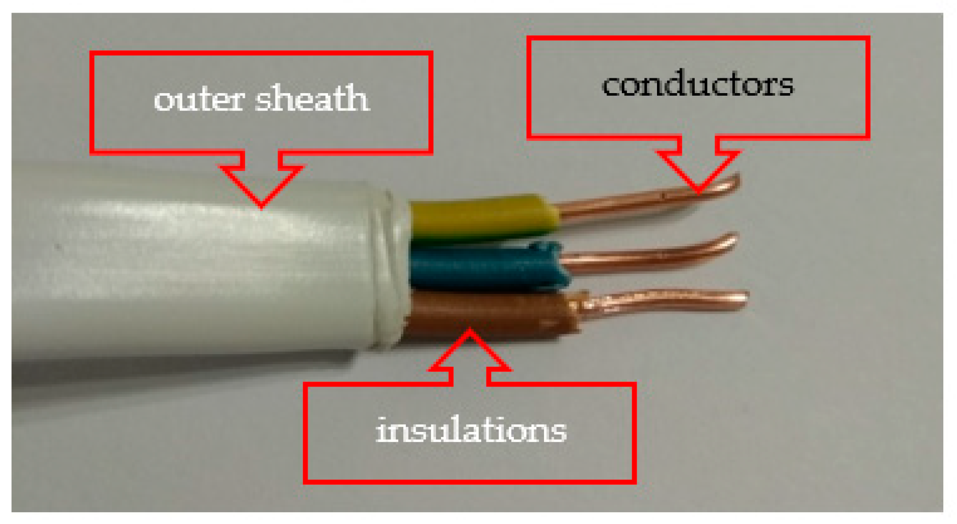
| Cable Size | Cable Dimensions, mm × mm | Weight of Cable, kg/km | Conductors | Insulations | Outer Sheath |
|---|---|---|---|---|---|
| 3 × 1.5 mm2 | 3.8 × 8.5 | 76 | Copper, round, 43.2%w | poly(vinyl chloride), 14.3%w | poly(vinyl chloride), 42.5%w |
| t, min | T, °C | ∆T, °C/min | ||||||
|---|---|---|---|---|---|---|---|---|
| 16 A | 22.4 A | 16 A | 22.4 A | |||||
| (1) | (2) | (3) | (4) | (5) | (6) | (7) | (8) | (9) |
| 0 | ||||||||
| 1 | 23.5 | 24 | 25.5 | 25.5 | - | - | - | - |
| 2 | 24.2 | 24.5 | 26.7 | 26.1 | 0.7 | 0.5 | 1.2 | 0.6 |
| 3 | 25.3 | 25.7 | 31.1 | 27.5 | 1.1 | 1.2 | 4.4 | 1.4 |
| 4 | 27.3 | 27.4 | 37.3 | 29.7 | 2.0 | 1.7 | 6.2 | 2.2 |
| 5 | 29.7 | 29.4 | 44 | 32.6 | 2.4 | 2.0 | 6.7 | 2.9 |
| 6 | 32.3 | 31.5 | 50.7 | 36.1 | 2.6 | 2.1 | 6.7 | 3.5 |
| 7 | 35.1 | 33.5 | 57 | 39.6 | 2.8 | 2.0 | 6.3 | 3.5 |
| 8 | 38 | 35.5 | 64 | 42.6 | 2.9 | 2.0 | 7.0 | 3.0 |
| 9 | 41.2 | 37.3 | 68.4 | 45.9 | 3.2 | 1.8 | 4.4 | 3.3 |
| 10 | 43.6 | 39.2 | 73.9 | 49.2 | 2.4 | 1.9 | 5.5 | 3.3 |
| 11 | 46.3 | 41 | 79.2 | 52.5 | 2.7 | 1.8 | 5.3 | 3.3 |
| 12 | 48.8 | 42.7 | 83.6 | 55.5 | 2.5 | 1.7 | 4.4 | 3.0 |
| 13 | 51.2 | 44.3 | 88 | 58.4 | 2.4 | 1.6 | 4.4 | 2.9 |
| 14 | 53.5 | 45.8 | 92.5 | 61.2 | 2.3 | 1.5 | 4.5 | 2.8 |
| 15 | 55.7 | 47.2 | 96.2 | 63.9 | 2.2 | 1.4 | 3.7 | 2.7 |
| 16 | 57.8 | 48.6 | 99.8 | 66.3 | 2.1 | 1.4 | 3.6 | 2.4 |
| 17 | 59.7 | 49.9 | 103.2 | 68.7 | 1.9 | 1.3 | 3.4 | 2.4 |
| 18 | 61.6 | 51.1 | 106.3 | 70.8 | 1.9 | 1.2 | 3.1 | 2.1 |
| 19 | 63.4 | 52.3 | 109.3 | 72.8 | 1.8 | 1.2 | 3.0 | 2.0 |
| 20 | 65.1 | 53.4 | 112 | 74.8 | 1.7 | 1.1 | 2.7 | 2.0 |
| 21 | 66.8 | 54.5 | 114.6 | 76.4 | 1.7 | 1.1 | 2.6 | 1.6 |
| 22 | 68.3 | 55.5 | 117.2 | 78.1 | 1.5 | 1.0 | 2.6 | 1.7 |
| 23 | 69.8 | 56.5 | 119.6 | 79.6 | 1.5 | 1.0 | 2.4 | 1.5 |
| 24 | 71.1 | 57.5 | 121.6 | 81.2 | 1.3 | 1.0 | 2.0 | 1.6 |
| Class | Parameter |
|---|---|
| A2 and B | FIGRA0.2MJ ≤ 120 W/s THR600s ≤ 7.5 MJ LFS < edge of the specimen |
| C | FIGRA0.2MJ ≤ 250 W/s THR600s ≤ 15 MJ LFS < edge of the specimen |
| D | FIGRA0.4MJ ≤ 750 W/s |
| No | FIGRA0.2MJ;0.4MJ W/s | SMOGRA cm2/s2 | THR600s MJ | Reaction to Fire Class |
|---|---|---|---|---|
| 1 | 1062 | 39 | 66.8 | E or F |
| 2 | 0.0 | 29 | 0.1 | A2 |
| 3 | 376 | 28 | 27.8 | D |
| 4 | 0.0 | 0.0 | 0.5 | A1 or A2 |
Publisher’s Note: MDPI stays neutral with regard to jurisdictional claims in published maps and institutional affiliations. |
© 2020 by the authors. Licensee MDPI, Basel, Switzerland. This article is an open access article distributed under the terms and conditions of the Creative Commons Attribution (CC BY) license (http://creativecommons.org/licenses/by/4.0/).
Share and Cite
Fangrat, J.; Kaczorek-Chrobak, K.; Papis, B.K. Fire Behavior of Electrical Installations in Buildings. Energies 2020, 13, 6433. https://doi.org/10.3390/en13236433
Fangrat J, Kaczorek-Chrobak K, Papis BK. Fire Behavior of Electrical Installations in Buildings. Energies. 2020; 13(23):6433. https://doi.org/10.3390/en13236433
Chicago/Turabian StyleFangrat, Jadwiga, Katarzyna Kaczorek-Chrobak, and Bartłomiej K. Papis. 2020. "Fire Behavior of Electrical Installations in Buildings" Energies 13, no. 23: 6433. https://doi.org/10.3390/en13236433
APA StyleFangrat, J., Kaczorek-Chrobak, K., & Papis, B. K. (2020). Fire Behavior of Electrical Installations in Buildings. Energies, 13(23), 6433. https://doi.org/10.3390/en13236433