Abstract
The fire load of buildings is significantly increased by means of electric cables, usually creating a long combustible base for fire to spread and in this way decreasing the fire safety of buildings. The aim of the study was to evaluate a relationship between the construction of the cables and their fire properties, especially the mass loss influence on other fire properties of cables. Six cables of different core numbers were tested by means of the standard test method EN 50399. Additionally, thermogravimetric analysis and Attenuated Total Reflection—Fourier Transform Infrared analysis were performed on the separate outer sheath, bedding, and core insulations in order to determine the similarity of the materials’ chemical structures. It was found that: (1) the construction of the cable strongly influences the fire behavior due to the creation of a barrier for flame penetration and emission of combustion effluents though inside the closed agglomeration of non-combustible metallic cores (conductors), and the intumescent structures formed from aluminum trihydrate/zinc borate fillers and fire retardants in outer sheath material during the self-sustained combustion process after ignition of cables; (2) the inhomogeneous distribution of non-combustible inorganic fillers or different contents of fillers and flame retardants within the polymer fraction cause an unobvious fire behaviors of cables; and (3) the use of bedding in multicore cable construction results in lower values of combustion parameters (maximum average heat release rate, total heat release, maximum average smoke production rate, total smoke production), e.g., better fire properties of cables.
1. Introduction
The fire load of buildings is significantly increased by means of electric cables, usually creating a long combustible base for fire to spread and in this way decreasing the fire safety of buildings. Since the year 2011, electrical cables and wires have been considered as the construction product [1] and a factor of the fire safety of buildings in Europe. The authors of this article took up the issue of the fire properties of electric cables, and part of the research included in it was presented at the Interflam2019 conference [2].
Cables may self-ignite as a consequence of electrical failure, such as a short circuit in the installation, or another external fire source, for example, a burning item. Because of their applications, they are potentially a danger in the case of fire, especially when installed in cable trays [3]. Therefore, such products are an important element in ensuring the fire safety of buildings [4]. A major concern is the selection of electric cables used in buildings according to their fire properties.
The number of small- and full-scale tests for measuring heat, smoke, and fire spread has been developed for a better understanding of the fire behavior of electric cables. The behavior of cables has been widely investigated horizontally, i.e., the cone calorimeter method, which shows a good reproducibility and repeatability in the case of cable testing.
The previous investigations pointed out that cables presenting non-planar surfaces would experience significantly different heat flux levels during cone calorimeter tests [5]. It was found that the time to ignition is only dependent on heat flux and the influence of the sheath is pointed out to delay the occurrence of the main peak of the heat release rate corresponding to the decomposition of non-flame retarded insulation [6]. Under the other investigation, the high influence of heat flux and the composition and structure of the cable was found as well as the dependency of the fire properties of cables and the change in the cable specimen layout for cone calorimeter testing [7]. In most cases, cone calorimeter equipment was the relevant method for estimating the full-scale fire behavior of various products [8,9], such as cables. The main problem in the case of the fire properties of electric cables is always how to transfer reasonable data to a real-scale scenario.
The main cable construction elements, such as insulation, outer sheath, and, optionally, bedding (inner covering), are built of non-metallic materials (synthetic). The needs for improvement of the processability, flame retardancy, and physical and mechanical properties forced the creation of modern polymeric materials that meet certain requirements. The improved performance of cable compounds can be made by using the intumescent technology and synthetic nanomaterials [10].
A commonly used material for low-smoke zero-halogen (LS0H) cable outer sheath formulation is ethylene-vinyl acetate copolymer containing vinyl acetate (EVA), aluminum trihydride (ATH), and zinc borate (ZnB). Zinc borate has a synergistic effect with aluminum hydroxide and is often used in combination with other flame retardants. Zinc borate behaves like aluminum hydroxide by endothermic release of water, but its main flame retardant effect results from the formation of a glassy layer on the material surface [11,12].
ATH is the most widely used inorganic flame retardant because of its low cost and easy incorporation into plastics. The fire retardancy mechanism is based on the release of water in the reaction of thermal decomposition (1). The released water excludes air and dilutes the flammable gases. This endothermic reaction results in stable high-temperature intumescent Al2O3 layer Equation [11,12]:
2Al(OH)3 → Al2O3 + 3H2O.
In many cases, cables made of the same materials, but with a different construction, exhibit different fire properties, such as heat release and smoke production [3,13].
2. Research Problem
Cables, in case of their constructional material parameters, such as: conductor shape, type of materials used for their formulation, voltage rate, and concentric barrier occurrence, are grouped into so-called “cable families” [14], because cables have more complex fire behavior than other building elements. It is, however, not certain whether the worst fire parameter results for the chosen cables are due to a constructional parameter, such as the cable diameter (d) or the number of conductors (n) [15].
The fire properties of each cable are expressed as the so-called cable parameter χ (2) [14]. The cable parameter was invented to predict the monotonical trend of fire parameters obtained during the EN 50399 standard test of cables within the same cable family [14]:
where:
- d—cable diameter, m;
- Vcombust—non-metallic volume of cable components (combustible), m3/1m bunched cable according to EN 50399 [16];
- n—number of cores (conductors).
Equation (2) contains the main properties characterizing the cable (n, d), and the component that expresses the volume of combustible materials (Vcombust), which influence its fire properties.
The cable parameter has been shown to be more complex than a simple cable diameter (d) and non-metallic volume (Vcombust) in the case of selecting cable samples for testing within the identified cable family [15].
The authors published the study focused on explaining a relationship between the construction of the cables and their fire properties [4,17]. In this article, the problem of mass loss in relation to fire properties is discussed in detail. In the study presented in this article, the authors focused on the problem of deterioration of fire properties as the amount of flammable materials in the construction increases, and also considered the selection of the most important factors affecting the fire properties of electric cables.
3. Experimental Section
In order to determine the fire properties of electric cables, full-scale tests were performed on cables installed in bundles using the equipment specified in EN 50399 [16].
3.1. Samples
Fire-resistant power and control non-halogenated cables were taken into investigation. Samples were chosen to represent the possible range of cables produced and typically used in Europe for fire detection systems.
Six electric cables of various constructions (Table 1, Figure 1 and Figure 2) having the same type of conductor, sheath, and insulation were chosen for the experiments as typical electric cables used in buildings. The series of tests were performed by means of three experimental methods as described below. Each tested cable was constructed of copper wire(s), primary mica tape core insulations, main insulation formed of cross-linked polyolefin compounds, bedding (except 1-core cable) made of flame-retarded cross-linked poly(ethylene), and the outer sheath based on ethylene/vinyl/acetate (EVA) copolymer filled with aluminum trihydrate (ATH) and zinc borate (ZnB) as a flame retardant.

Table 1.
Characteristics of cable samples: copper cores class 1, sheath made of EVA/ATH/ZnB compound, insulation made of mica tape, and silane cross-linked polyolefin (XLPO) compound.

Figure 1.
View of the cross-sections of the cables.
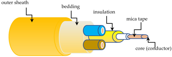
Figure 2.
Schematic of the 3-conductor cable sample.
3.2. Methods
Typical thermo-gravimetric analysis (TGA) and Fourier transform infrared (FTIR) spectrometry (Figure 3a,b) as well as large-scale vertical fire spread experiments according to EN 50399 were performed.
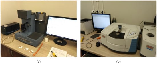
Figure 3.
Small-scale instrumental equipment at the accredited ITB Fire Laboratory, Poland: (a) TGA; (b) FTIR;
3.2.1. Small-Scale Experiments
The similarity of the main construction parts of cables, e.g., outer sheaths, beddings, and core insulation, was assessed by thermo-gravimetric analysis (TGA) in the nitrogen atmosphere supplemented with Fourier transform infrared (FTIR) spectrometry based on the “fingerprint” analysis. A small piece of each polymeric material was required for both analytical tests.
For TGA analysis, the weight of the load material did not exceed 90 mg. A chemically and thermally neutral alumina pan was used for transportation of the specimen into a furnace, and a 50 °C/min heating rate up to 1000 °C was applied for the decomposition processes. The high heating rate was chosen to reflect the heating rate observed in fire conditions [18].
Additionally, the attenuated total reflectance (ATR) method for FTIR spectroscopy analysis was used for qualitative analysis. Specimens were tested on a diamond crystal and 16 scans per sample were applied. The top layer of each tested material was scrapped and washed in acetone before the analysis to avoid interference caused by grease and any other dirt on the specimen surfaces.
The thermal decomposition of each cable element was measured as oxidative mass losses was a function of increasing temperature (Figure 4a,b and Figure 5).
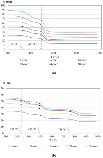
Figure 4.
TGA curves of cable materials: (a) outer sheaths; (b) beddings.
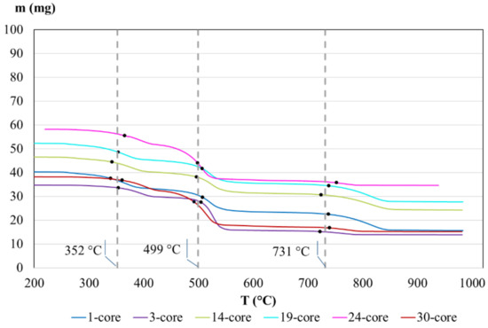
Figure 5.
TGA curves of core insulations of tested cables.
The profiles of the TGA curves for the outer sheaths and bedding of the tested cables (Figure 4a,b) are similar in each case. The vertical lines show two characteristic onset temperatures indicating the extrapolated temperatures of the beginning of the processes, where the preliminary and further steps of thermal decomposition of the material took place. They represent the similar trends of decomposition temperatures of each sheathing material, which indicated the same composition of each non-metallic sheathing element of the tested cables. The mass loss of those compounds oscillated between 56% for 19- and 24-core cable and 60% for 1-core cable. About 40% of the sheaths are incombustible inorganic fillers. This observation pointed out there is no significant difference in the chemical composition between the outer sheaths of cables, but the distribution of inorganic fillers is uneven. In the case of beddings (Figure 4b), three characteristic temperatures of decomposition reactions were observed: about 335, 496, and 758 °C, which is shown as vertical trend lines. The mass loss of the bedding compounds of the tested cables was similar in each case (about 44–48%).
The largest differences between mass losses in TGA analysis of insulations were observed (Figure 5) between 1-, 3-, and 30-core cables (about 60%) and 14- and 19-core cables (about 47%). The lowest mass loss, equal to 40%, was observed for 24-core cable. The reason is probably due to the inaccurate distribution of inorganic fillers or even the different content of filler within the polymer fraction. However, the results in temperature levels when decomposition starts are similar in each case, as follows: 352, 499, and 731 °C.
The characteristic temperatures of decomposition (onset temperatures) of materials used for formulation of outer sheaths, beddings, and core insulations were mostly similar for each tested cable.
The ATR-FTIR spectra for each tested construction material of cables (a “fingerprint” method) were used for the materials’ similarity confirmation (Figure 6, Figure 7 and Figure 8). Characteristic absorbance (Abs) bands appearing at specific wave numbers characterized the single chemical bonds in the materials used for cable formulation.
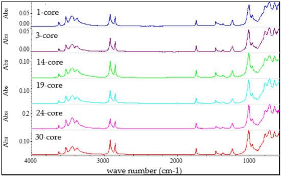
Figure 6.
FTIR spectra of the outer sheath of the tested cables.
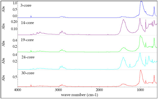
Figure 7.
FTIR spectra of the bedding of tested cables.
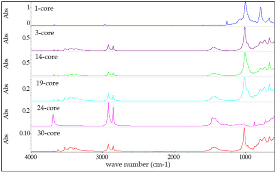
Figure 8.
FTIR spectra of core insulations of tested cables.
A very good correlation between each outer sheath spectrum is shown (Figure 6). The wave numbers and absorbance bands were similar. The correlation factor for outer sheaths (more than 0.91) pointed out the similarity of materials used for sheath formulation.
The wave numbers of characteristic bands from bedding samples (Figure 7) are similar for each tested cable. However, the intensity (absorbance) of the bands point to differences in the amount of chemical species content within the polymer fraction.
The similar distribution of bands and the changes in the intensity of characteristic bands on the spectra were observed in the case of cable insulations (Figure 8). This observation can also be explained by differences in the amount of chemical species in both bedding and core insulation materials.
Those comparisons simply show the similarity of the materials used for cable formulation. The differences between decomposition temperatures and mass losses at TGA analysis and the changes in the intensity (absorbance) of the FTIR band shows a difference in inorganic fillers (even 60% for 1, 3-, and 30-core cable insulations). This large amount of incombustible fillers (mainly ATH) also influences the fire properties of cables, reducing their flammability.
3.2.2. Large-Scale Experiments
The test method described in EN 50399 standard (Figure 9a) was chosen for the full-scale experiments because the cables were tested in the configurations (cable trays) as they are used in reality as a whole product (Figure 9b) [19].
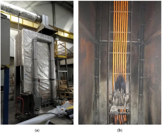
Figure 9.
EN 50399 standard test apparatus at the ITB Fire Laboratory, Poland: (a) test chamber; (b) specimen No 4 after the test (numbering according to Table 1).
Cables were installed in bundles on the standard ladder width of 500 mm under the specified installation conditions [5]. The burner nominal heat release rate level of 20.5 kW, airflow rate through the chamber of (8000 ± 800) L/min, and the white light detector were used [15,16]. Cable specimens were ignited from the front side by the burner initially, with most heat being emitted on the front side. The CO2 concentration was measured using a non-dispersive infrared (NDIR) spectrometer and oxygen depletion by a paramagnetic analyzer.
The following parameters and observations were registered during each large-scale cable experiment:
- -
- Heat production: peakHRRav, THR1200s;
- -
- Smoke emission: peakSPRav, TSP1200s;
- -
- Presence of burning droplets; and
- -
- Range of flame spread FS.
THR1200s (MJ) is the total heat release from the specimen in the total 1200 s of exposure to the main (primary) burner flames, whereas the peakHRRav (kW) is a maximum average heat release rate. TSP1200s (m2) is the total smoke production from the specimen in the total 1200 s of exposure to the main (primary) burner flames and peakSPRav (m2/s) is the maximum smoke production rate. Determining the rate of heat release using the calorimetric method involves measurement of the loss of oxygen as a fuel in the combustion process. The mass flow and oxygen concentration in the extraction system allows continuous estimation of the amount of heat released [20]. The single test according to EN 50399 standard of each cable built of the same materials and the same voltage rating (0.6/1kV) was performed (Table 1), except the 19-core cables, where two specimens were taken to check the additional confirmation of the test results (Table 2). Each single test duration took 20 min from the burner start.

Table 2.
Comparison of EN 50399 test results obtained for two specimens of 19-core cable.
All of the presented results (Table 2) are relatively low and good reproducibility of the maximum average heat release rate, total heat release, and flame spread (FS) were obtained. The differences between the peakHRRav are about 6%, which is within the uncertainty of the test method.
Among the tested samples, the highest value of peakHRRav = 137.4 kW and peakSPRav = 0.13 m2/s was obtained for the 1-core cable. According to the definition of Vcombust (non-metallic content), the measured value of heat release rate should increase with the value of Vcombust. The experimental results (Figure 10a,b), however, present a different behavior. The minimum peakHRRav value was found for 19-core cable (equal to 7 kW) and the peakHRRav value increases with Vcombust for cables with more than 19 cores.
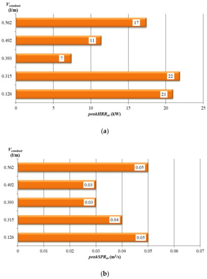
Figure 10.
Tested cables vs. their non-metallic volume Vcombust: (a) peakHRRav; (b) peakSPRav.
A similar dependency was found in the case of the total heat release rate THR1200s, the effective heat of combustion (EHC), and flame spread (FS) for cables differing in the number of cores (Table 3).

Table 3.
Details of the experimental results for tested cables with the growing non-metallic volume Vcombust.
The relationship between the maximum average heat release rate and maximum average smoke release rate for the tested (low-smoke zero-halogen) cables varies in the number of copper cores (conductors) and their non-metallic volume and the total heat release as a function of the non-metallic volume for the same cables (Table 3) is similar in both cases.
The minimum value of total smoke production TSP1200s (Table 3) and maximum average smoke production rate (Figure 10b) were recorded for the 19- and 24-core specimens. However, the peakSPRav values are relatively low in the case of each tested cable with more than one core.
The average speed of flame spread (vav) was calculated as the flame spread (FS) obtained during the 20-min test duration when the burner was applied. The maximum vav (equal to 0.17 m/min) was obtained for the 1-core cable, which does not consist of bedding (inner covering), which has an effect on the cables’ fire properties by increasing the tight packing inside the cable, thus not allowing the flame to penetrate to the inner layers of the cables.
4. Discussion and Conclusions
The TGA and ATR-FTIR analysis indicate that there were no significant differences between the chemical formulations between the outer sheaths and beddings for cables subjected to testing in a small and large geometrical scale. Small differences in the core insulations’ composition were shown. It could be explained by the inhomogeneous distribution of inorganic fillers or different content of fillers within the polymer fraction. The large amount of incombustible fillers used in the sample cables (mainly ATH) strongly influences the fire properties of the cables, reducing their flammability.
The first step in thermal decomposition in each case is the release of water at the temperature of 300 °C during the ATH thermal decomposition reaction from each non-metallic element of cables. As a result of the decomposition of the compound, water vapor is formed, which lowers the temperature of the burning element, and also dilutes the resulting fumes. The zinc borate forms the glassy layer, which prevents the assessment of flame and acts as a smoke suppressant [11,21]. Mainly, zinc borates reduce the heat release rate and smoke generation in most metal hydroxide-containing polymers [22].
An unobvious relationship between the fire properties and non-metallic volume of the cables (Vcombust) made out of the same materials was observed. For 1-core cables, which consist only of an outer sheath and core insulation, the highest values of heat, smoke parameters, and parameters related to the flame spread of the cables were obtained, whereas the lowest values of peakHRRav, THR1200s, EHC, and FS were determined for cables with 19 cores. Similar results were observed for total smoke production. This phenomenon can be explained by the compact structure caused by the close packaging of copper cores (conductors) in the case of multicore cables, which creates a barrier for flame penetration inside the closed agglomeration of metallic wires. This is also a reason for the difficult access of oxygen to the combustion zone and difficult emission of volatile combustion products. The presence of the filling compound (bedding) results in much lower values of the parameters characterizing the combustion process (peakHRRav, THR1200s, peakSPRav, and TSP1200s) than for the 1-core cable, where the flame penetrated the sample cross section without additional barriers.
The same tendency was observed for cables with more than 19 cores, where the heat release parameters increased together with the non-metallic volume of the cables. This phenomenon is additionally accelerated by the intumescent structure formulation from ATH fillers, which, in the case of fire, are shown as a residue in TGA analysis of each cable construction material. The obvious conclusion is that the more ATH fillers in non-metallic combustible materials, the better the fire properties obtained. The role of ZnB filler as a flame retardant must also be underlined.
It could, therefore, be argued that to some extent, the construction of the cable, especially the number of cores, as well as the amount of incombustible fillers, influences the final fire behavior of cables because they form a barrier against the external flames penetrating the cable before ignition.
In the course of the analysis, it was found that the fire properties based only on the existing cable parameter χ are determined in a not very precise manner. The number of conductors, cable diameter, and Vcombust are not sufficient parameters to describe these properties. The approximate amount of polymer combustible material needs to be estimated and the cable construction needs to be taken into account for a more precise evaluation of the fire properties of cables.
The following conclusions from this research can be drawn:
- The construction of the cable strongly influences the fire behavior due to the creation of a barrier for flame penetration and emission of combustion effluents though:
- a.
- Inside the closed agglomeration of non-combustible metallic cores (conductors);
- b.
- The intumescent structures formed from ATH/ZnB fillers and fire retardants in outer sheath material during the self-sustained combustion process after the ignition of cables;
- The inhomogeneous distribution of non-combustible inorganic fillers or different contents of fillers and flame retardants within the polymer fraction cause an unobvious fire behavior of cables;
- The amount of organic combustible compounds strongly influences smoke production during the combustion processes;
- The use of bedding in multicore cable construction results in lower values of combustion parameters (peakHRRav, THR1200s, peakSPRav, and TSP1200s), e.g., better fire properties of cables.
The performed experiments enabled the development of a new concept of the cable parameter, which is a more precise predictive indicator of cable flammability than the standardized cable parameter χ, which inadequately describes the fire properties of electric cables. Further studies shall be focused on the development of a new cable parameter based on the mass loss data obtained using TGA analysis. Moreover, the parameters of cables, which are useful in fire modelling, should be defined, as well as the numerical modelling procedure based on Quintiere’s theory adopted for electric cables.
The results of the presented study can be useful for researchers interested in this subject as well as producers, engineers, designers, independent consultants, approving authorities, and policy makers.
Author Contributions
Conceptualization, methodology, formal analysis, investigation, resources, data curation, writing—original draft preparation, writing—review and editing, K.K.-C.; supervision, conceptualization, writing—review and editing, J.F. All authors have read and agreed to the published version of the manuscript.
Funding
This research did not receive funding.
Conflicts of Interest
The authors declare no conflict of interest.
References
- Regulation (EU) No 305/2011 of the European Parliament and of the Council of 9 March 2011 Laying Down Harmonised Conditions for the Marketing of Construction Products and Repealing Council Directive 89/106/EEC. Available online: https://eur-lex.europa.eu/legal-content/EN/TXT/HTML/?uri=CELEX:32011R0305&from=EN (accessed on 29 September 2020).
- Kaczorek-Chrobak, K.; Fangrat, J. Relationship between Non-Metallic Material Content and Fire Properties of Electric Cables. In Proceedings of the INTERFLAM2019 Conference, London, UK, 1–3 July 2019. [Google Scholar]
- Bourbigot, S.; Sarazin, J.; Bachelet, P. Small Scale Evaluation and Characterization of Simulated Low Voltage Cables with and without Electrical Current. Fire Mater. 2015, 12, 12–22. [Google Scholar]
- Kaczorek-Chrobak, K. Electric Cables Used in Buildings—Dependency of Fire Properties on Constructional and Material Parameters. Ph.D. Thesis, Instytut Techniki Budowlanej, Warsaw, Poland, 2020. [Google Scholar]
- Grayson, S.J.; Van Hees, P.; Green, A.M.; Vercellotti, U. Assessing the Fire Performance of Electric Cables (FIPEC). Fire Mater. 2001, 25, 49–60. [Google Scholar] [CrossRef]
- Carcillo, M.; Caro, A.-S.; Sonnier, R.; Ferry, L.; Gesta, E.; Lagreve, C. Fire behaviour of electrical cables in cone calorimeter: Influence of cables structure and layout. Fire Saf. J. 2018, 99, 12–21. [Google Scholar]
- Meinier, R.; Sonnier, R.; Zavaleta, P.; Suard, S.; Ferry, L. Fire behavior of halogen-free flame retardant electrical cables with the cone calorimeter. J. Hazard. Mater. 2018, 342, 306–316. [Google Scholar] [CrossRef]
- Braun, E.; Shields, J.R.; Harris, R.H. Flammability Characteristics of Electrical Cables Using the Cone Calorimeter; NIST Report, NISTIR 88 4003; Department of Commerce: Washington, DC, USA, 1989.
- Hirshler, M.M. Survey of fire testing of electrical cables. Fire Mater. 1992, 16, 107–118. [Google Scholar] [CrossRef]
- Cogen, J.M.; Jow, J.; Lin, T.S.; Whaley, P.D. New Approaches to Halogen Free Polyolefin Flame Retardant Wire and Cable Compounds. In Proceedings of the 52nd IWCS/Focus International Wire and Cable Symposium, Philadelphia, PA, USA, 13 November 2003; pp. 102–107. [Google Scholar]
- McCarthy, S. Environmentally Benign Resins and Additives, For Use in the Wire and Cable Industry; Technical Report; The Massachusetts Toxics Use Reduction Institute University of Massachusetts Lowell: Amhrest, MA, USA, 2003. [Google Scholar]
- Kaczorek, K. Bench Scale Fire Toxicity Measurements of Polymers and Cables. Master’s Thesis, University of Central Lancashire, Preston, UK, 2009. [Google Scholar]
- Kaczorek-Chrobak, K. Reakcja na ogień kabli bezhalogenowych oraz kabli na bazie PVC (Reaction to fire of PVC based halogen-free electric cables). Elektroinfo 2015, 10, 25–27. (In Polish) [Google Scholar]
- CLC/TS 50576 Electric Cables—Extended Application of Test Results for Reaction to Fire. Available online: https://shop.bsigroup.com/ProductDetail?pid=000000000030340235 (accessed on 23 November 2020).
- Sundström, B.-A.; Försth, M.; Johansson, P.; Grayson, S.; Journeaux, T. Prediction of Fire Classification of Cables. Extended Application of Test Data. In Proceedings of the 12th International Fire Science & Engineering Conference, Nottingham, UK, 5–7 July 2010. [Google Scholar]
- EN 50399. Common Test Methods for Cables Under Fire Conditions—Heat Release and Smoke Production Measurement on Cables During Flame Spread Test—Test Apparatus, Procedures, Results. Available online: https://standards.iteh.ai/catalog/standards/clc/aec73708-d180-4cf3-b532-fb0850ed0705/pren-50399 (accessed on 23 November 2020).
- Kaczorek-Chrobak, K.; Fangrat, J. Influence of Constructional-Material Parameters on the Fire Properties of Electric Cables. Energies 2019, 12, 4569. [Google Scholar] [CrossRef]
- Girardin, B.; Fontaine, G.; Duquesne, S.; Bourbigot, S.; Delineau, L.; Försth, M.; Hewitt, F.; Witkowski, A.; Stec, A.; Hull, T.R. Small scale tests and numerical modelling of fire performance for electrical cable. In Proceedings of the 14th International Conference and Exhibition on Fire and Materials, San Francisco, CA, USA, 2–4 February 2015. [Google Scholar]
- Försth, M.; Sjostrom, J.; Wickstrom, U.; Anderssoon, P.; Girardin, B. Characterization of the thermal exposure in the EN 50399 cable test apparatus. In Proceedings of the International Conference and Exhibition on Fire and Materials, San Francisco, CA, USA, 2–4 February 2015; pp. 23–37. [Google Scholar]
- Janssens, M.; Parker, W.J. Oxygen Consumption Calorimetry. In Heat Release in Fires; Babrauskas, V., Grayson, S.J., Eds.; Elsevier Applied Science: London, UK, 1992; pp. 31–59. [Google Scholar]
- Yang, Y.; Shi, X.; Zhao, R. Flame Retardancy Behavior of Zinc Borate. J. Fire Sci. 1999, 17, 355–361. [Google Scholar] [CrossRef]
- Shen, K.K. Review of Recent Advances on the Use of Boron-based Flame Retardants. Polym. Green Flame Retard. 2014, 367–388. [Google Scholar] [CrossRef]
Publisher’s Note: MDPI stays neutral with regard to jurisdictional claims in published maps and institutional affiliations. |
© 2020 by the authors. Licensee MDPI, Basel, Switzerland. This article is an open access article distributed under the terms and conditions of the Creative Commons Attribution (CC BY) license (http://creativecommons.org/licenses/by/4.0/).