Article

Gel Pills for Downhole Pressure Control during Oil and Gas Well Drilling

1
Department of Energy and Petroleum Engineering, University of Stavanger, NO-4036 Stavanger, Norway
2
Equinor, NO-4035 Stavanger, Norway
*
Author to whom correspondence should be addressed.
Energies 2020, 13(23), 6318; https://doi.org/10.3390/en13236318
Submission received: 24 October 2020 / Revised: 24 November 2020 / Accepted: 26 November 2020 / Published: 30 November 2020
(This article belongs to the Special Issue Recent Advances in Petroleum Drilling Engineering)

Abstract

:
During drilling of petroleum or geothermal wells, unforeseen circumstances occasionally happen that require suspension of the operation. When the drilling fluid is left in a static condition, solid material like barite may settle out of the fluid. Consequently, the induced hydrostatic pressure that the fluid exerts onto the formation will be reduced, possibly leading to collapse of the borehole or influx of liquid or gas. A possible mitigation action is placement of a gel pill. This gel pill should preferably be able to let settled barite rest on top of it and still transmit the hydrostatic pressure to the well bottom. A bentonite-based gel pill is developed, preventing flow of higher density drilling fluid placed above it to bypass the gel pill. Its rheological behavior was characterized prior to functional testing. The designed gel pill develops sufficient gel structure to accommodate the settled barite. The performance of the gel was tested at vertical and 40° inclination from vertical. Both conventional settling and the Boycott effect were observed. The gel pill provided its intended functionality while barite was settling out of the drilling fluid on top of this gel pill. The barite was then resting on top of the gel pill. It is demonstrated that a purely viscous pill should not be used for separating a high density fluid from a lighter fluid underneath. However, a bentonite or laponite gel pill can be placed into a well for temporary prevention of such intermixing.

1. Introduction

Drilling fluids are concentrated fluid–solid mixture whereas high density minerals such as barite with a density of 4.2 s.g. (specific gravity) are used to increase and adjust the density of drilling fluid. As density of the heavy minerals is much higher than the fluid density, gravitational force acts on these particles making them segregate and finally settle out of the fluid. A review of the phenomenon, better known as weighting material sag, and possible measurement methods is found by consulting Ofei et al. [1]. The sagging effect occurs both in water-based and oil-based drilling fluids. However, it appears to happen faster in oil-based drilling fluids [2,3]. Saasen et al. [4] showed that barite sag can be more intense in fluids that develop fragile gel structures when left static. They defined a fragile gel structure fluid as a fluid with high gel strength, but when the initial gel structure is ruptured, the remaining gel structures will easily break. Thus, a drilling fluid may have high gel strength, but when exposed to small shear rates, its solid particles can start to settle fast. Barite settling is known to cause problems during drilling operations with the most severe consequence leading to well control issues. This is due to the reduction of hydrostatic pressure exerted by the drilling fluid.
The sag phenomenon in a vertical, static drilling fluid column is controlled by viscosity and gel formation. As the barite particles move downwards because of gravity, a fluid motion is set up in the opposite direction to preserve the fluid mass balance. This counterflow may contain solid particles smaller than the sagging particles. Hence, the sag velocity is reduced. This is illustrated in Figure 1a. If the static fluid column is inside a tilted pipe, the sag will be accelerated by the so-called Boycott effect [5]. If the barite particles travel vertically downwards, a less dense fluid layer will be placed above a denser layer in a tilted tube. This will trigger a flow of light fluid upwards and a dense fluid downwards in the well, as illustrated in Figure 1b, accelerating the settling process. This process continues until most weight material particles have reached the well bottom.
As barite starts to settle out from drilling fluid, the uniform distribution of barite decays resulting in a higher density fluid at the lower part and a lower density fluid at the higher part of the fluid column. This results in a static fluid system that no longer provides a constant hydrostatic pressure gradient throughout the fluid column. When the barite particles rest on a bed, the hydrostatic pressure of fluid column will be lost. This phenomenon can lead to the well bore pressure being in underbalance with respect to formation pressure, potentially causing influx of liquid or gas into the well.
The intensity of barite sedimentation is function of drilling fluid characteristics, such as particle size, concentration of particles, surface charge of particles, and operational circumstances such as flowrate or induced stresses caused by drilling activities, and distance between the particle and bedding distance [4,5,6,7]. Nguyen et al. [8] showed that if the fluid is left in static conditions, the barite sag will not occur if the yield stress of the fluid is higher than approximately 6 Pa (12 lbf/100 ft2). This statement, however, shows the difficulty in determination of the yield stress. By a force balance, it is easily shown that the barite particle should not move if it is exposed to a fluid with a real yield stress exceeding half a Pascal.
Previous studies on barite sedimentation mechanisms showed that in inclined pipes, from vertical to 20° and 40°, the contribution of gravity and Boycott effect on barite settling was observed. It was also observed that the hindered mechanism affected the settling time on the suspended barite particles in water-based drilling fluids as inclination was changed from 40° to vertical [5,9]. In drilling operations, there are circumstances where maintaining the hydrostatic pressure profile at the bottom of well or at a desired depth is necessary when the drilling operation is temporarily suspended.
A viscous pill has been tried as a liquid packer placed above the formation with influx potential, to collect the sagging weight material and thus provide proper pressure at this formation. However, a viscous fluid alone will be prone to Rayleigh–Taylor instability [10] where the dense fluid will flow downward, and the lighter fluid will flow upward. The interface will be even more unstable if it is placed in a deviated section as longer disturbance lengths are less stable than the shorter; this also occurs in the case of polymeric liquids [11,12]. This was the reason for the use of the umbrella-like tool placed in the well for plug cementing purposes [13].
A proper gel pill could be placed just above the formation with the potential of fluid influx, and would hold the settled barite while ideally still transmitting the pressure exerted by the fluid and barite above the pill to the formation below the pill. This pill needs to be properly gelled to prevent formation of Rayleigh–Taylor instability. Gel is defined as a soft colloid that is elastic, deformable, and solid. It is made of colloidal particles together with polymers, which together construct a nonliquid network. When considering the microstructure of gel at microscale, it is “liquid,” and when considering it at macroscale, it is “solid” [14]. A viscous fluid is liquid with a relatively high viscosity. A viscous pill is usually used for special tasks such as cuttings transportation, lost circulation treatment, or removing filter cakes.
Fosso et al. [15] emphasized that for a Bingham plastic with a proper yield stress of τ y in a pipe with diameter of D, if the pressure gradient does not exceed 4 τ y D , the fluid above the gel pill will remain in stable condition and no flow will occur. A yield stress is the minimum gel strength of a material. Harestad et al. [13] showed that the maximum pressure difference the gel ideally needs to hold is a density difference across the well cross-section if the fluid above the gel is carefully positioned. Hence, the necessary length of a gel pill is as short as possible to ensure proper placement over the entire pill length.
Inside a pipe, a proper gel pill will always hold back a pressure difference equal to the value shown in Equation (1):
Δ p = 4 τ g D Δ L
where τ g is the gel strength, D is the pipe diameter, and Δ L is the pill length. This equation is found by conducting a simple force balance.
Settled barite may prevent the force transmission. For a layer of completely settled barite particles, any force transmission will be conducted through direct particle–particle contacts. Since these particles have different shapes and sizes, it is not possible to exactly predict the angle of attack between the particles. However, it is anticipated that this would be around 45°. Therefore, pressure transmission may be hindered when the height of the settled barite exceeds the pipe diameter. Any pressure increase after this condition has occurred will only apply more normal forces on the pipe wall.
The primary objective of this study was to evaluate a pressure transmitting gel pill that can act as a resting bed for settled barite particles. In addition, the gel pill should prevent any tendency for Rayleigh–Taylor instability or breakthrough of sagged barite staying on top of the gel pill. The gel pill should establish full pressure transmission of the overlying fluid column to maintain constant hydrostatic pressure underneath the pill. Subobjectives were to evaluate a gel pill with low viscosity during placement and high viscosity and gel strength after placement.

2. Experiments with Viscous Pills and Gel Pills

2.1. Benchtop Viscous Pill Test Overview

In practical operations, it has been common to apply viscous pills to prevent segregation of other fluids with higher density from above. In this section, it will be shown that use of viscous pills is insufficient to prevent a high density fluid to swap position with a lighter fluid underneath. This is demonstrated by placing a viscous pill in a benchtop tube. Thereafter, a 1.48 s.g. fluid is placed on top of the pill and measure if it will stay in place. A short wavelength disturbance is more stable than a long wavelength disturbance [11,12]. The wavelength of the disturbance will depend on the length of the interface between the fluids; the larger the diameter, the larger the wavelength. If the interface is unstable in the benchtop experiments, it will also be unstable in the larger scale tests. Therefore, only the successful cases from the benchtop tests were repeated in larger scale equipment tests.

2.2. Model Drilling Fluid and Viscous Pills

All of the fluids consist of tap water and Xanthan biopolymer. The model drilling fluid contains added barite to a density equal to 1.48 s.g. The full composition of the model drilling fluid is shown in Table 1. The viscous properties initially after mixing and after 24 h storage are illustrated by the flow curves shown in Figure 2. By comparing these flow curves with the huge number of flow curves of practical drilling fluids shown by Saasen and Ytrehus [16], it is shown that this model drilling fluid has a very low viscosity. This is beneficial for the experiments as the low viscosity promotes instability. Hence, the ability of the viscous or gel pill to hinder swapping of the fluids becomes more clearly visible.
The laboratory viscous pill formulations are shown in Table 2. Their flow curves are shown in Figure 3. Pill 1 has a viscosity behavior typically for a polymer-rich water-based drilling fluid, while pill 2 is far more viscous, the latter being too viscous to have the shear stress measured at the highest shear rate on an oilfield viscometer.
To prepare the fluids, a Heidolf Torque 100 mixer was used to mix small volumes and provide enough mixing energy to create the desired rheological behavior. For the larger scale testing, a Hobart mixer model N50-60 was used with a low stirring rate. The mixers have a type of blade which minimizes the physical damage to bentonite and laponite. The viscosity was measured using an Ofite 900 viscometer. The measurements were done at ambient conditions.

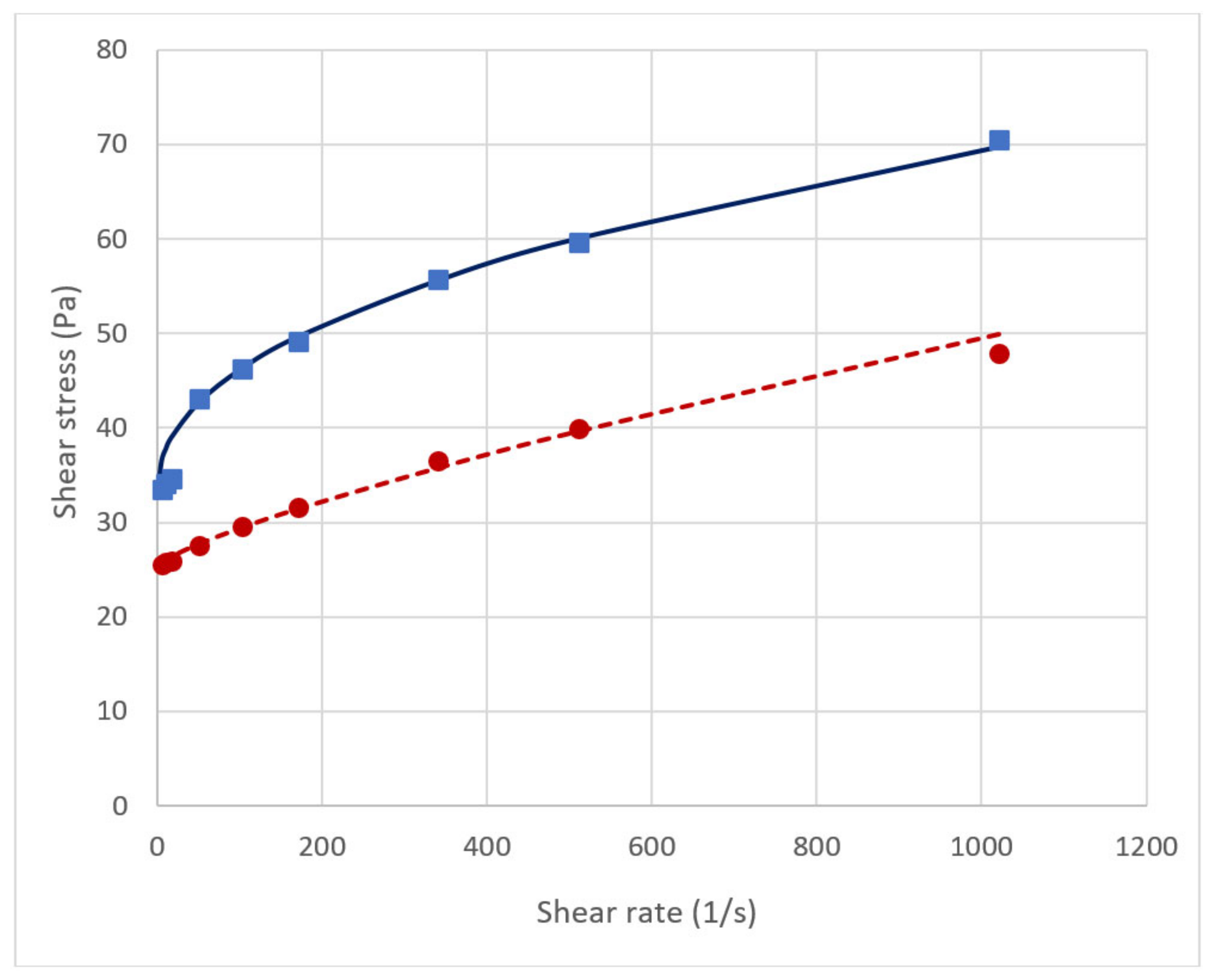
2.3. Performance of the Viscous Pills in the Benchtop Tests

The effect of the viscous pills was tested in a 0.5 m long benchtop tube with 50 mm inner diameter, as illustrated in Figure 4. The viscous pill was positioned at the bottom of the tube. Thereafter a volume of the model drilling fluid was placed above the viscous pill. Both for Pill 1 and the very viscous Pill 2, the fluid volumes immediately swapped positions. Figure 2 shows a picture of the final test result for Pill 2, photographed just after the swapping had occurred. As explained earlier, if the diameter had increased or if the hole angle deviated from vertical, the fluid case would be more unstable as the case becomes more unstable if longer wavelength disturbances are possible [11,12]. Hence, there was no use testing the viscous pills in larger holes or deviated holes.

2.4. Design and Development of Bentonite-Based Gel Pill

As described earlier, the scope was to construct a gel pill that can act as a resting bed for settled barite particles from the drilling fluid volume placed above the gel pill. To evaluate the desired properties of this gel pill, it was necessary to perform laboratory tests. Bentonite gels were found to be good candidates for such pills. Conventional bentonite pills will not be transparent and thus any sag effects of barite within the pill will be difficult to observe. Therefore, experiments were also performed using a transparent bentonite system. This was performed using the synthetic clay laponite [17] to make similar gel pills for laboratory investigations. The laponite gel pills should ideally have nearly the same rheological properties as the conventional bentonite pill. This pill was tested in a laboratory model representing a well bore at various inclinations. A viscosified brine volume was placed beneath the gel pill. The brine is used to increase the density contrast to the model drilling fluid placed above the gel pill and to simulate the presence of a low density drilling fluid volume left in the lower section of the hole. As explained earlier, the model drilling fluid placed above the gel pill is also a simple fluid using barite to increase the density. This fluid will not produce any significant gel strengths and will therefore increase the possibility of triggering Rayleigh–Taylor instability, and hence, provide a good test for the performance of the gel pill.
The gel pill designed for practical use was based on a conventional bentonite (Table 3). Bentonite consists of clay minerals, predominantly montmorillonite with minor amounts of other smectite group minerals, often used in drilling fluids to control the filter loss and viscosity of the fluid [18]. An API bentonite was used in this study. Different concentrations of bentonite were added to a base fluid. Their rheological behavior was characterized by use of a rotational viscometer both for viscosity determination and gel strength development, as measured in accordance with API specifications [19]. The main design criterion was rapid gel strength development. Furthermore, the gel pill design was optimized to provide sufficient viscosity at low shear rates, but still with a sufficiently low viscosity range at high shear rates so that the pill was pumpable. A strong thixotropy was initially observed for the bentonite pill. Therefore, the pill was left static for 48 h prior to viscosity measurements and the fluid pill tests. The performance of the bentonite system was compared with that of the laponite pill measurements.
Laponite is a clay mineral without metal content [20]. It has basically the same properties as the bentonite. Being transparent in a water solution, any motion of barite particles can be captured. A commercial laponite (RD) delivered by BYK-Chemie GmbH was used in this study. The composition is shown in Table 4. The rheological behavior of the laponite gel differed only slightly from that of the conventional bentonite. A strong thixotropy was also observed for the laponite gel, however, not as strong as for the bentonite. For this fluid, the viscosity measurements became repeatable first after 24 h storage. The one day storage primarily led to an increase in the yield stress. Both the surplus stress, being the difference between the measured shear stress and the yield stress, at 102 1/s and the flow index, n, were nearly unaffected. The gel strength properties of the laponite gel seem to be nearly constant after 24 h storage.
As a result of having a lower yield stress and a lower overall viscosity, the interface between the drilling fluid and the laponite gel would be prone to be more unstable than the interface towards the bentonite pill. Hence, use of the laponite pill represents a conservative test. The relevant rheological parameters for the experiments for the bentonite and laponite gel pills are shown in Figure 5 and Table 5. For both fluids, the 10 s gel strength is lower than the approximated yield stress. This indicates a strong thixotropy that starts developing at lower shear rates long before the fluids have reached a static condition. Similarly, the 10 min gel strength for the laponite system shows a much higher value than that of the conventional bentonite. Hence, for application in the test it may be expected that the laponite gel pill can withstand stronger forces than the bentonite pill. Per hole diameter length, following Equation (1), the gel can resist a pressure difference of four times the gel strength.
Viscosified calcium brine and a simple model water-based drilling fluid were used, having the compositions shown in Table 6. The brine had a density of 1.3 s.g. and was placed in the base underneath the gel pills. The idea is that the brine shall model a drilling fluid left in the well prior to placing the gel pill. As can be observed from the measurements shown in Figure 6, the viscosity of the brine was close to constant and relatively low. Using the graph shown in Figure 6, it is reasonable to state that this viscosity is approximately 4 mPa·s. This low viscosity will challenge the gel pill as the low viscosity makes it very mobile.

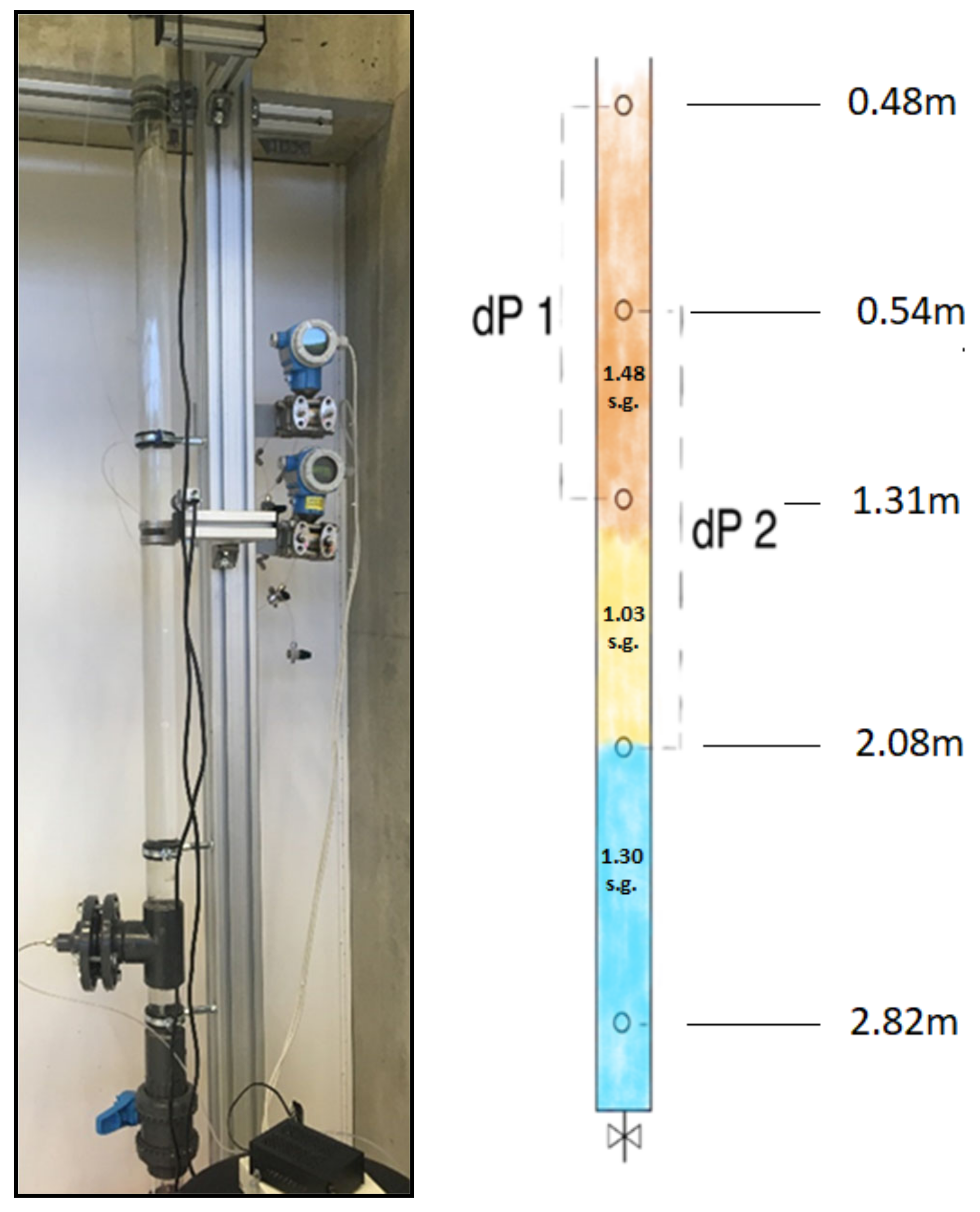
2.5. Equipment and Test Setup

The gel pill has a density of 1.03 s.g. A 1.30 s.g. viscosified brine was placed beneath this pill. Finally, a water-based drilling fluid with a density of 1.48 s.g. was placed on top of the gel pill. Figure 7 shows a picture of the test column and a sketch of the interfaces placed between the fluids, and their measurement points. The drilling fluid was designed so that its barite particles would settle out of the fluid during a period of approximately one hour after placement. Table 4 shows the mix designs and mixing order of the fluids.
A laboratory scale test setup made of transparent acrylic pipe is shown in Figure 7. The length of the pipe was 3.8 m and the pipe inner diameter was 49.7 mm. The setup was connected to a digital pressure gauge that read the pressure at the base of pipe. There were four penetrations with differential pressure probes to measure the changes in differential pressure, as indicated on the drawing in Figure 7. The four points in the center of tube indicate the differential pressure measurement points. At the bottom, there was a fifth penetration where the bottom hole pressure was measured. The setup was designed with the possibility of changing the inclination from vertical to 40 degree from vertical. The setup was equipped with two cameras to record the drilling fluid–gel pill and gel pill–brine interfaces.
In performing the test, the following procedure was used: first, the viscosified brine volume was placed in the test equipment. Normally, air bubbles must be removed. This was done by vibrating the experimental setup. Thereafter, the gel pill was placed on top of the brine. To place the gel pill, a custom-made hand pump with a volume of 1.5 L was used. Due to volumes of the workstring and the length of gel pill, refilling of the pump was necessary. When the gel pill was placed, a sponge pig was run to clean the pipe, which compressed the gel pill gently. The gel was left to rest for at least 30 min prior to placing the model drilling fluid on top of the gel pill. The gel placement was a pump and pull operation. Subsequently, the prepared amount of water base drilling fluid (WBDF) was placed on top of the gel pill and the remaining upper section of the setup filled with tap water. After some time, barite particles started to settle out. The pressure transducers and the cameras recorded the settling phenomenon and the performance of the gel pill. An example of the recorded pressure during placement of the different fluid and pill volumes is shown in Figure 8. Note that the zero values of the differential pressure transducers are arbitrary. Initially, for each test, the tubes to the measurement probes were air filled. Later in the tests, these tubes became partly liquid filled. Therefore, the absolute values of the differential pressure measurements are uncertain. However, all changes after placement of all the fluid volumes were measured accurately. Therefore, only the relative value changes were used from this time onward.

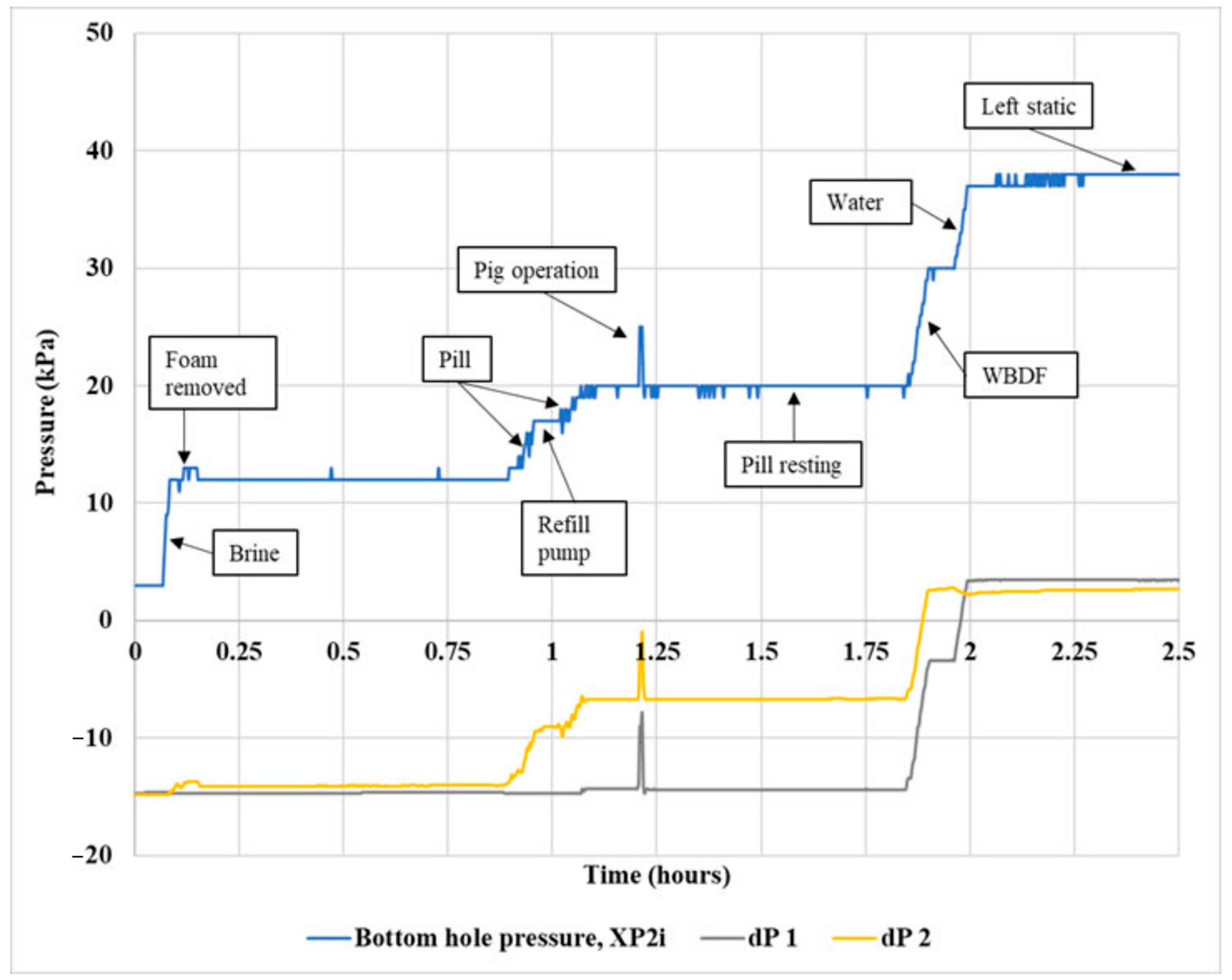
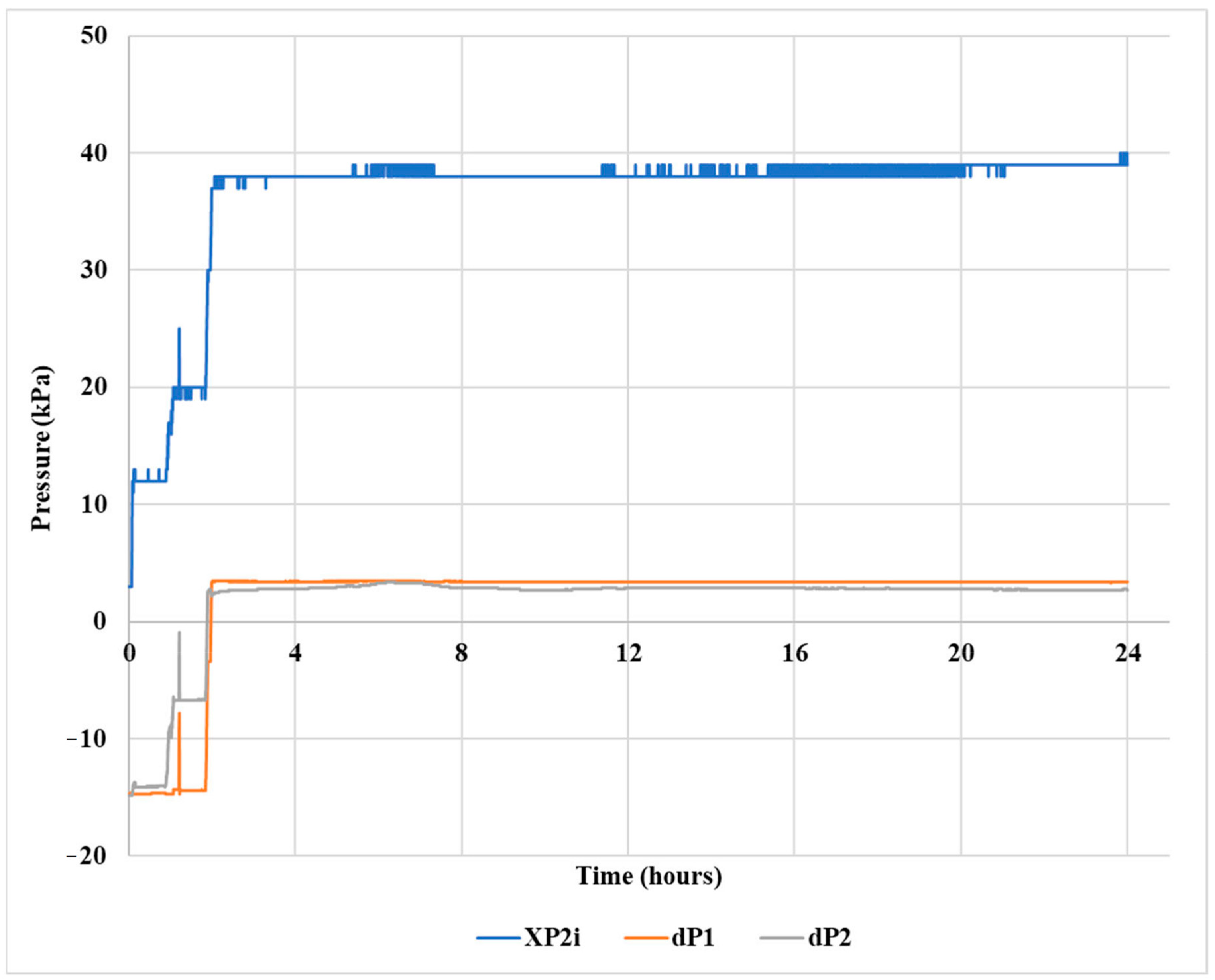
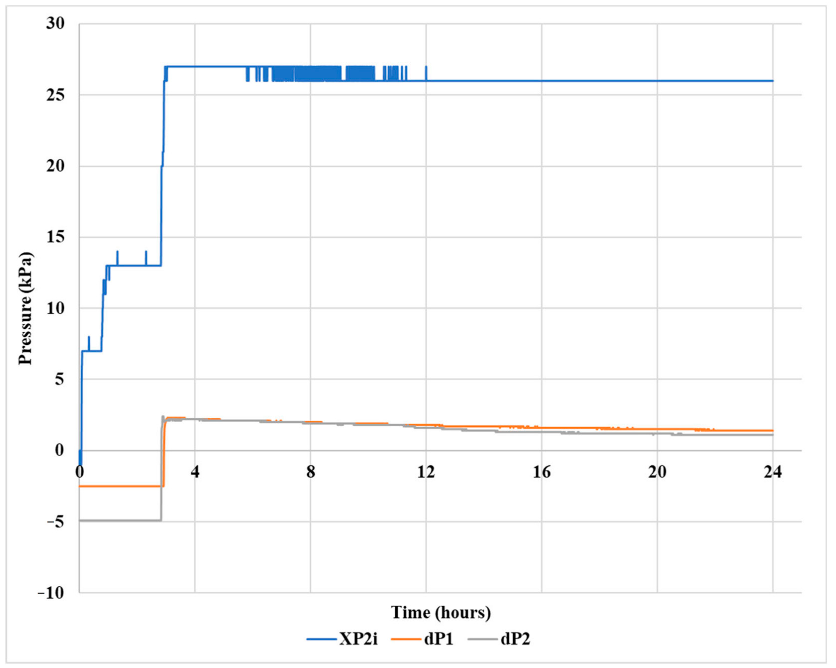
2.6. Gel Pill Performance in Vertical Hole

The experiment was conducted using the bentonite gel pill. Barite sag would occur in a static, vertical fluid column, the so-called static sag. Such a process is slow when the low shear viscosity is high, like in the present case. During the experiment, the concentration of barite particles should increase at the lower part of the tube filled with the model drilling fluid and decrease in the higher parts. By studying the pressure curves shown in Figure 9, the likely sag scenario is as follows. During the first two hours after placement of the drilling fluid volume, barite from the drilling fluid above the upper pressure sensor port sagged into the central parts of the drilling fluid column. Hence, the density increased and so did the pressure difference between the two upper measurement points. Thereafter, the density was reduced slowly. Twenty hours after placement of the drilling fluid volume, the pressure difference was back to the original. This required that some of the barite at that moment had been able to sag out of the column above the second pressure port of the pressure cell dP1. The pressure was anticipated to slowly decrease further until all barite was settled out.
The pressure readings from the dP2 differential pressure probe were constant during the first 20 h after placement of the drilling fluid. Any barite settled on the gel pill was not determined until the amount of settled barite was sufficient to either deform or move the gel pill. Most likely, the effect of sag in this part of the column was balanced by barite settling into the column and equal to the barite settling onto the gel.
In broad scale, the performance using the laponite pill (Figure 10) was similar to that of the bentonite pill (Figure 9). Some sagging from the upper drilling fluid volume part was observed in the first two hours after placement of the drilling fluid as the dP1 values increased slightly. Then in the following period, more barite was sagging out of the measurement zone than into this zone. No explanation can be verified for the increased drilling fluid density for the volume between the dP1 ports during the last 7 h. The pressure from the dP2 sensor showed reasonably constant values throughout the whole experiment. This indicates that the laponite pill retained its position throughout the total experimental time. The lack of movement of the gel pill was verified by the photographs showing the same position both before and after the 20 h static period, as shown in Figure 11.

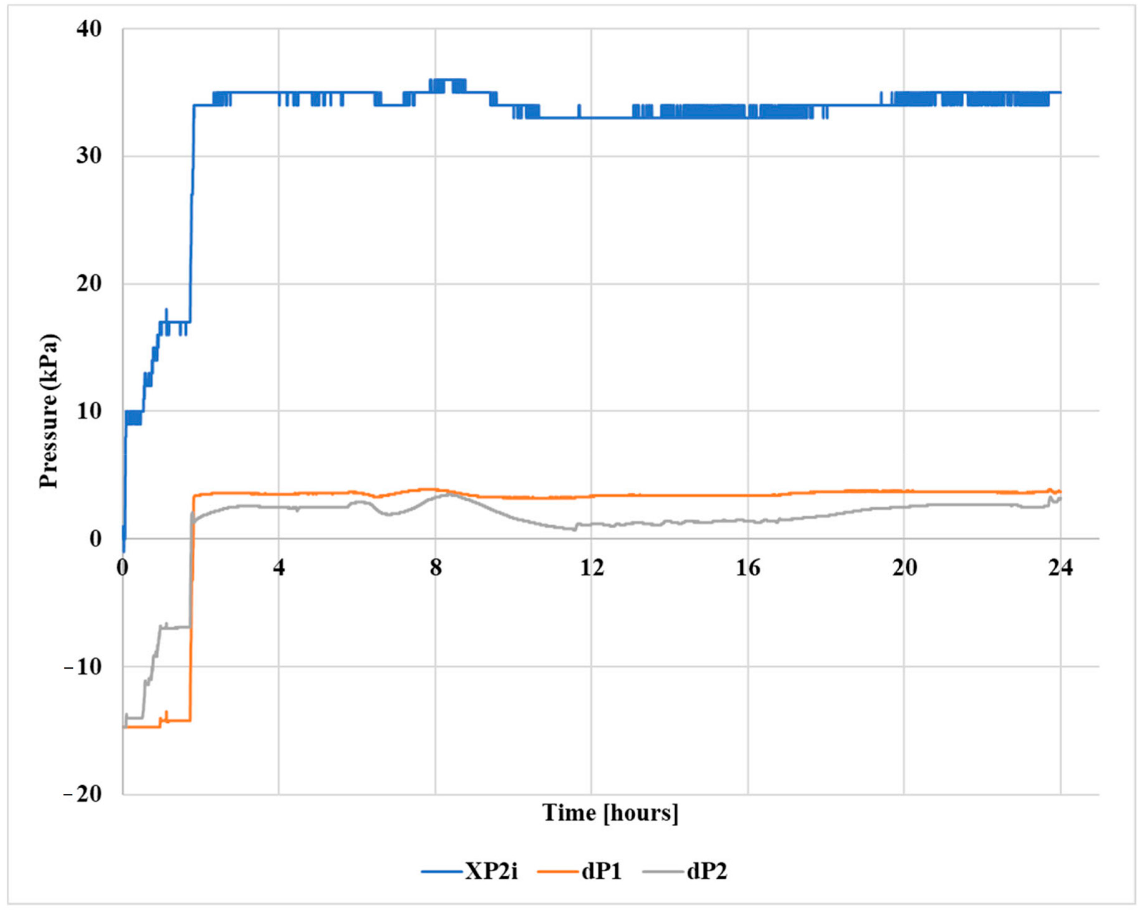
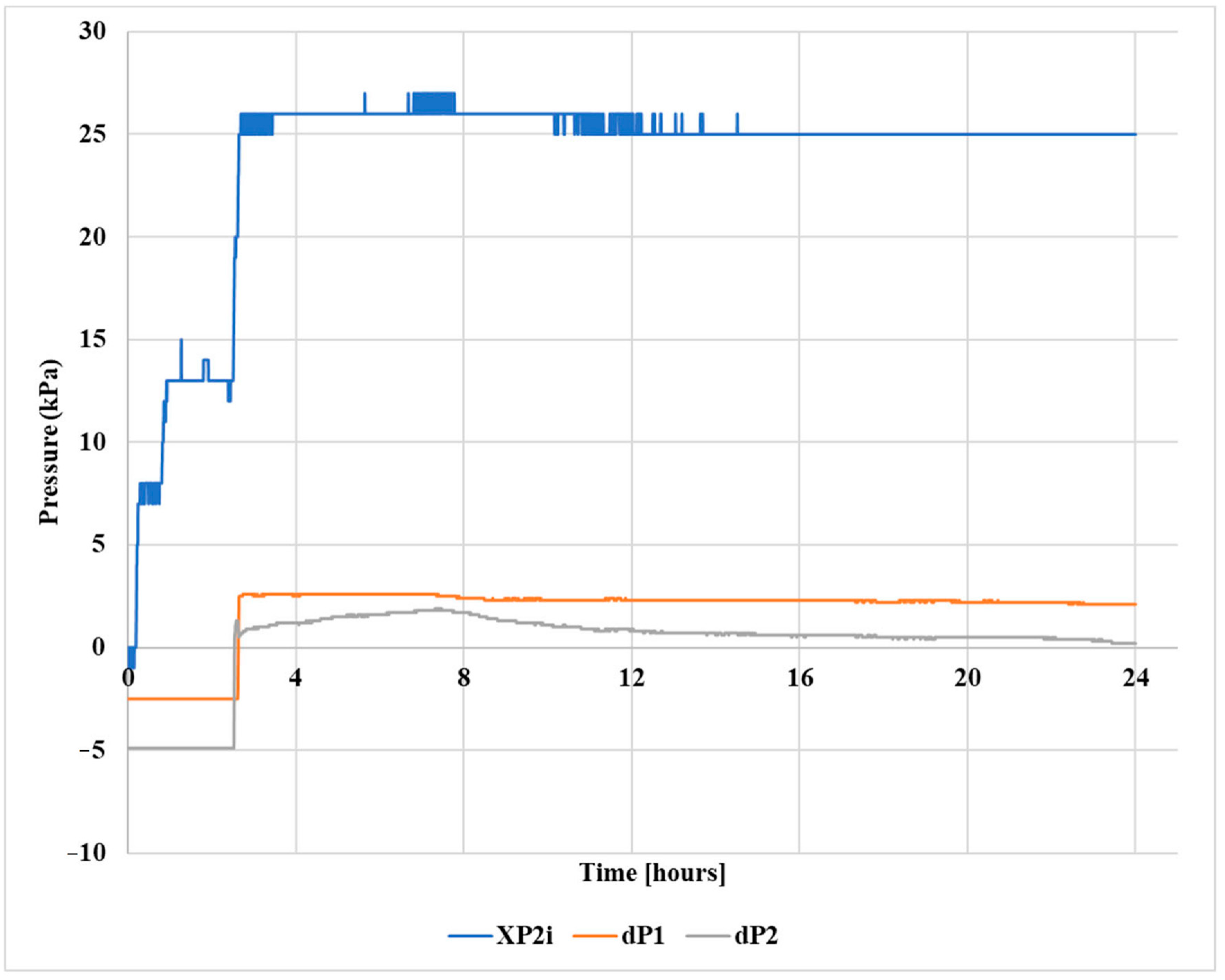
2.7. Gel Pill Performance in a 40° Deviated Hole

The tendency of sag is stronger in deviated holes than in vertical holes because of the Boycott effect [5]. The barite sag direction is now also in the cross-sectional direction, creating density differences in the cross section. Hence, there is a density difference in the cross section that sets up a fluid circulation accelerating the sag. This is clearly seen in the gel pill experiments at a 40° angle from vertical. The pressure measurements from the bentonite test are shown in Figure 12 and from the laponite test in Figure 13. In both tests, the dP1 sensor registered a significant reduction in pressure, indicating that barite was sagging out of the fluid column between the sensor ports. At the same time, the dP2 sensor measured less reduction in pressure than was measured using the dP1 sensor. This means that the weight of the sagged material falling onto the gel was unable to produce a force large enough to be transmitted to the bottom of the gel. This was also indicated by the lack of change in bottom hole pressure. A small reduction was measured. However, this was less than any of the pressure reductions measured by the dP1 or dP2 sensors. Hence, the gel was strong enough to withstand the change in pressure from the top.
Photos of the interfaces between the laponite gel and the drilling fluid or viscosified brine are shown in Figure 14. The photos were recorded just after placement and 24 h later. The positions of the interfaces remain unchanged, verifying the analysis of the results from the data shown in Figure 13.

3. Discussion and Remarks

So-called viscous pills have been used extensively in the petroleum industry to prevent intermixing of a dense well fluid placed above a lighter fluid. The success rate has varied. The industry has not had a proper definition of the term viscous pill. Hence, viscous pill has been used for a large variety of limited well fluid volumes pumped into a well. In this work, the term viscous pill has been defined as a high viscosity material without any significant gel formation. If gel formation has been significant, then the term gel pill has been used. Based on the measurement and analysis in the previous section, use of a purely viscous pill cannot hinder intermixing of a high density fluid placed above a lighter fluid. This should therefore not be applied in practical operations.
Two bentonite-type-based gel pill systems were found to be efficient in hindering intermixing of a denser fluid placed above a lighter fluid. These fluids create a good gel structure with bonding to the surface. The analysis did not focus on finding the limit of the yield stress or gel formation required to maintain the desired function. An analysis can be performed based on Equation (1), presenting the necessary gel strength. However, the gel strength measurements that can be obtained following industrial standards recommend methods incapable of measuring the strength of a gelled particle network.
Both the successful gel systems presented in this work are particle gels. Earlier, a crosslinked polymer gel system provided similar effect, as shown by Ronæs et al. [25]. In this case, the gel did not bond to hole walls. Hence, they transmitted pressure from the overlaying fluid column independent of the magnitude of the added pressure. For the current gel pill system, this transmission is not expected until a pressure difference given by Equation (1) is obtained. As can be seen from the measurements shown in Figure 12, there is a significant pressure reduction in the region measured using differential pressure transducer number two, which includes the pressure drop over the gel pill. This pressure reduction was not observed by using the bottom hole pressure sensor. Hence, the gel pill was anticipated to trap the down hole pressure until the pressure difference over the gel pill exceeded the maximum pressure it could hold. Then, the gel would move slightly and re-establish pressure control.
During the time of the experiments, the pressure measurements dP1 and dP2 both demonstrated reduction in the differential pressure, resulting from settling of barite. Barite settled onto the gel pill surface without creating any changes in the down hole pressure. In addition to trapping the pressure because of the gel forces, the weight of the settled barite must also be lifted before the gelled pill moves in any direction. It is not yet known how the pressure will change if the barite occupies the whole pipe volume. In this case, it may be possible that the settled barite transfers parts of its weight to the tubing.

4. Conclusions

Viscous and gel pills for allowing placement of a denser fluid above a lighter fluid have been analyzed. The conclusions are:
  • A purely viscous pill should not be used for separating a high density fluid from a lighter fluid underneath.
  • A bentonite or laponite gel, can be placed in a well for temporary prevention of intermixing of the fluids above and underneath the gel pill.
  • Both the bentonite and laponite gel pills function as a good collection bed for settled barite.

Author Contributions

The article is a summary of L.P.’s MSc Thesis performed with professors M.K. and A.S. as supervisors. Other authors represent the steering committee of the project. The steering committee was active in deciding the direction of the project and the experiments. All authors have contributed with text additions. All authors have read and agreed to the published version of the manuscript.

Funding

The project was supported by Equinor.

Acknowledgments

The authors would like to thank Kjell Morten Sviland for his help and contributions to this work.

Conflicts of Interest

The project had no commercial elements. For this manuscript, there are no potential conflicts of interest.

References

  1. Ofei, T.N.; Kalaga, D.V.; Lund, B.; Saasen, A.; Linga, H.; Sangesland, S.; Gyland, K.R.; Kawaji, M. Laboratory Evaluation of Static and Dynamic Sag in Oil-Based Drilling Fluids. SPE J. 1995. SPE-199567-PA. [Google Scholar] [CrossRef]
  2. Omland, T.H.; Albertsen, T.; Taugbol, K.; Saasen, A.; Svanes, K.; Amundsen, P.A. The Effect of the Synthetic- and Oil-Based Drilling Fluid’s Internal Water-Phase Composition on Barite Sag. SPE Drill. Complet. 2006, 21, 91–98. [Google Scholar] [CrossRef]
  3. Omland, T.H.; Saasen, A.; Van Der Zwaag, C.; Amundsen, P.A. The Effect of Weighting Material Sag on Drilling Operation Efficiency. In Proceedings of the SPE Asia Pacific Oil and Gas Conference and Exhibition, Jakarta, Indonesia, 30 October–1 November 2007. [Google Scholar]
  4. Saasen, A.; Liu, D.; Marken, C. Prediction of Barite Sag Potential of Drilling Fluids From Rheological Measurements. In Proceedings of the SPE/IADC Drilling Conference, Amsterdam, The Netherlands, 28 February–2 March 1995. [Google Scholar]
  5. Boycott, A.E. Sedimentation of Blood Corpuscles. Nat. Cell Biol. 1920, 104, 532. [Google Scholar] [CrossRef]
  6. Palma, S.; Ihle, C.F.; Tamburrino, A. Characterization of a sediment layer of concentrated fluid-solid mixtures in tilted ducts at low Reynolds numbers. Powder Technol. 2018, 325, 192–201. [Google Scholar] [CrossRef]
  7. Movahedi, H.; Shad, S.; Mokhtari-Hosseini, Z.B. Modeling and simulation of barite deposition in an annulus space of a well using CFD. J. Pet. Sci. Eng. 2018, 161, 476–496. [Google Scholar] [CrossRef]
  8. Nguyen, T.; Miska, S.; Yu, M.; Takach, N.; Ahmed, R.; Saasen, A.; Omland, T.H.; Maxey, J. Experimental study of dynamic barite sag in oil-based drilling fluids using a modified rotational viscometer and a flow loop. J. Pet. Sci. Eng. 2011, 78, 160–165. [Google Scholar] [CrossRef]
  9. Kynch, G.J. A theory of sedimentation. Trans. Faraday Soc. 1952, 48, 166–176. [Google Scholar] [CrossRef]
  10. Taylor, G.I. The instability of liquid surfaces when accelerated in a direction perpendicular to their planes. Proc. Lond. Math. Soc. A 1950, 201, 192–196. [Google Scholar]
  11. Saasen, A.; Tyvand, P.A. Rayleigh-Taylor instability and Rayleigh-type waves on a Maxwell-fluid. J. Appl. Math. Phys. ZAMP 1990, 41, 284–292. [Google Scholar] [CrossRef]
  12. Sharma, R.C. Rayleigh-taylor instability of two viscoelastic superposed fluids. Acta Phys. Acad. Sci. Hung. 1978, 45, 213–220. [Google Scholar] [CrossRef]
  13. Harestad, K.; Herigstad, T.P.; Torsvoll, A.; Nodland, N.E.; Saasen, A. Optimization of Balanced-Plug Cementing. SPE Drill. Complet. 1997, 12, 168–173. [Google Scholar] [CrossRef]
  14. Dickinson, E. An Introduction to Food Colloids; Oxford University Press: Oxford, UK, 1992; ISBN 0198552238. [Google Scholar]
  15. Fosso, S.W.; Tina, M.; Frigaard, I.; Crawshaw, J. Viscous-Pill Design Methodology Leads to Increased Cement Plug Success Rates; Application and Case Studies from Southern Algeria. IADC SPE Asia Pac. Drill. Technol. 2000. [Google Scholar] [CrossRef]
  16. Saasen, A.; Ytrehus, J.D. Viscosity Models for Drilling Fluids—Herschel-Bulkley Parameters and Their Use. Energies 2020, 13, 5271. [Google Scholar] [CrossRef]
  17. Christidis, G.E.; Aldana, C.; Chryssikos, G.D.; Gionis, V.; Kalo, H.; Stöter, M.; Breu, J.; Robert, J.-L. The Nature of Laponite: Pure Hectorite or a Mixture of Different Trioctahedral Phases? Minerals 2018, 8, 314. [Google Scholar] [CrossRef] [Green Version]
  18. Huang, W.; Leong, Y.-K.; Chen, T.; Au, P.-I.; Liu, X.; Qiu, Z. Surface chemistry and rheological properties of API bentonite drilling fluid: pH effect, yield stress, zeta potential and ageing behaviour. J. Pet. Sci. Eng. 2016, 146, 561–569. [Google Scholar] [CrossRef] [Green Version]
  19. American Petroleum Institute. Recommended Practice for Testing Oil-based Drilling Fluids; API: Washington, DC, USA, 2014; API Recommended Practice 13B2. [Google Scholar]
  20. Pek-Ing, A.; Yee-Kwong, L. Surface chemistry and rheology of Laponite dispersions—Zeta potential, yield stress, ageing, fractal dimension and pyrophosphate. Appl. Clay Sci. 2015, 107, 36–45. [Google Scholar] [CrossRef]
  21. Zamora, M.; Power, D. Making a case for AADE hydraulics and the unified rheological model. In Proceedings of the AADE 2002 Technology Conference, Houston, TX, USA, 2–3 April 2002. [Google Scholar]
  22. Power, D.; Zamora, M. Drilling Fluid Yield Stress: Measurement Techniques for Improved Understanding of Critical Drilling Fluid Parameters. In Proceedings of the AADE 2003 National Technology Conference, Houston, TX, USA, 1–3 April 2003. [Google Scholar]
  23. Petroleum and Natural Gas Industries. Field Testing of Drilling Fluids. Part 1: Water-Based Fluids; International Organization for Standardization: Geneva, Switzerland, 2008; Report ISO 10414-1. [Google Scholar]
  24. Petroleum and Natural Gas Industries. Field Testing of Drilling Fluids. Part 2: Oil-Based Fluids; International Organization for Standardization: Geneva, Switzerland, 2001; Report ISO 10414-2. [Google Scholar]
  25. Ronaes, E.; Prebensen, O.I.; Mikalsen, R.; Taugbol, K.; Syltoy, S.; Torvund, S. An Innovative Fluid Pressure Transmission Pill Successfully Used During Managed-Pressure Drilling Operations in an HTHP Environment. In Proceedings of the IADC/SPE Drilling Conference, Orlando, FL, USA, 4–6 March 2008. [Google Scholar]
Figure 1. Settling in a well. (a) Settling in a vertical section. (b) Boycott settling.
Energies 13 06318 g001
Figure 2. Flow curve of the model drilling fluid.
Energies 13 06318 g002
Figure 3. Flow curves of the viscous pills prior to experiments. Stippled line with triangles represents Pill 1 and solid line with diamonds represents Pill 2.
Energies 13 06318 g003
Figure 4. Illustration of the benchtop experiments and the result of the test with viscous Pill 2.
Energies 13 06318 g004
Figure 5. Flow curve of an investigated bentonite gel pill (solid blue line) and the laponite gel pill (dotted red line).
Energies 13 06318 g005
Figure 6. Flow curve of the viscosified brine.
Energies 13 06318 g006
Figure 7. Laboratory experimental equipment. Picture of the tiltable tube to the left, and the experimental design drawing to the right. The position measurements refer to distance from the top.
Energies 13 06318 g007
Figure 8. Recorded pressure during placement of fluid volumes. The bottom hole pressure is shown as the blue line. The differential pressures dP1 and dP2 are shown as the orange and gray lines, respectively. The zero pressure is valid for the bottom hole pressure only (blue curve). For the dP-sensors, the zero level is arbitrary.
Energies 13 06318 g008
Figure 9. Recorded pressure during an experiment in a vertical fluid column using the bentonite gel pill. The bottom hole pressure is shown as the blue line. The differential pressures dP1 and dP2 are shown as the orange and gray lines, respectively.
Energies 13 06318 g009
Figure 10. Recorded pressure during an experiment in a vertical fluid column using the laponite gel pill. The bottom hole pressure is shown as the blue line. The differential pressures dP1 and dP2 are shown as the orange and gray lines, respectively.
Energies 13 06318 g010
Figure 11. Picture of the laponite gel pill and model drilling fluid interface (upper picture), and brine and gel pill interface (bottom) for the vertical tests, (a) initially and (b) after 24 h.
Energies 13 06318 g011aEnergies 13 06318 g011b
Figure 12. Recorded pressure during an experiment in a column deviated 40° from vertical using the bentonite gel pill. The bottom hole pressure is shown as the blue line. The differential pressures dP1 and dP2 are shown as the orange and gray lines, respectively.
Energies 13 06318 g012
Figure 13. Recorded pressure during an experiment in a column deviated 40° from vertical using the laponite gel pill. The bottom hole pressure is shown as the blue line. The differential pressures dP1 and dP2 are shown as the orange and gray lines, respectively.
Energies 13 06318 g013
Figure 14. Picture of the laponite gel pill and model drilling fluid interface (upper picture), and brine and gel pill interface (bottom) at the 40° deviation tests, (a) initially and (b) after 24 h.
Energies 13 06318 g014
Table 1. Mix design and mixing procedure for the model drilling fluid.
IngredientsQuantity (g)Mixing Time (min)
Tap water249NA
Xanthan biopolymer0.320
Xanthan concentration (g/L)1.2
Barite18530
Table 2. Mix design and mixing procedure for the viscous pills.
IngredientsPill 1 (g)Pill 2 (g)
Tap water350350
Xanthan biopolymer3.04.0
Xanthan concentration (g/L)8.611.4
Table 3. Mix design and mixing procedure for the bentonite pill.
IngredientsQuantity (g)Mixing Time (min)
Tap water343NA
NaCO30.027
NaOH1.03
Bentonite2065 *
NA: Not Applicable. * Mix for 5 min, left to rest for 30 min, and then mixed for 60 min.
Table 4. Mix design and mixing procedure for the laponite pill.
IngredientsQuantity (g)Mixing Time (min)
Tap water343NA
NaCO30.027
NaOH1.03
Laponite RD1265 *
NA: Not Applicable. * Mix for 5 min, left to rest for 30 min, and then mixed for 60 min.
Table 5. The yield stress measured in accordance with Zamora and Power [21,22], and gel strength measured in accordance with oilfield standards [19,23,24] for the bentonite and laponite system.
Shear Stress (Pa)BentoniteLaponite
Yield stress33.125.4
10 s gel strength25.720.2
10 min gel strength35.159.9
Table 6. Mix design and mixing procedure for the viscosified brine.
IngredientsQuantity (g)Mixing Time (min)
Tap water249NA
Xanthan Gum0.18115
CaCl2*2H2O113.630
Publisher’s Note: MDPI stays neutral with regard to jurisdictional claims in published maps and institutional affiliations.

