1. Introduction
The lifetime of the roller cone bit or the time of effective drilling operations depends on the properties of the materials from which the components of the roller cone bit are made. The roller cone bit becomes worn because of the effects of the rock material through which it is drilled and the drilling regime. Owing to the wear of the bit, the penetration rate decreases.
The effective operation of the bit depends on its resistance to the factors that occur during its operation. Among the factors that have a significant impact on the effective operation of the roller cone bit, we can include the following: the steel material from which the rollers and the teeth of the bit are made, and the drilling parameters (load on the bit during drilling, torque, the number of bit rotations, and the amount and properties of the drilling fluid) in relation to the rock properties through which we drill.
We analyzed the mechanical properties of the steel material of the roller cone bit IADC 136, ∅155.57 mm (6 1/8"), which drilled through carbonate siltstone, in which sandstone sheets appear as well as rare thin layers of clay and limestone with a total length of 87.89 m.
In our research, we focused on the resistance of the steel material of the roller cone bit to the rock material.
To this end, it was necessary to identify, with scientific approaches, the causes that lead to the wear of the bit, in order to study the mechanism of flow of the drilling fluid around the rollers of the bit, which is mixed with the particles of the rock material, and to determine the weak spots on the bit that need to be technologically changed in the sense of prolonging the time of effective drilling. Extending the bit life and related efficient drilling cannot be done simply by changing one parameter, e.g., hard steel cover or tooth material itself, rather it is necessary to change and study each parameter separately for efficient drilling to achieve optimum progress.
The research on the influence of friction on the teeth material of the bit and on its stability [
1,
2] indicates the direction of the development of nanomaterials or nanostructured coatings, which have a low coefficient of friction and high strength and hardness, which extends the lifespan of the roller cone bit.
A number of researchers have engaged lately with the mechanism of the operation of the roller cone bit teeth to the rock material. By optimizing the shape of the teeth, the optimum rock fracture can be achieved [
3,
4,
5]. The shape of the teeth, the tooth material, and the size and arrangement of the teeth on the roller cone bit must be adapted to the rock material being drilled.
The rate of penetration of the bit through the rock material as a function of the drilling regime was studied by several authors [
6,
7,
8,
9,
10,
11]. The influence of drilling parameters—drilling regime—such as load on the bit, number of rotations, momentum, and penetration rate of the bit into the rock, were examined.
The result of wear of the cutting mechanism on the tooth of the bit, shows that the cutting effect is greatly reduced and the geometry of the tooth of the bit is changed; therefore, a reduction in the penetration rate occurred [
12,
13,
14,
15,
16,
17,
18,
19,
20,
21,
22,
23].
An analysis of influence factors on increasing temperature during drilling on the drill bit was established by bit geometry and drilling parameters, as well as the strength and the stress state of the rock [
24].
The influence of solid particles in the suspension (drilling fluid) on the erosion of steel surfaces, and consequently the loss of material and its fatigue, is significant [
25,
26,
27,
28]. The result of the erosion is loss of the steel material of the tooth. The consequence of this loss is the reduction and change in the geometry of the teeth of the roller cone bit. Because of this change in the geometry, the teeth have reduced efficiency in terms of breaking of the rock material.
An increased presence of vibrations has a considerable impact on the wear of the roller bearings. This problem has been studied by previous researchers [
29,
30]. In drilling technology, the usual failure of bearings depends on the following causes: vibrations of the rods during drilling, the quality of the bearing sealing, the effective lubrication of the bearings, and the quality of the bearing itself.
2. The Roller Cone Drill Bit Operation Principle
The roller cone bit contains cutting elements, i.e., teeth or inserts, which are mounted on the rollers. The rollers, which are inserted into the bearings of the bit, rotate around their axis. They are driven by the rotation of the drillstring, which drives the body of the drill bit on which the roller is mounted. Nozzles are installed on the bit body to effectively remove the rock particles from the bottom of the well and cool the bit rollers and tooth. Through the nozzles, the drilling fluid flows out from the interior of the drill rod into the bit area. Because of the reduction of the aperture represented by the ratio of the cross section of the drill bit to the cross section of the nozzles, the velocity of the outflow of the drilling fluid increases greatly, which favorably influences the flow of the outflow around the rolls, effectively removing the drilled rock particles from the borehole and, especially in the softer poorly bonded rocks, contributing to its breaking.
The roller cone bit with steel teeth, which is the subject of study in this work, is used in softer, poorly bonded rock formations. Teeth on the rollers are large and sharp, so they can penetrate deeply into the soft rock structures where the rock is crushed and the drilled material is removed from the crushed area. In order to improve persistence and thereby prolong the effective operating time, the teeth are protected with a carbide coating. The axles of the rollers do not intersect at the point of the central axis of the bit, but have an offset according to the point of the central axis of the bit. This is usually in the range from 2° to 5°.
Through years of development of roller cone bits, several researchers explained the interrelation effect between the rock and the bit through their research. In particular, the research represented the relationship between drilling parameters and the construction of the roller cone bit. The earlier model of this correlation was presented by Galle and Woods [
31], and later by Morlan [
32]. Their research concerned the presentation of the rate of penetration (ROP) in softer formations in the function of weight on bit (WOB) and the number of rotations (RPM). Maurer [
33,
34] proposed his model as a function between the drilling regime and rock strength. The disadvantage of this model is that it has a poor estimation of the penetration rate at low loads on the bit. Bingham [
35] proposed a new model for determining the penetration rate, based on a small number of laboratory data and on the estimation that, with a negligible load on the bit, the rotation of the bit progresses despite the fact that the penetration rate decreases when the rotation speed of the bit is increased. A few years later, Bourgoyne and Young [
36] proposed a model for determining the penetration rate, which took into account several drilling parameters. This model was suitable for determining the penetration rate of milled tooth roller cone bits whose rollers’ bearings are not sealed and the borehole is vertical. The drilling parameters that this model takes into account relate to the load on the bit, the number of rotations, and wear of teeth, and the rest as variables that are not dependent on one another. Warren [
37,
38] presents his model of determining the penetration rate, which takes into account the effects of the mechanical and lithological characteristics of the rock through which we drill. The model was developed using dimensional analysis, giving the corresponding curves that best match the data obtained in the laboratory. The results of this model show that the volume of the rock, which is chipped with one tooth of the roller bit, is disproportionate to the square of the load on the tooth and is inversely proportional to the square of the rock strength. Rampersad et al. [
39] transformed Warren’s [
37,
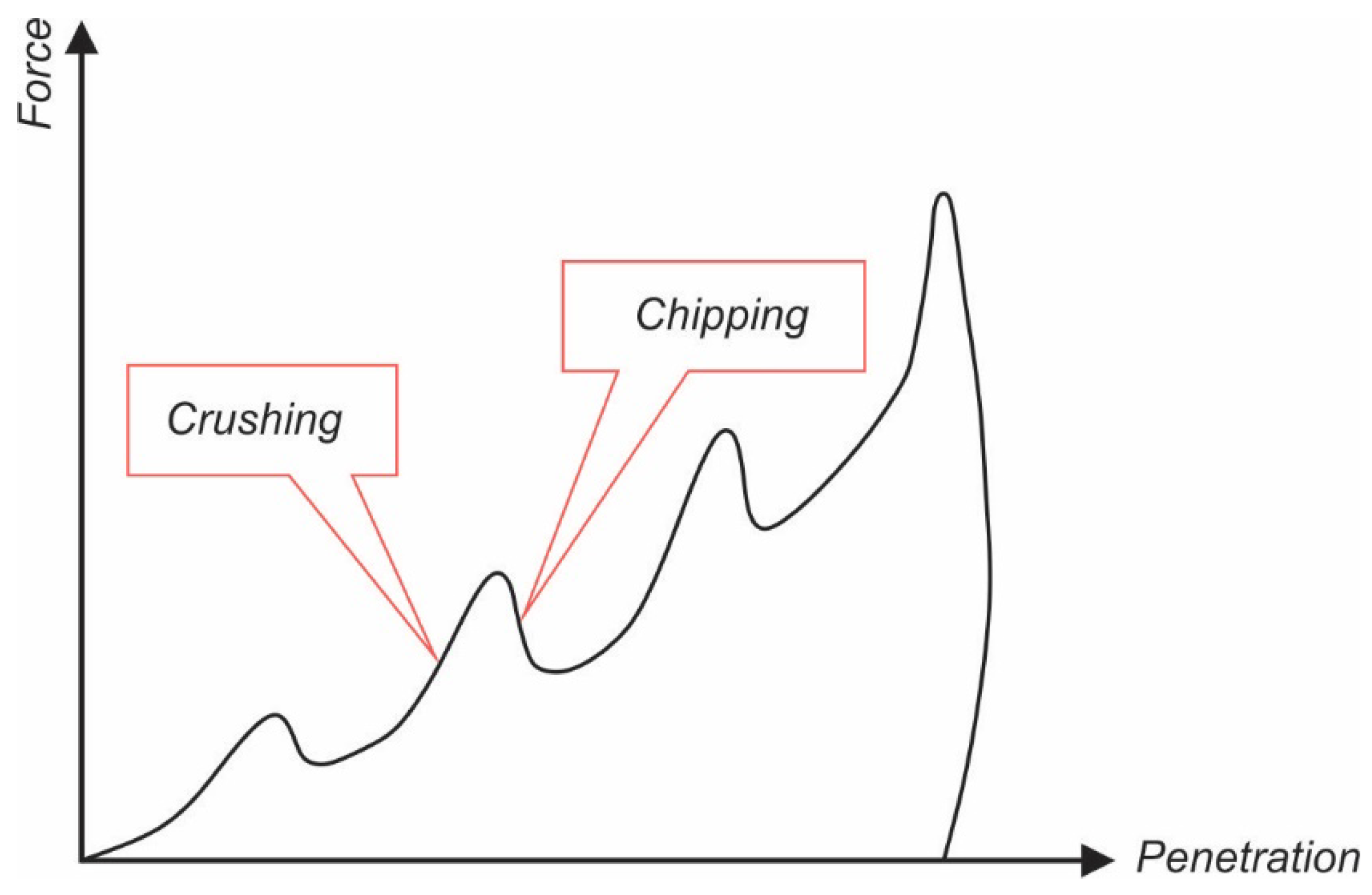
38] model by taking into account the wear of the tooth and the effect of the wedging on the part of the particles in the crater made by the tooth. In terms of the method of crushing and removing the material from the crushing site, Paul and Sikarskie [
40] presented a theoretical study for a static wedge penetration model based on the Mohr–Coulomb failure criterion. Their theory shows how the tooth of the roller cone bit progresses through the crushing and shipping stages of the rock, as shown in
Figure 1.
Positive slopes show elastic deformations or collapse, while negative slopes show crushing.
Figure 1 shows the duration of one rolling cycle of the roller. Dutta [
42] upgraded the theory of Paul and Sikarskie [
40] by clarifying the crushing mechanism as an instantaneous release or energy release that involves crushing and chipping. It has been shown that the principle of demolition of the rock can be understood as the destruction of a fragile material whose breakdown cracks are the result of the operation of the cutting tool. Cheatham [
43], in his study, found what load on the tooth (wedge) is needed to penetrate the rock. In his model, he assumed that the rock under the tooth is isotropic and homogeneous. This satisfied the boundaries of the Mohr–Coulomb failure criterion theory. The process of the demolition of the rock under the influence of a cutting tool—the tooth—contains the establishment of a tension state, the formation of an inelastic deformation zone, and the formation of a crater formed by a collapse wedge. The formation of the fragments of the rock resulting from the progression of the tooth into the rock is a continuous process that involves the destruction of the rock and its crushing. In the phase of crushing, the rock cracks in the area of the wedge formation. Under the influence of the progression of the tooth, tensions accumulate that lead to the fragmentation of the rock in the wedge area and, consequently, to exfoliate it from the crater. The wedge is formed along the collapse surface when a certain degree of penetration of the tooth into the rock is reached.
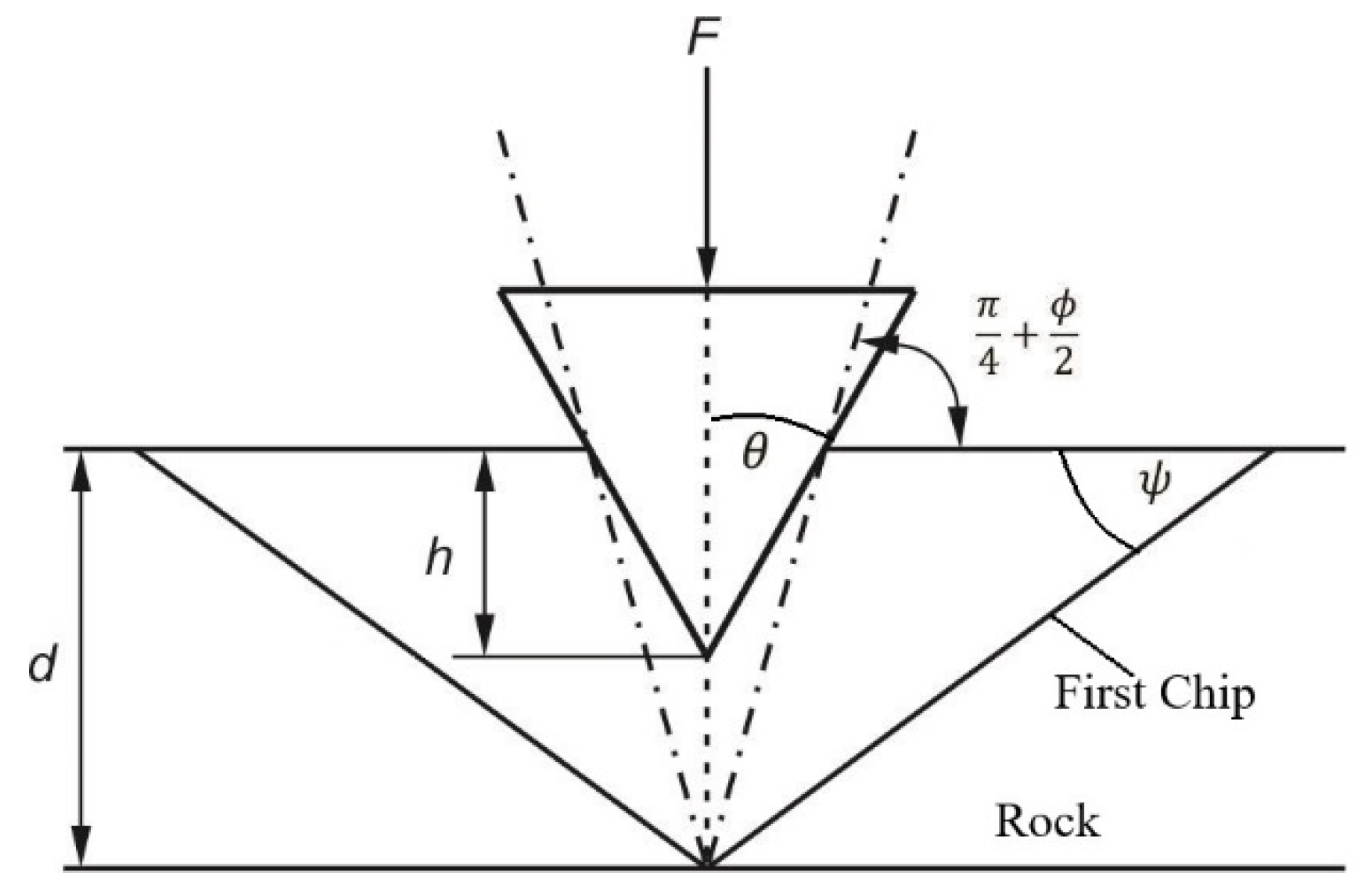
Figure 2 shows the formation of the (i + 1) wedge after wedge i was formed.
In theory, the shear stress along the line of fracture surface is proportional to the cohesive strength of the rock, which corresponds to Mohr–Coulomb failure criterion. The angle of the rock collapse
ψ, which is characteristic of a particular type of rock material, can be shown as a function of the angle of internal friction of rock
ϕ, as shown in Equation (1) and presented in
Figure 3.
Rashidi et al. [
41] developed a model for determining the rate of penetration of the roller bit based on the formation of a crater created by the individual tooth. The operation of each tooth of the bit consists of a crushing phase and a chipping of the rock, which illustrates the actual movement of the tooth on the roller of the bit.
The rock in the crater, which is removed directly by the action of the tooth, is the so-called plastic fragments of the rock, which are formed in the first stage. In the second phase or in the brittle phase, fragments of the rock are formed, which were chipped under the influence of vertical and lateral fragmentation, as shown in
Figure 4.
Experimental studies have shown that the load of an individual tooth on the rock formation is linearly proportional to the depth of the cut, the length of the wedge formed, and the rock strength [
44]. Further studies have shown that the load on one tooth can be expressed as a function of the projected surface of the tooth in contact with the rock, the penetration depth of the tooth, and the mechanical characteristics of the rock [
6].
The load on the tooth F, which causes the penetration (h) of the tooth into the rock, is a linear combination of force acting against the surface at the tip of the tooth and force acting against the surface formed by the angled surfaces of the tooth.
For the bits that have teeth on rollers made by the same material as the roller, we could state the following [
45]:
where
F is the load on a single tooth of the bit (N);
C1 is the coefficient of friction on the surface on the tooth tip (-);
w is the tooth width (m);
C2 is the coefficient of friction on the tooth surface, which is in contact with the rock (-);
h is the penetration depth of the tooth (m);
l is the tooth length (m); and
σp is the compressive strength of the rock (Pa).
The result of the reactive force
F on the tooth of the bit, which is in contact with the rock, is equal to the load generated on the bit [
41]:
where
WOB is weight on bit (N) and
nt is the number of teeth that are in contact with the rock.
The volume of the crater of the removed rock
Vcrat (m
3), which is created with one tooth, if we assume that the crater has a conical shape, is shown by the following equation [
41]:
where
rcrat is the crater radius (m) and
h is the crater depth (m).
Assuming that the shape and associated volume of the excavated rock crater are formed according the rock fracture surface, which is formed by the angle of rock collapse
ψ (°), we can state the collapse of the rock formed by the angle of the bursting rock as follows [
41]:
By following Equation (5), Equation (4) can be written as follows:
By determining the volume of an individual crater formed by an individual tooth, the rate of penetration can be evaluated, which is defined by the volume of the rock craters on the total cutting surface of the roller cone bit in number of turns [
41].
where
ROP is the rate of penetration (m/s),
Vcrat is the volume of the crater of the removed rock (m
3),
RPM is the number of rotations of the bit (s
−1), and
Abit is the cutting surface of the bit (m
2).
With the advancement in the rock, the teeth of the roller cone bit wear out. To determine the wear of the bit, we focused on the parameters that influence the penetration rate (ROP) of the roller cone bit. Bourgoyne and Young [
36,
46] defined these as influential parameters in Equation (8).
where
f1 is the effect of formation strength or rock durability,
f2 is the effect of formation depth,
f3 is the effect of formation compaction or pore pressure,
f4 is the effect of differential pressure,
f5 is the effect of bit diameter and bit weight,
f6 is the effect of rotary speed,
f7 is the effect of tooth wear, and
f8 is the effect of bit hydraulics.
We studied the wear of the roller cone bit, the appearance of damages and the change in the properties of the bit materials under the influence of the properties of the material through which it was drilled, the operational parameters (weight on bit, rotary speed, and so on), and the hydraulics of drilling fluid around the cones of the bit.
3. Materials and Methods
At the time of the investigations for the determination of the characterization of the roller cone bit wear, detailed investigations were carried out on the rock through which it was drilled, drilling parameters, and the materials from which the bit was made. To this end, we carried out an overview of the bit in the first phase, which included an overview of the condition of the bit after drilling through the rock layer according to the IADC bit dull evaluation method. In this part, we examined the state of the teeth and rollers of the rolling cone bit after drilling through familiar rock.
During drilling through known rock, the following drilling parameters were monitored:
The load on the bit;
The number of the bit rotations;
The quantity of the pumped drilling fluid;
The pressure of the pumped drilling fluid;
The properties of the drilling fluid;
The penetration rate;
The length of the drilled interval.
After the removal of the bit from the well and cleaning, a visual inspection of the bit was performed along with a characterization of wear and damage according to the IADC standards.
In our investigations, we examined the various properties of the materials of the drill bit. We studied their chemical compositions, defined micro and macro structures, thermodynamic characteristics, and mechanical properties.
We performed a complete analysis of the steel materials of the roller cone bit, which included the following examinations:
Chemical analysis of the components of the rollers and teeth with ICP (inductively coupled plasma) analyzer using ICP—OES Agillent 720;
Analysis of the micro and macro structure of roller cone bit materials with a reflected light microscope, the Olympus BX61 and the Olympus SZ61 stereo microscope with image analysis system Analysis 6.0;
The composition of the carbide coating of bit teeth with the XRF (X-ray fluorescence) method using a Thermo NITON XL3t XRF analyser;
A cross-sectional view of the bit teeth with a Jeol JSM 5610 scanning electron microscope (SEM) also using EDS analysis (energy-dispersive X-ray spectroscopy);
DSC (differential scanning calorimetry) of tooth steel and tooth carbide coating with NETZSCH STA 449 C Jupiter thermal analyser;
A dilatometric analysis of the tooth steel and the tooth carbide coating with low temperature dilatometer Bähr-Thermoanalyse GmbH DIL 801;
Vickers hardness tests of the teeth steel with a 100 g load with a microhardness tester Shimadzu type M.
The characteristics of the rock obtained by sampling were estimated based on the analysis by Rock Lab 1.0.
5. Discussion
While monitoring the operational parameters during drilling, it was determined that the roller cone bit was not loaded in accordance with the manufacturer’s recommendations, which recommend that the load on the bit is in range between 15 and 27 kN. The load on the bit during drilling was between 30 and 40 kN. Moreover, the number of bit rotations was too low, as they ranged from 35 to 45 rpm. The recommended number of rotations for this bit type is between 60 and 100 rpm.
It can be noted that the bit was overloaded with weight and the number of bit turns was too low.
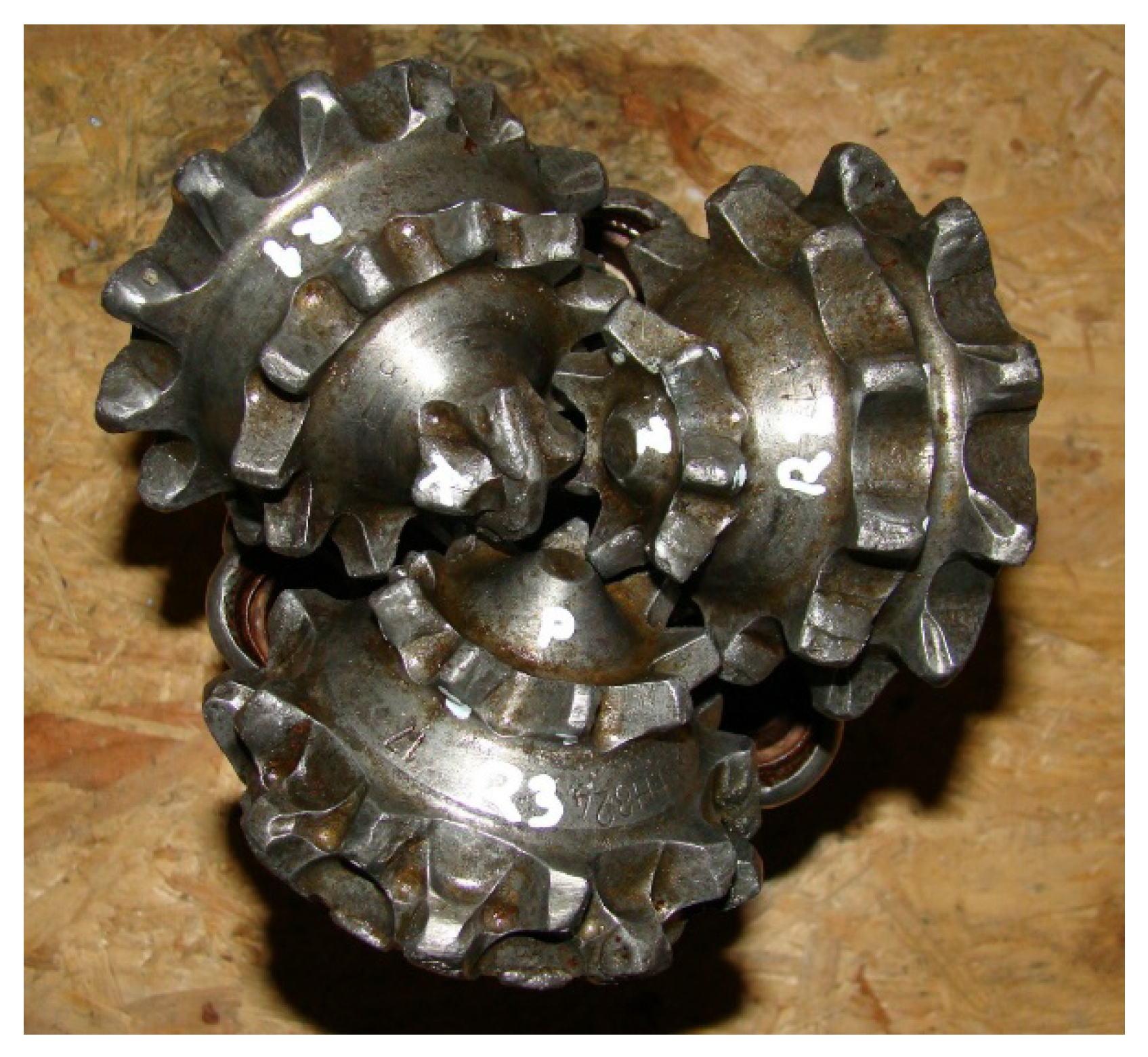
After cleaning, the damage of the bit was mainly reflected in the wear of the tooth tip (according to IADC: FC (flat crested wear)), which was expressed on all the teeth of the bit (
Figure 15). Some teeth were chipped (according to IADC: CT (chipped tooth)), and some were broken (according to IADC: BT (broken teeth)).
In the examination of the microscopic image, it was evident that the tops of the teeth were exposed to high temperatures and stresses. The influence of high temperatures and loads is shown in
Figure 16.
Figure 16 shows the tip of the tooth that was in contact with the rock. We can see changes in the color of the steel, which changes from top to bottom in shades of blue (at the point of contact between the rock and steel) to shades of brown, which changes the light from the top downwards.
Because of the apparent color change that was previously observed under the optical microscope, the sample was examined by a scanning electron microscope (SEM). A characteristic view of the microstructure of the area with an SEM is shown in
Figure 17.
Figure 17 shows the state of the tip of the tooth that was in contact with the rock during drilling. A change in the microstructure of the steel on the surface was observed. The change in the steel structure is noticeable in two layers. The first layer, where the change is noticeable, is up to a thickness of 36 µm. The second layer, where the change in the microstructure is less expressed, but still noticeable, moves to a depth of up to 92 µm.
The change in the steel microstructure of the tooth was due to the high temperatures and mechanical loads that occurred during drilling when the tip of the tooth was in contact with the rock. When turning the roller cone bit around on its axis, the teeth were cooled. The teeth, which are not in contact with the rock, were cooled by the drilling fluid that comes from the nozzles of the bit. In this situation, there is a temperature change on the surface of the teeth when their temperature is very high and they are washed by drilling fluid with a lower temperature. Another reason for microstructural changes in the steel can be found in the fact that the bit was overloaded during drilling and the number of turns was too low in relation to the load. The consequence of such a drilling regime is increasing temperature of the material at the top of the tooth, which, in connection with the load, has led to the hardening of the material at the tip of the teeth. For this reason, the hardness of the steel material increased. The measured hardness (according to Vickers) was, at this point, higher, on average, by approximately 160 HV than the hardness of the steel material in the center of the tooth.
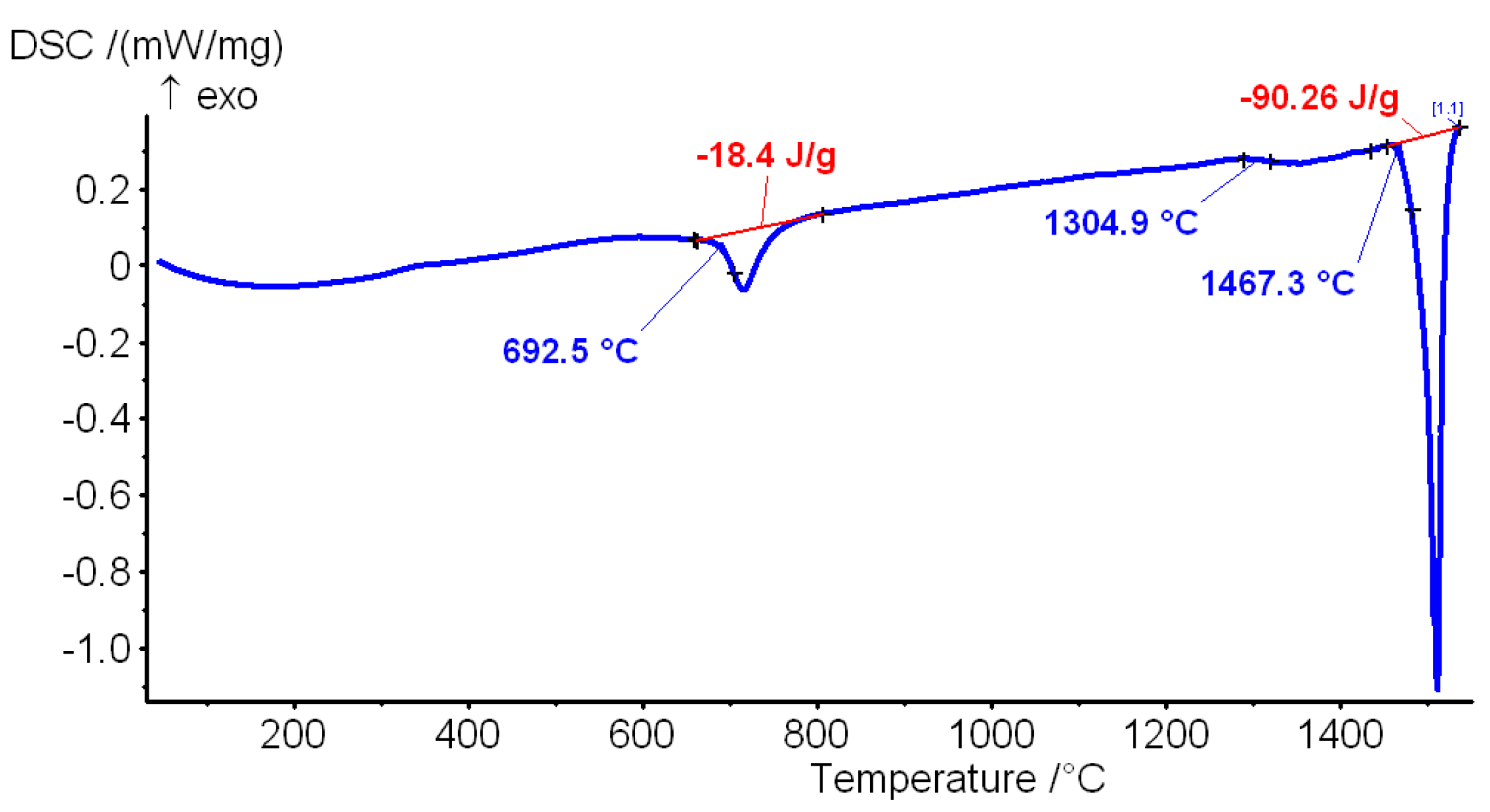
With differential scanning calorimetry (DSC), we found that the temperature of the eutectoid point is 699.2 °C or its completion at a temperature of 800 °C. Because of the intensive cooling of teeth under the influence of the drilling fluid, the microstructural change process proceeded only in the steel layer up to a depth of 92 µm. Microstructural changes are noticeable only at the top of the teeth, while at the sides, there were no changes observed.
The changes in steel microstructure occurred mainly as a result of excessive working temperatures and loads for the selected steel. As proved by DSC and dilatometric analysis, for the selected steel, the temperature at the start of the transformation from ferrite to austenite is approximately 680 °C. This means that the temperature of 680 °C (A
c1) represents a point where the recrystallization of steel accelerates rapidly. The recrystallization temperature for steel, if it is calculated for the information, is somewhere around 0.4 × T
L (T
L = liquidus temperature, °C) [
47]. Using the Thermo-Calc software, which is used for thermodynamic modeling of phase of equilibrium, we calculated the liquidus temperature, which was 1511 °C for the selected steel. Therefore, the temperature of the recrystallization for the analyzed steel is approximately 604 °C. We also calculated the equilibrium eutectoid temperature A
e1 and transition temperature A
e3 using Thermo-Calc. The first one was at 685 °C and the other at 811 °C. The calculated values are very well matched with the values obtained from the dilatometric analysis of the steel (680 °C and 800 °C), assuming, of course, that the temperatures obtained from the calculation are in equilibrium. This confirmed the results of the dilatometric analysis.
Owing to the influence of high temperatures and rapid cooling, there was a disintegration of the carbide coating on the top of the teeth. With a low temperature dilatometric test, the difference between the temperature extensibility coefficients of the steel material and the carbide form was found. This difference is important because of the increase in internal tension in the mixed zone. The mixed zone is formed by welding the carbide coating on the tooth steel and represents a mixture of dissolved steel material of the tooth and carbide coating (
Figure 18). In the mix zone, during the processes of heating and cooling, because of the different temperature coefficients of materials, internal tension starts to increase, which leads to the initiation and propagation of cracks.
At the edges of the teeth, cracks were observed that passed through the carbide coating to the steel of the tooth (body) (
Figure 19). The occurrence of such cracks can be attributed to the excessive load on the bit during drilling and the accumulation of stress due to the loading of the bit by weight. The carbide coating is tough and erosion-resistant, but brittle, causing them to burst with excessive loads and transverse forces. Owing to the formation of such cracks at the edges of the teeth, there was a deviation of the carbide coat, which was expressed as a chipped tooth (CT, according to the IADC classification).
The erosion effect caused by aggressive particles in the drilling fluid has not yet been expressed, as only a short interval of 87.89 m was drilled with this bit. In microscopic images, smaller erosion micro channels can be seen, which are not largely expressed (
Figure 20). Erosion micro channels occur only in the area at the tip of the tooth. There are no erosion channels along the edges of the teeth, which are not protected by carbide coatings, which can be partly attributed to the geometry of the teeth, because their sides are quite steep, which leads to the drilling fluid with abrasive particles leaving the tooth area in a short period of time.
6. Conclusions
In this article, we described the wear of the IADC 136 roller cone bit, which was drilling in known rock material. The characterization of bit wear was made by an analysis of different metallurgical properties of the steel bit and carbide coating, which was related to the operational parameters and rock material properties. During drilling, the teeth of the bit are heated in contact with the rock, and then cooled because of the influence of the drilling fluid. At this stage, there is a compressive load on both the steel tooth and the carbide coating. Internal stresses in the materials of the bit teeth, resulting from the load on the bit, can be extended through the elastic zone and reach the plastic zone, which results in a local disintegration of the carbide coating and locally increase in the hardness of the steel material.
With an IADC 136, ∅155.57 mm (6 1/8") roller cone bit, an interval of 87.89 m was drilled in a carbonate siltstone with sandstone sheets and thin layers of clay and limestone. The wear of the teeth of the roller cone bit was mainly observed as the wear of the tooth tip. In the systematical examination of the steel structure of the teeth and carbide coating, it was found that, because of the influence of high deformations, the microstructure of the steel material at the top of the tooth was partially changed. This change, reflected by the increase of the hardness of the steel material, was higher at the tip of the tooth that was in contact with the rock than the tooth’s body by 160 HV. The change in the hardness of the steel material, expressed as a layer parallel to the tooth tip, extends to a depth of about 36 µm. The formation of this layer with a higher level of hardness can be explained by the implementation of weight on the bit (WOB), which was higher than the recommended and relatively low rotation (RPM), which was lower than recommended. The increase in the temperature of the tooth material during drilling was due to excessive loads and inefficient cooling, which led to micro fatigue reaching the plastic zone of the steel material at the tooth tip. The tip of the tooth, owing to friction along the rock, was worn through a modified microstructure, and a new layer with a modified microstructure was periodically beneath it.
From this, we can conclude that making the correct choice for the roller cone bit for a particular type of rock and operational parameters is recommended (WOB, RPM, drilling fluid), because it has a significant influence on the wear of the roller cone bit, and thus the extension or reduction of the effective operating time of the roller cone bit.
The results of our investigation of the roller cone bit materials can be a good base for the development of new steel alloys, which can resist higher temperatures and enable effective drilling, without structural changes of steel material.
Simultaneously with the development of suitable steel alloys that will allow drilling at higher temperatures without structural changes, it is necessary to pay attention to research that will increase the reliability and extend the lifetime of roller bearings. In this research, attention should be focused on the effects of vibration on bearings.
Moreover, the modern 3D scanning technique can be used to assess the wear of the drill bits. The results of the 3D scan will give an accurate and clear picture of the degree and method of wear of the teeth, rollers, and body of the roller cone bits.


