1. Introduction
The deterioration of magnetic properties during the process of manufacturing electrical machines has attracted considerable research interest in the last twenty years. The manufacturing process such as pressing [
1,
2], welding [
3], and cutting [
4] yields residual stress in electric steel laminations. Induced stress, particularly that due to the cutting of electrical steel laminations has been identified as a factor that causes severe deterioration of magnetic properties [
5,
6,
7,
8]. The cut-edge residual stress significantly affects low-field magnetic properties. The mechanical stress induced by the cutting causes plastic deformation near the cut edge, which mainly affects the zone close to the cut edges [
9]. The degree of degradation that occurs in the degradation zone from the cut edge, and as determined by various research groups, varies in the range from 1 to 20 mm [
10]. Different states of the experimental samples, such as the cutting tool condition, chemical composition of the electrical steel sheets, cutting method, and cut geometry, may influence the experimental results [
11].
Accurate prediction of the iron losses accounting for the cutting effect is extremely difficult even without cutting effects. It has been reported that the local distribution of the flux density differs by frequency. The local distribution of the flux density between the cut edges is actually affected by induced eddy currents. At low frequency, the magnetic flux is concentrated in the middle between the cut edges due to deterioration of the magnetic properties near a cut edge. However a strong eddy current at higher frequency leads to skin effects that push the magnetic flux back to the cut edge [
12].
It would be complicated to account for all of the possible influences in a model describing deterioration due to the cutting process. Alternatively, the measurement-based simplified analytical model, which includes adjustment of parameters for a range of flux densities and disregards any influence of frequency, is a generally accepted approach to predict performance of electrical machines while accounting for the cutting process. The induced analytical function catches gradually increased the permeability from cut edges exponentially [
13] or parabolically [
14].
To cope with the cutting effect, there have been several attempts to implement it in finite element (FE) simulations. For this purpose, there are two typical approaches: (1) the zone-based model and (2) the local-based model. The zone-based model subdivides the iron core of a model into a few slices parallel to a cut edge. The different material properties such as the single value hysteresis curve (BH curve) and iron-loss coefficient can be assigned to each slice to cope with deteriorations near the cut edge [
14,
15,
16]. In the local-based approach, continuous local material properties can be realized. The quadrature points of each FE mesh store their own distance measured from the closest cut edge. After this, deterioration can be realized naturally in the functional calculus of a FE problem [
17,
18,
19,
20].
In this paper, a FE formula is presented by which to simulate the locally degraded permeability of electrical steel lamination and the increase in associated iron loss due to mechanical cutting. The FE model incorporates the degraded permeability instead of the reluctivity using the classical one-component magnetic-vector potential (MVP) formulation. The inversion of the unknown field was performed using the Newton method to increase accuracy. The corresponding simulation results for a 2.2 kW IE4 induction motor are presented and compared experimentally.
2. Continuous Locally Degraded FE Model
Modeling of the degradation in the permeability of the electrical steel lamination can be represented by a function of a cut edge distance,
x, such as [
18]
where
is the annealed (non-degraded) permeability,
H is flux intensity and
Y represents degradation of the permeability due to the cutting process. The exponential function was employed to decrease the degradation as a function of the cut-edge distance:
where
a is a fitting parameter and
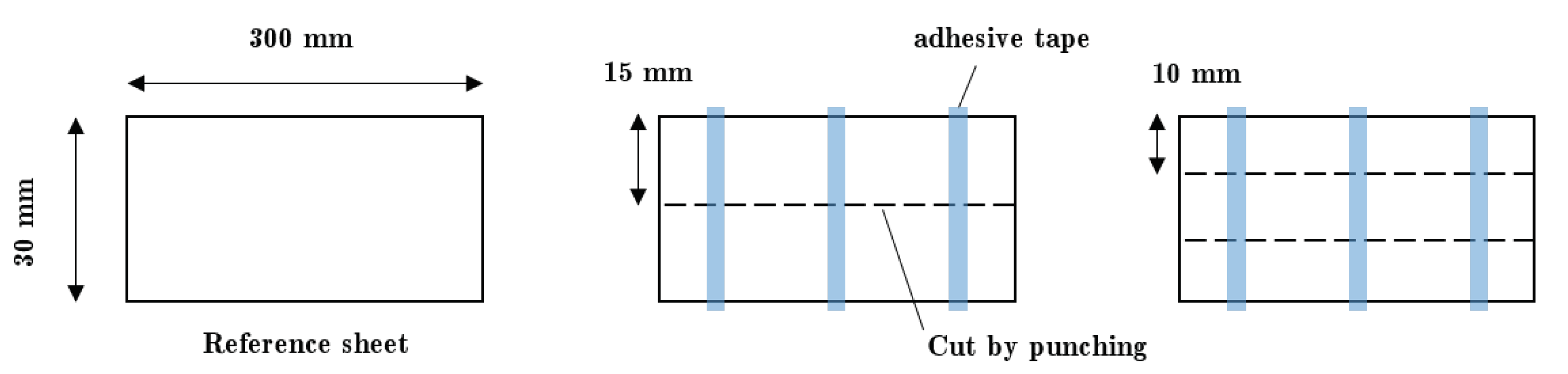
is a fitting function used to model the degradation at the cut edge. The effect of cutting is realized using electrical steel of different widths, as presented in the literature review. In line with these studies, a non-oriented electrical steel sheet of 50PN470 was investigated according to IEC 60404-3 with the test specimens of
mm. The cutting experiments of the test specimen of 30 mm × 300 mm were conducted on an industrial mechanical press. Consecutive cutting was performed as described in
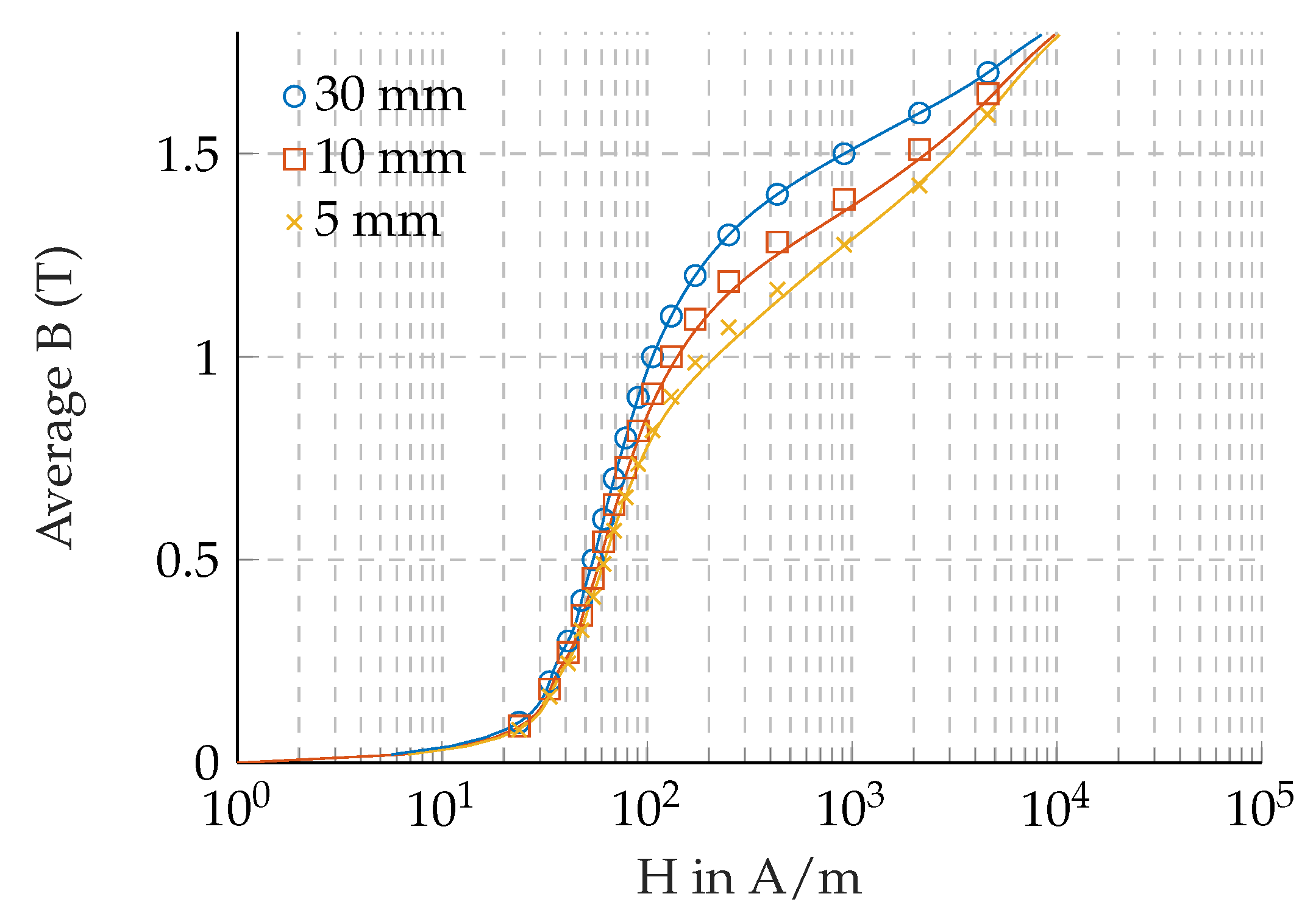
Figure 1 with cutting velocity corresponding to 60 strokes per minute, resulted in single samples of 15 mm, 10 mm, and 5 mm width. The samples were attached to each other with tape equalling total width of 30 mm. The relative cutting clearance was set to 10% of the sheet thickness which is 50 µm. This paper investigated with a new sharp cutting tool. It was not changed during the consecutive cutting. The fitting parameters were then estimated using the recorded average induction of the sample. The average induction of the fitting model is given by:
where
w is the width of the cut sample. The specimen 30 mm-wide was considered the non-degraded permeability. The single value BH curve fitted to the experimental results is shown in
Figure 2. From the parameter fitting that the effect of degradation disappeared exponentially, the local degradation is expected to be as much as 1.4 mm where the degradation is down to 5% of the maximum degradation at the cut edge. For a low-power motor of relatively small tooth width, the cutting effect may be more pronounced. The cutting effects on iron losses will be provided in the following iron loss subsection.
To include the local deterioration of the magnetic properties due to cutting in the FE simulation with MVP formulation, the deterioration had to be delivered as a function of the magnetic flux density, which is the unknown variable of the MVP formulation. The implementation used in the FE analysis to account for the nonlinear behavior will be introduced shortly.
2.1. FE Formulation
The behavior of magnetic materials is nonlinear, thus the FE equation itself is nonlinear. One of the approaches to solve a nonlinear vectorial equation is the Newton method, which uses Taylor series development to the 1st order [
21].
where
is a non-linear function defined in vector space. The matrix with a general term
is the Jacobian matrix of the system. In the FE formula with vector potential
A =
where
, respectively, is the function of nodal approximation and of the nodal variable. The solution of the FE problem in a current-free domain
is obtained by minimizing the following function [
21].
The Jacobian to solve the above function using the Newton method is written as follows:
For the isotropic material, the derivative in (6) for calculating the Jacobian in the
coordinate system can be expressed in terms of the reluctivity,
, as follows:
Thus, the physical data necessary to calculate the Jacobian is . In general, the reluctivity at the given flux density is interpolated to estimate the intermediate values of the given physical data. The derivative, , can be obtained from a regression model of the reluctivity.
The local cutting effect is incorporated in the FE simulation by assigning the cut-edge distance at each quadrature point of a mesh, such as
where
is the distance from the closest cutting edge. As given in [
17], use of a 2D reluctivity matrix as function of both flux density and cut-edge distance to evaluate the degraded reluctivity and the associated derivative at a particular quadrature point is an intuitive approach by which to account for the cutting effect in the FE simulation. However, the author finds that such a 2D reluctivity matrix must be built precisely to match the prescribed deterioration as described in (1), and that it occasionally fails to converge using the Newton method.
Because the MVP formula has flux density that is unknown, the permeability deterioration model given in (1) must be driven by the field flux density, not the flux intensity. This can be handled using the local Newton method to invert unknown field.
For a given flux density
, the field
H that minimizes the following residual needs to be identified.
By employing the Newton method, the iterations are generated from the initial guess obtained from the 2D reluctivity matrix
.
This is cheap to compute because a calculation of the time-consuming matrix inversion is not necessary for isotropic material. The Jacobian in (6) can be written by:
Once the local Newton method is terminated, each H component of an coordinate is obtained by , .
It is preferable to use the permeability rather than the reluctivity because the flux intensity, corresponding to the given flux density and the cut-edge distance, is a known value. The differential reluctivity given in (6) is the inverse of the differential permeability.
The inversion of a matrix is easy to do and (6) can be finally solved, starting from a solution of MVP at the current iteration and magnetic field state. The solution at the next iteration can be obtained by means of an iterative Newton scheme.
The lamination factor,
k, is accounted for in the actual implementation by the following simplified formula:
The flux density inside the iron should be re-evaluated assuming a constant H field in the stack of laminations to calculate the iron losses.
2.2. Cut Edge Distance
The cut-edge distance was assigned using the shortest distance between a quadrature point and a line segment connecting two nodal points of a triangular mesh in the punched area such as stator and rotor slots. The inner and outer radii of the stator were also considered to be cut edges. The rotor outer radius is formed by a grinding process, so the inner radius of the stator is accounted for to compute the cut-edge distance of a quadrature point. The calculation of the cut-edge distance is summarized as follows:
where
respectively is the quadrature point, the inner or outer radius of stator, and
d measure the closest distance to slots:
where
is the points of a mesh line segment at the slot edge. The parameter
is given by:
The distances, d, are computed for all line segments at the slot edge, and then the minimum among them is finally assigned for each quadrature point.
In this paper, a second-order shape function was used and six Gaussian quadrature points chosen, to evaluate (6) for each mesh area. To express accurately the deterioration, it is desirable to provide a fine mesh around the slots.
2.3. Iron Losses
The mechanical cutting causes increased iron losses such that the hysteresis component is mainly affected. The eddy-current losses are also affected due to the degradation of the insulation; however, this is insignificant [
7,
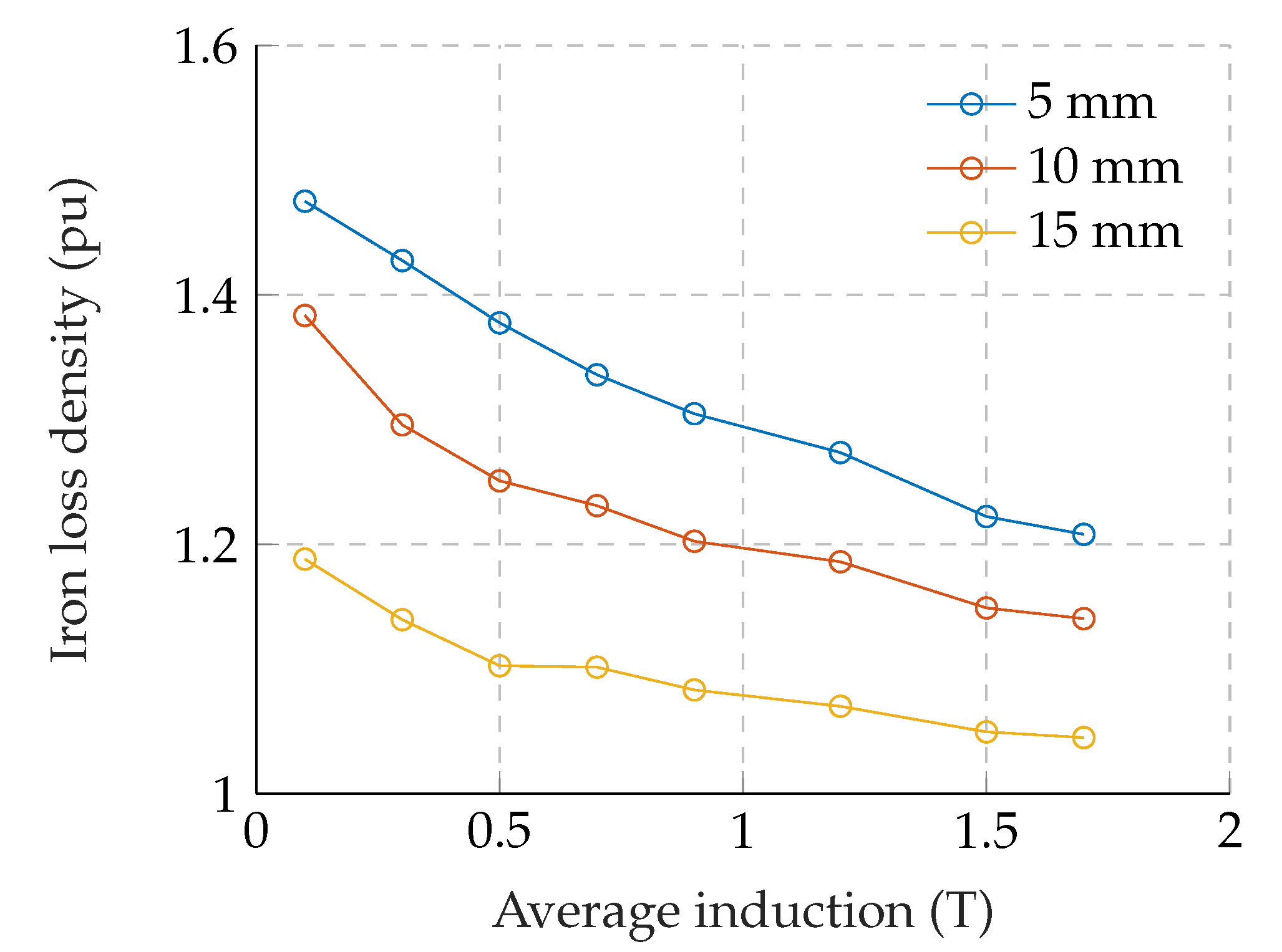
11]. This paper only considers the increased hysteresis losses with modified hysteresis loss coefficient for modeling the cutting effect. The coefficients of the eddy-current losses and excess losses are fixed at the annealed value. The hysteresis coefficient was modeled in a fashion similar to the locally degraded permeability. The local hysteresis loss was formulated as
where
are the hysteresis loss coefficients,
f is the frequency and the
are the fitting parameters. The average of (18) was fitted to the measured iron losses.
Figure 3 illustrates the iron losses that refer to the sample width of 30 mm. As can be seen, the increase in iron losses due to the cutting is lowered with increased induction. This justifies the employment of the logistic function in (18) as a function of the induction.
3. Results
The FE model described in
Section 2 was implemented on an open-source FE software, SMEKLIB, written in a Matlab environment [
22,
23]. The hysteresis loss parameters applied in this simulation are given in
Table 1.
The hysteresis loss parameters were chosen that best fit the experimental results for 60 Hz. The FE simulation was compared with two 2.2 kW prototype induction motors of which the iron lamination of one prototype was stacked with annealed iron lamination.
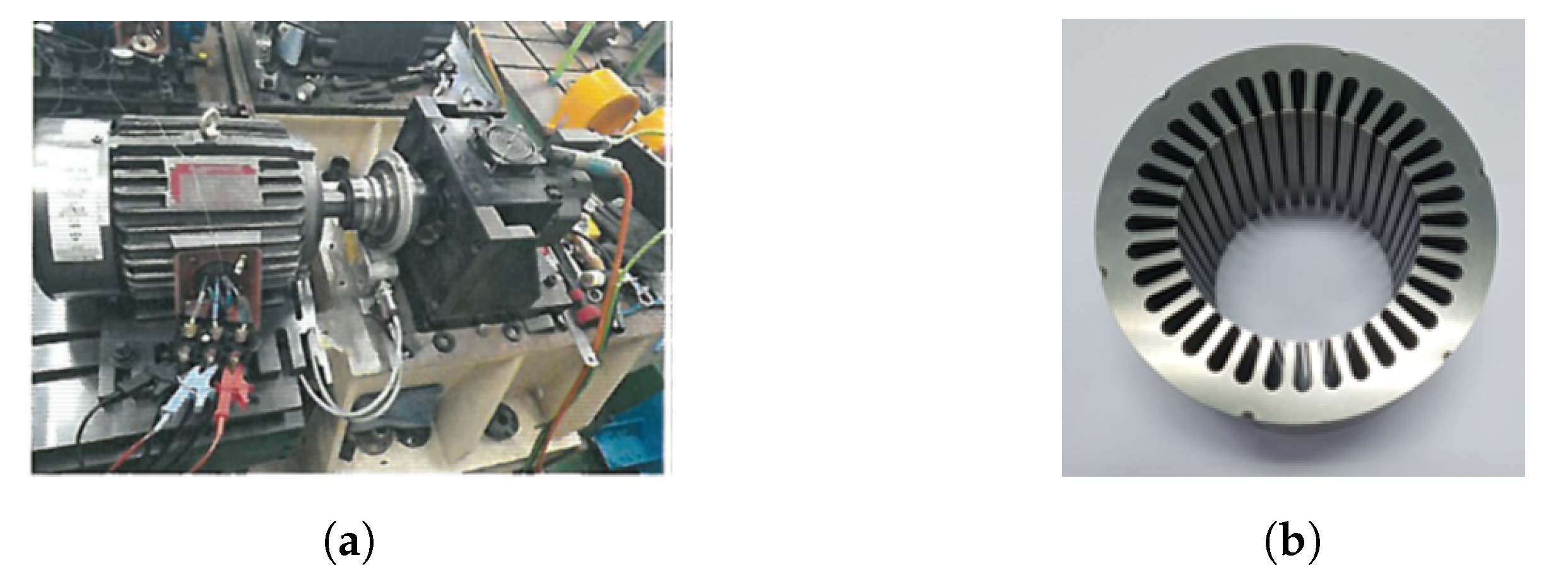
The induction motors rated at 2.2 kW were designed to achieve IE4 efficiency. The prototypes were manufactured and used in experiments according to the IEC-60034-2-1 standard. The experimental setups of the induction motor and the stator lamination are shown in
Figure 4 and the key data are given in
Table 2.
The iron lamination of one induction motor was annealed before the aluminum die-casting process was carried out to form the rotor cage. The maximum temperature of this process was 740 °C. Each lamination was stacked by interlocking, not by welding. The experimental results are given in
Table 3.
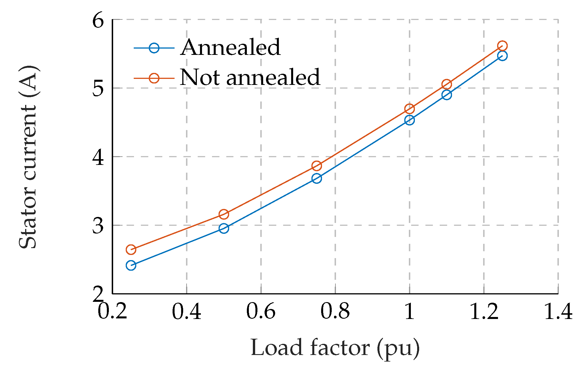
It should be noted that the segregated loss components in the table were calculated using the room temperature at the moment the experiments were conducted. The induction motor without the annealing process failed to achieve IE4 class efficiency (91.0%) when the loss components were rearranged to meet the ambient temperature of 25 °C. As it can be seen, the effect of cutting is visible in the stator current, hence the lower power factor of the motors. The measured stator currents with different load factors are compared in
Figure 5. The effect of cutting becomes more visible under the partial-load condition. The iron losses of the two motors were slightly different. It is worth noting that the iron losses calculated according to the test standard were convectional iron losses, not the actual iron losses [
24,
25]. Part of the additional losses would be iron losses; however, the experiments show almost identical additional losses of both motors, indicating that the increased iron losses due to the cutting process of these motors may be small. In summary of the experiments, the most notable effect of mechanical cutting is a change in the power factor that may be caused by degraded permeability.
Time stepping analysis with constant rotor speed obtained experimentally was carried out for the two 2.2 kW induction motors.
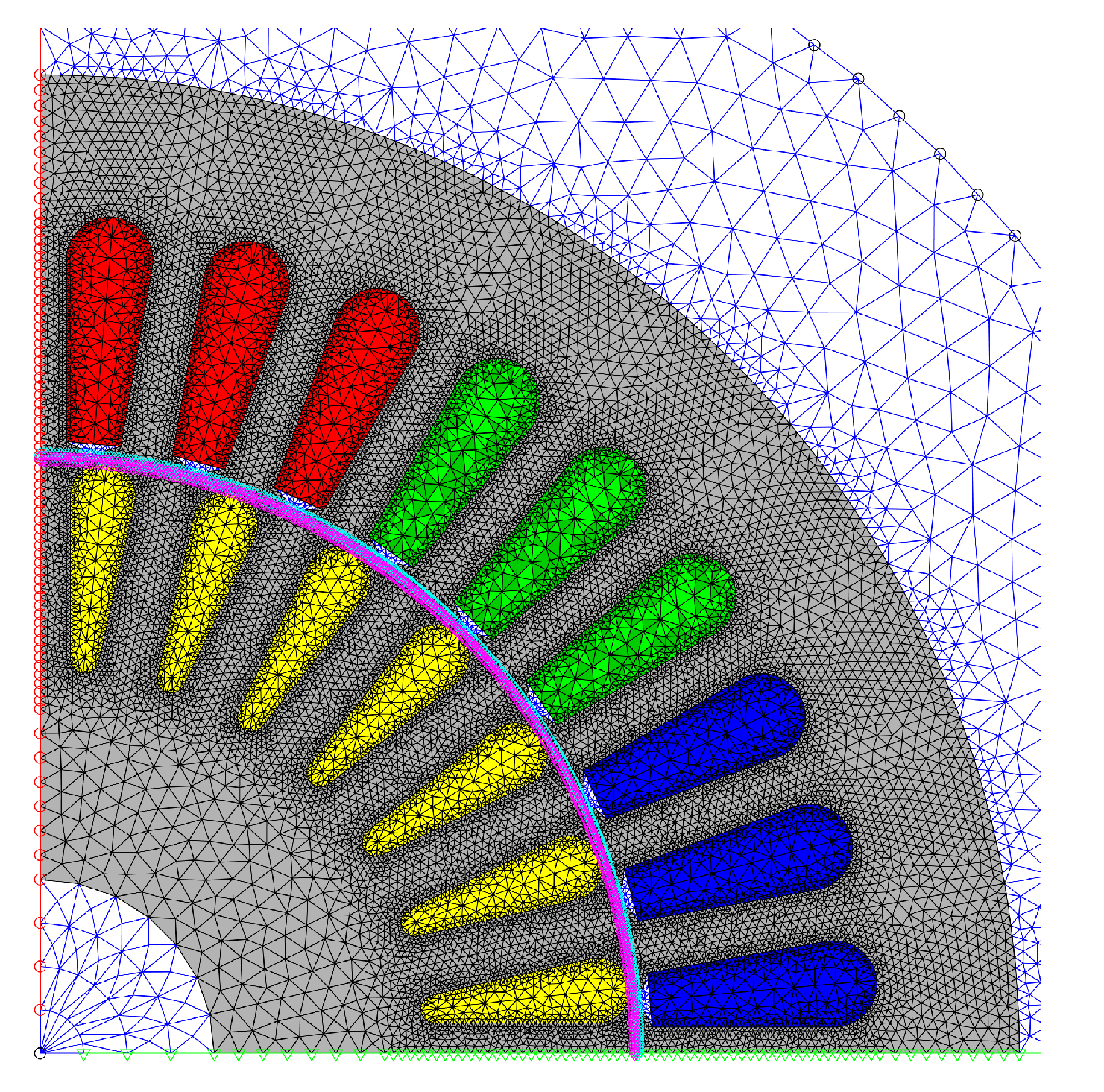
Figure 6 portrays the mesh of the FE simulation for the locally degraded permeability analysis. The slot-edge line was equally subdivided into segmented length of 0.3 mm to form a dense mesh around the slots. It results in a total number of mesh elements to 40436. Identical mesh was provided for the annealed case. The simulation has been performed with 8 times of a fundamental period resulted in total 960 time steps, starting from a time harmonic FEA for initializing rotor currents. In the time stepping FE simulation, the first-order Crank-Nicolson method was used to approximate time derivatives. The cutting effect on magnetic permeability was analyzed with the resulted fitting function as presented in
Figure 2.
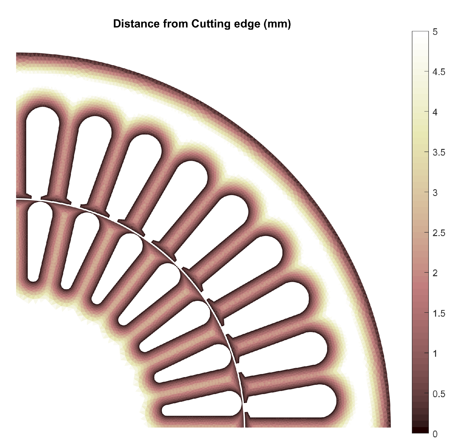
The cut-edge distance was assigned after the meshing process. The cut-edge distance assigned to each mesh is illustrated in
Figure 7. The distance was measured from the center of a mesh to the closest cut edge. In actual simulation, each of six Gaussian quadrature points of a mesh stored their own cut-edge distance. This was applied to calculate the functional calculus (6) and the Jacobian (12). The equivalent approach was used to calculate the iron losses. The effects of iron losses on the magnetic field were not included in this simulation, rather it was computed at a post process stage.
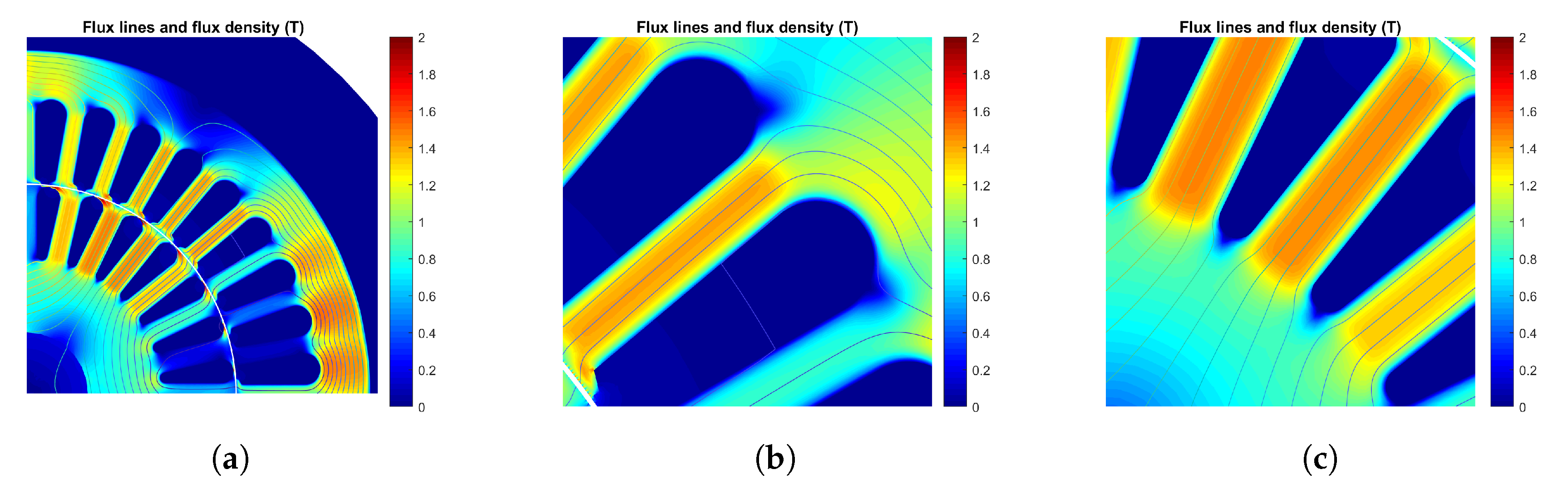
Figure 8 portrays the flux-density distribution with cutting effect at the rated rotor speed. It is clearly visible that the flux is concentrated in the middle of the stator and the rotor tooth. Moreover, the flux density distribution around the air gap is also weakened.
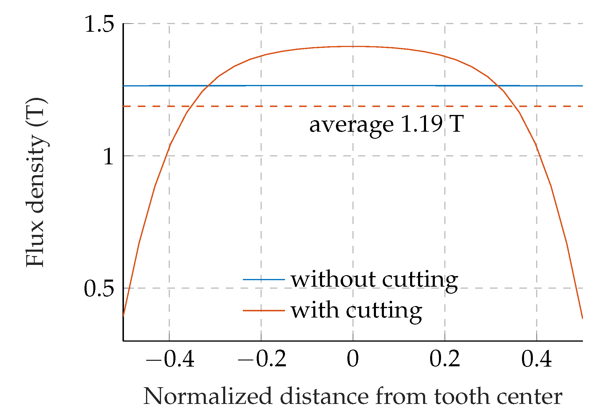
The radial flux density distribution of a stator tooth measured between two adjacent slots are compared in
Figure 9. As can be seen, the cutting effect forced the flux to concentrate in the middle, the peak of which is 1.41 T. The average radial flux density is 1.19 T for the simulation with cutting effect, which resulted in a decrease of 6.0% in the averaged value.
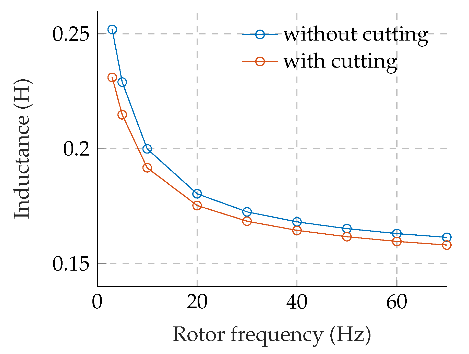
Figure 10 compares the magnetizing inductance of the induction motor extracted by time-harmonic simulation in a locked-rotor condition. At the rotor frequency of 3 Hz, the magnetizing inductance with cutting decreased to 91.7% of the inductance without cutting. As higher the rotor frequency, the discrepancy between their magnetizing inductances is lower. In the saturated condition, the permeability of the main flux path would be low enough that the degraded permeability near the cut edge might not cause significant effect when compare to the rated condition.
The overall simulation results are given in
Table 4. The hysteresis loss increased by 23.5%; however, the eddy current and the excess loss slightly decreased.
Apparently, the flux distribution close to the cut edge is weakened as shown in
Figure 9, which results in a decreased level of flux density in the tooth. This may explain the decreased eddy current and the excess losses. However, it should be noted that the eddy current and the excess loss were not included in the simulated magnetic field. It is unclear that the eddy current and the excess loss can actually be decreased due to cutting. The stator current increased by 0.18 A due to the cutting, while the other results such as torque and rotor-cage loss are almost identical in the two simulation results.
The properties obtained using the simulation are within an acceptable range of error when compared to those of the experimental results. In a low-power induction motor, the predominant effect from cutting is decreased magnetizing inductance, which yields higher stator currents. This would be more pronounced under the condition of partial load.
4. Conclusions
The 2D time-stepping magnetic field problem accounting for the locally degraded permeability due to cutting was implemented. The degraded permeability model intended to reveal the impact of cutting as a function of flux intensity was directly adopted by inverting the flux density, which is the unknown variable in the FE formula for MVP. The local Newton method was used to invert the flux density into the flux intensity. Then, the Newton method was applied again at the FE level.
As an example of cutting effects, the results of experiments on two 2.2 kW induction motors with IE4 efficiency were presented. The electrical steel lamination of one induction motor was accomplished by annealing before performing a die-casting process. The experimental results demonstrated that the major benefit of the annealing is decreased stator current. The magnetizing inductance with cutting effects, as calculated by time-harmonic FE analysis, dropped to 91.7% of the magnetizing inductance without cutting effects. The flux-density distribution of a stator tooth demonstrated the concentrated magnetic-flux phenomenon.
The FE simulations with cutting effects showed that the measured iron losses are almost identical regardless of the annealing. The hysteresis losses increased due to cutting; however, the overall iron losses remained almost same. The segregated iron losses from the FE simulation indicated decreased eddy currents and excess losses. These originated from a decrease in the induction level of the iron core.
The efficiency standard of electric motors is being tighten, the inclusion of cutting will be necessary in the motor-design stage. Not surprisingly, discrepancies between predictions and experimental results of electric motors are observed quite often. In future work, the local degraded model presented herein will be applied to predict performance of line-start synchronous reluctance motors. The author has discovered unacceptable disagreement between the predictions and experimental results regarding the power factor of those motors. The motor manufactured by laser cutting has recorded 6.8% decrement in the power factor compared to the prediction. It is expected that the cutting-effect model presented here, may allow correction of the discrepancy.


