Article

Research on the Starting Acceleration Characteristics of a New Mechanical–Electric–Hydraulic Power Coupling Electric Vehicle

1
College of Mechanical and Electrical Engineering, Qingdao University, Qingdao 260071, China
2
Power Integration and Energy Storage Systems Engineering Technology Center (Qingdao), Qingdao 260071, China
3
School of Mechanical Engineering, University of Science and Technology Beijing, Beijing 100083, China
*
Authors to whom correspondence should be addressed.
Energies 2020, 13(23), 6279; https://doi.org/10.3390/en13236279
Submission received: 30 October 2020 / Revised: 19 November 2020 / Accepted: 27 November 2020 / Published: 28 November 2020
(This article belongs to the Special Issue Advanced Electric Vehicle Techniques)

Abstract

:
To simplify the layout of a purely electric vehicle transmission system and improve the acceleration performance of the vehicle, this paper utilizes the characteristics of the large torque of a hydraulic transmission system and proposes a new mechanical–electric–hydraulic dynamic coupling drive system (MEH-DCDS). It integrates the traditional motor and the swashplate hydraulic pump/motor into one, which can realize the mutual conversion between the mechanical energy, electrical energy, and hydraulic energy. This article explains its working principle and structural characteristics. At the same time, the mathematical model for the key components is established and the operation mode is divided into various types. Based on AMESim software, the article studies the dynamic characteristics of the MEH-DCDS, and finally proposes a method that combines real-time feedback of the accumulator output torque with PID control to complete the system simulation. The results show that the MEH-DCDS vehicle has a starting time of 4.52 s at ignition, and the starting performance is improved by 40.37% compared to that of a pure motor drive system vehicle; after a PID adjustment, the MEH-DCDS vehicle’s starting time is shortened by 1.04 s, and the acceleration performance is improved by 23.01%. The results indicated the feasibility of the system and the power performance was substantially improved. Finally, the system is integrated into the vehicle and the dynamic performance of the MEH-DCDS under cycle conditions is verified by joint simulation. The results show that the vehicle is able to follow the control speed well when the MEH-DCDS is loaded on the vehicle. The state-of-charge (SOC) consumption rate is reduced by 20.33% compared to an electric vehicle, while the MEH-DCDS has an increased range of 45.7 m compared to the EV. This improves the energy efficiency and increases the driving range.

1. Introduction

With the development of electronic technology, especially the continuous improvement of power battery technology, storage batteries are widely used in the field of hybrid transportation. Energy storage batteries have a very high energy density and a very large storage capacity [1]. It also has good temperature performance and high rate discharge performance [2]. They also have a longer service life [3]. However, for purely electric vehicles, low-speed and heavy-duty vehicles, passenger cars, trucks, etc., the instantaneous high torque demand at ignition causes a large discharge current impact on the battery [4], which consumes much of the power and reduces the cycle life of the battery [5], decreasing the driving range of the vehicle [6]. Guo et al. [7] found that battery energy storage realizes energy recovery and reuse through the traditional power hybrid path. Wang et al. [8] developed a model that considers carbon emissions to simulate the recycling of electric vehicle batteries. A real-life case study of an electric vehicle manufacturer in China achieved a 5.7% reduction in total cost and a 21.8% reduction in CO2 emissions. At this stage, the technology is relatively mature and has been widely used in urban buses, but its shortcomings include charging and discharging, a low frequency, low power density, and high price.
Zhao et al. [9] presented a novel hydraulic/electric synergistic power system with multiple modes of operation. In this paper, the component sizes of a hybrid electric vehicle (HEV), hydraulic hybrid vehicle (HHV) and hydraulic/electric synergistic vehicle (HESV) are selected based on the dynamic performance of the target vehicle. Fiala et al. [10] introduced the principle of a hydraulic accumulator and applied the hydraulic accumulator in purely electric vehicles as a power source for auxiliary drive. Sun et al. [11] proposed an energy-saving solution for a parallel hydraulic hybrid power system. This gives full play to the advantages of the hydraulic accumulator’s high power density and its ability to efficiently store and release large amounts of energy, which can effectively overcome the disadvantages of battery energy storage. At the same time, it is relatively inexpensive and has a broader application prospect. Pugi et al. [12] presented an on-board hydraulic drive system capable of efficient recovery of braking energy. The system was subsequently applied in practice with a truck equipped with a hydraulic tool for waste collection. The design, assembly and testing of the system prototype showed that the efficiency of the system was improved accordingly and that the proposed method was feasible. Wang et al. [13] combined the high energy density of hydraulic accumulators and designed a strategy to improve fuel economy. The results show that the average fuel consumption per gallon of the proposed strategy, compared with the rule-based control strategy and the proportional integral derivative controller-based control strategy, increased by 7.3% and 5.9%, respectively.
Pretto et al. [14] presented a simple and inexpensive electrification device for the problem of low profitability of light duty tricycles. The solution discusses the profitability of light truck electrification in terms of energy prices in different countries, which allows to upgrade existing vehicles with limited investment. Special attention is paid to the optimization of regenerative braking and its blending with mechanical braking to maximize autonomy and maintain vehicle stability. Very little research has been done on this new electro-hydraulic hybrid powertrain. The economics of the vehicle are one of the most pressing issues to be addressed before it can be truly marketed and industrialized.
Zhou et al. [15] proposed a set of parallel hydraulic hybrid vehicles that integrate conventional engines and hydraulic pump/motors to independently or jointly drive vehicles. The results show that the comfort and driving performance of the transition from the hydraulic mode to engine mode are improved. Niu et al. [16] proposed and designed a parallel electro-hydraulic hybrid power system and applied it to urban vehicles. The experimental results show that the system can reduce the discharge intensity of urban trucks by 30% and extend the mileage of urban buses by 50% under frequent urban operating conditions. Hwang et al. [17] designed a hydraulic hybrid vehicle and used reverse simulation to simulate the changes in torque and battery state-of-charge (SOC) during the cycle of the United States Environmental Protection Agency (EPA NYCC) in New York City. The simulation results show that the electric economy of the designed hydraulic hybrid vehicle is 36.51% higher than that of a purely electric vehicle. Sprengel et al. [18] proposed a new type of hybrid hydraulic structure and performed six operating modes on the test bench under urban cycle conditions, and the results showed that the fuel economy of the system is improved by 17.35%, while the energy consumption is reduced by 12.04% for this hybrid hydraulic hybrid compared with the series hydraulic hybrid power system. In 2017, Geng et al. [19] developed an electro-hydraulic hybrid power transmission system for urban vehicles. The simulation results showed that the battery discharge pressure of urban delivery trucks can be reduced by an average of 30%. In the best case, the mileage of urban buses can be extended by 50%. Midgley et al. [20] designed a hydraulic regenerative braking system composed of high- and low-pressure accumulators. The potential of the system for crossing a hilly terrain has been studied, and it was found that the system can reduce fuel consumption by 12.6% on V-shaped valley, and by 5.3% on real elevation profiles. Wang et al. [21] comprehensively used the advantages of the high energy density of the battery and hydraulic accumulator and established the AMESim and Simulink co-simulation model of the power transmission system, which verified the feasibility of the system. Finally, an experimental platform was built, and the effectiveness of the transmission system was verified through experiments.
In this paper, a hydraulic-assisted, mechanical–electric–hydraulic dynamic coupling drive system (MEH-DCDS) is designed that makes full use of the high power density of hydraulic power. It can integrate the traditional permanent magnet rotating motor with the swashplate axial plunger pump/motor, and it can mutually convert electrical energy, mechanical energy, and hydraulic energy. It can be widely used in automobiles, construction machinery, agricultural machinery, and machine tools. It is especially suitable as a power transmission device for electric commercial vehicles. The MEH-DCDS for the power system and the hydraulic system of the dynamic coupling was designed and integrated into an organic whole. It fully combines the advantages of the two, changes the driving method, and optimizes the structure of the transmission system. It greatly prolongs the service life of the battery and increases the mileage of the vehicle. At the same time, it significantly improves the power performance and fuel economy of vehicles.

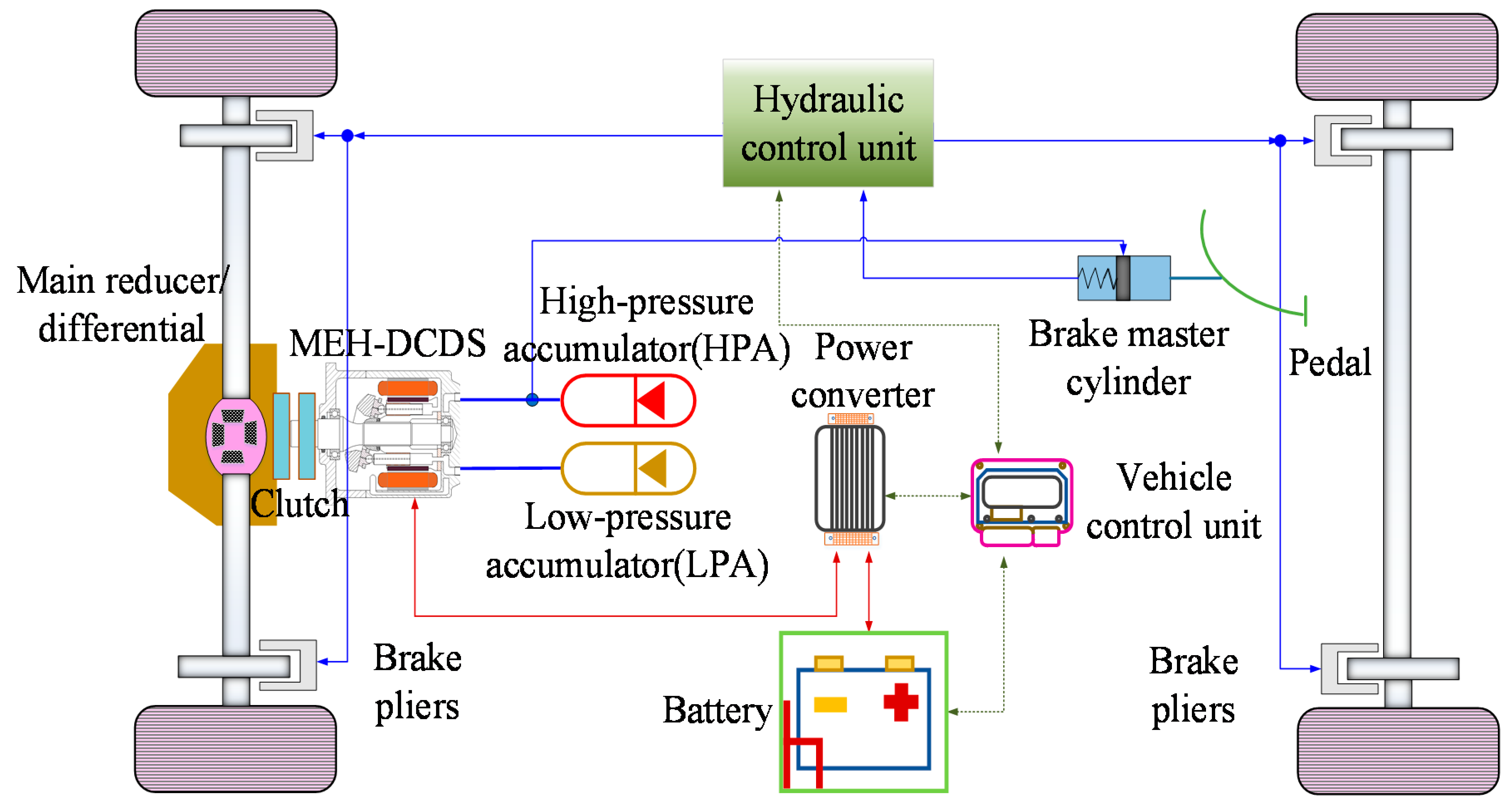
2. The Working Principle of the MEH-DCDS

The MEH-DCDS is designed in combination with the working principle and characteristics of electro-hydraulic transmission [22,23,24]. Based on purely electric vehicles, high and low hydraulic accumulators are added. The electro-hydraulic coupler replaces the electric motor and the hydraulic pump/motor and can be torque-coupled to the output driving force, integrating mechanical energy, electrical energy, and hydraulic energy. It satisfies the application needs of many occasions and achieves better energy-saving effects through complementary advantages. During braking, part of the braking energy is recovered and stored in the hydraulic accumulator and battery for use in high-power demand conditions, such as starting and acceleration, which improves the starting characteristics of the vehicle, reduces the effect of high torque demand on the battery SOC and achieves the purpose of extending the service life of the battery and increases the driving range of the vehicle.
As shown in Figure 1, the MEH-DCDS vehicle includes an electro-hydraulic coupler, high-pressure accumulator (HPA), low-pressure accumulator (LPA), final drive/differential, clutch, secondary components, a power converter, vehicle controller, power battery pack, etc. The battery is the power source of the power system, and the electric power is the main power form of the power system. The hydraulic power is converted from electric power and plays an auxiliary driving role. When the system is working, the controller receives the acceleration signal, the brake signal, and the signal from the pressure sensor, and transmits it to the hydraulic control unit after the vehicle controller to adjust the displacement of the hydraulic pump/motor. When the vehicle starts, the electric power does not output power, the hydraulic pump/motor is used as the motor, and the hydraulic oil flows from the HPA to the LPA. After the hydraulic power drives the vehicle to accelerate to a certain lower speed, the motor traction system is involved in work to reduce the effect of a high current and high torque when the vehicle starts. If the pressure in the hydraulic accumulator reaches the minimum working pressure of the accumulator, the hydraulic power stops working, the motor selects the opportunity to drive the hydraulic pump/motor to charge the hydraulic accumulator in the blank working condition, and the hydraulic pump/motor is used as a pump. The oil flows from the LPA to the HPA. During the acceleration and climbing stage, electric power intervenes to work together with the hydraulic pump/motor to perform torque coupling and output power to drive the vehicle to accelerate and climb. During the constant-speed driving phase of the vehicle, because of the stable speed and small external load, the hydraulic system does not intervene in the work and only the electric power drives the vehicle to cruise. In idling conditions, electric power is used as a power source to drive the secondary components to work in the state of a hydraulic pump, pumping the oil of the LPA into the HPA, and at this time, the electrical energy is converted into hydraulic energy to store energy in the accumulator over time. When the vehicle is operating at a low speed, the hydraulic system recovers braking energy, and ABS braking is used for emergency braking without braking energy recovery. In other braking conditions, the braking energy is primarily recovered in the form of electrical energy at high speeds. At a medium speed, the braking energy is primarily recovered by electric and hydraulic energy at the same time.
Compared with traditional fuel vehicles and purely electric vehicles, the main advantages of the new MEH-DCDS are as follows:
(1)
The MEH-DCDS replaces the drive motor, transmission, and auxiliary drive system of traditional electric commercial vehicles. It optimizes the structure of the transmission system. Various power conversions are optimally matched through structural parameters within the system, which improves the transmission efficiency and makes the entire power transmission system more efficient. It also has a self-cooling function and compact structure.
(2)
Because of the high power density, hydraulic power can quickly start the car and double the car’s grade ability. It substantially improves the dynamics of the vehicle and greatly reduces the peak power of the electric power; when the MEH-DCDS brakes, hydraulic regenerative braking, electric regenerative braking, and friction braking (ABS braking) work together. This design decreases the braking distance and results in a more stable recovery of hydraulic power (over 70%).
(3)
The MEH-DCDS reduces the current impact caused by changes in vehicle load and the damage to the battery and electronic control system caused by the current impact. It reduces the utilization rate of the friction brake system, greatly improves the service life and reliability, and substantially increases the driving range.

3. Mathematical Modeling of the MEH-DCDS

The MEH-DCDS integrates electric power and hydraulic power [25], combining the traditional permanent magnet synchronous motor and hydraulic pump/motor into a whole, so the analysis of electric power includes battery and motor modules, and the analysis of hydraulic power is performed on the hydraulic pump/motor [26]. This part of the paper mainly establishes the mathematical models of hydraulic power, hydraulic accumulators, and electric power modules [27].

3.1. Hydraulic Power

When the vehicle starts, the secondary element is used as a hydraulic motor to drive the vehicle alone; when the vehicle is accelerating, the secondary element is used as a hydraulic motor, and the electric power is torque-coupled to output power; during braking, the secondary element is used as a hydraulic pump to store the excess braking energy in the hydraulic accumulator in the form of hydraulic energy [28,29].
The swashplate opening β and output torque Tp of the hydraulic pump/motor can be described as
{ 1 β 1 T p = Δ p V p β 2 π η p
where β is the opening of the swashplate, (−1, 1); ∆p is the inlet and outlet pressure difference; Vp is the displacement; and ηp is the mechanical efficiency of the hydraulic pump/motor.

3.2. Electric Power

The battery is a very important power source in the MEH-DCDS. When the power is insufficient, the battery is used to provide part of the power, and at the same time, it can convert part of the braking energy into electrical energy for storage [30]. Therefore, the battery is the core of the hybrid drive system, and its dynamic characteristics analysis is very important. The total efficiency of the motor is 0.855, and the peak power of the battery pack should be greater than the maximum power of the motor; then, the formula for calculating the maximum power of the battery pack is as follows:
P b = P max η b
where Pmax is the maximum power of the motor/generator design; Pb is the maximum power of the battery pack; and ηb is the total efficiency of the battery bank. Therefore, Pmax = 30 kW is selected, and the maximum power of the battery pack Pb = 35 kW is calculated by substituting the parameters.
Choose a battery pack with a rated capacity of 65 Ah. The battery pack consists of a number of cells. The monoblocks are arranged in series. Initially, the rated voltage Ubc of the NiMH cell is 1.29 V. According to the maximum power of the battery pack design, the total number of cells nbc of the battery pack is calculated as follows:
P bc = U bc 2 4 R bc
n bc = 1000 P max P maxc
where Ubc is the rated voltage of the single cell and Rbc is the internal resistance of the single cell. The mean value of 0.0026 Ω is taken here.
According to the calculated total number of cells, nbc = 219, and every 40 cells are connected in series according to the actual situation and the arrangement of the cells. Here it is rounded to 6 groups, so nbc = 240 is selected. The formula for calculating the rated voltage of the battery pack is:
U b = n bc U bc
The nominal voltage of the battery pack is calculated to be Ub = 310 V. Figure 2 shows the schematic diagram of the battery pack. The specific parameters of the battery pack are shown in the Table 1 below.
In the MEH-DCDS, the motor is used to drive the vehicle to accelerate, charge when the energy of the accumulator is insufficient, and recover the braking energy during braking. The input torque of the motor Treq is subject to a limited torque limit of Tlim:
T min T lim T max
where Tmin is the minimum torque of the motor, and Tmax is the maximum torque of the motor.
The output torque Tm of the motor is determined from the limit torque Tlim using a first-order lag:
T m = 1 1 + t r s T lim
where tr is a user-defined time constant.
The mechanical power Pmec and power loss Plost of the motor are calculated as follows:
{ P mec = T m n e 9549 P lost = ( 1 η e ) | P mec |
where ne is the rotary velocity of the motor shaft.
The different operating modes of the electric motor/generator can be illustrated in Figure 3.
So, the relation between the mechanical and the electric power is the following:
P elec = P mec P lost
The motor/generator efficiency corresponds to:
{ η m = 2 P elec P mec η g = P elec P mec
where Pelec is the electric power; ηm is the motor efficiency; and ηg is the generator efficiency.

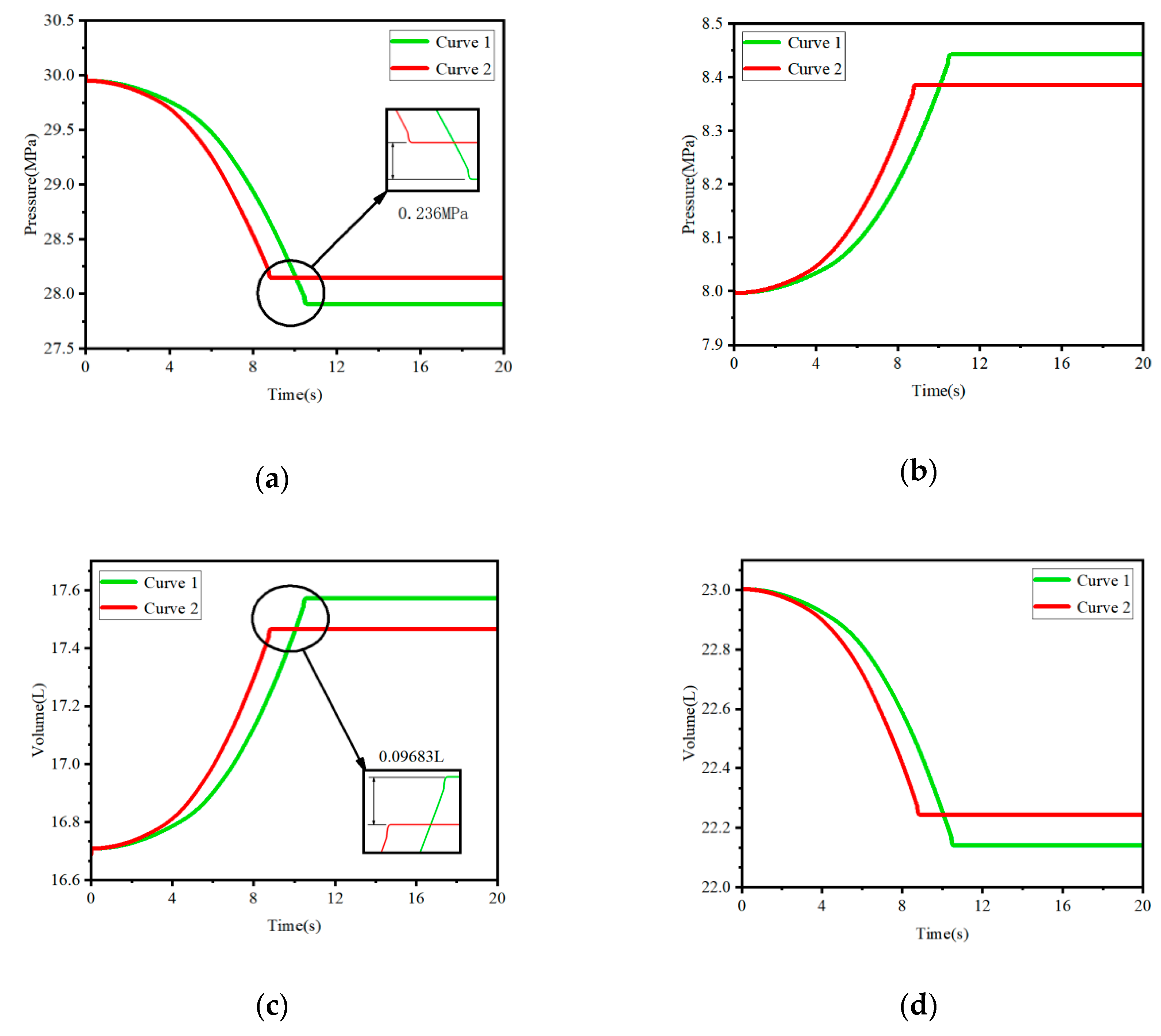
3.3. Hydraulic Accumulator

As the starting power source of the MEH-DCDS, the hydraulic accumulator is also the storage unit of braking energy recovery. Compared with batteries, it has the characteristics of fast starting and a large instantaneous torque. According to Boyle’s law, the relationship between pressure and volume is
P 0 v 0 n = P 1 v 1 n = P 2 v 2 n
where P0 is the pre-charging pressure of the gas; v0 is the accumulator charging volume; P1 is the lowest working pressure of the accumulator; v1 is the gas volume before the accumulator works; P2 is the accumulator maximum working pressure; and v2 is the gas volume after the accumulator works.
When the accumulator is working, there can be three modes, and its dynamic calculation depends on the accumulator mode:
(1)
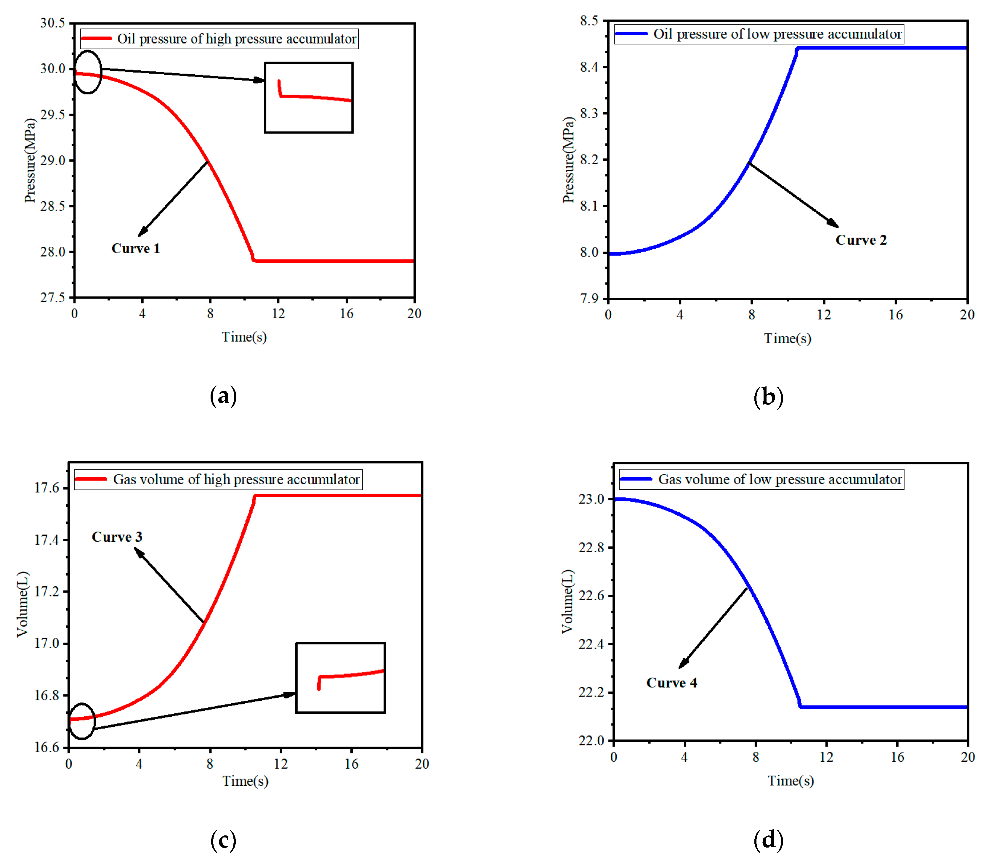
If the energy of the accumulator is sufficient, the gas pressure of the accumulator is at the maximum, and the volume is at the minimum, hence:
{ P gas = P max V gas = V 0 1000
where Pgas is the gas pressure; Pmax is the maximum pressure; Vgas is the gas volume; and V0 is the accumulator volume.
(2)
If the accumulator has been completely discharged, the gas pressure of the accumulator is at the pre-charge value, and the volume is at the maximum, hence:
{ P gas = P 0 V gas = V 0
(3)
If the accumulator is neither fully discharged nor fully charged, the air pressure is identical to the hydraulic pressure:
P gas = P out
where Pout is the output pressure of the accumulator.
The volume of gas is calculated using the law of many parties:
V gas = V 0 ( P 0 P gas ) 1 γ

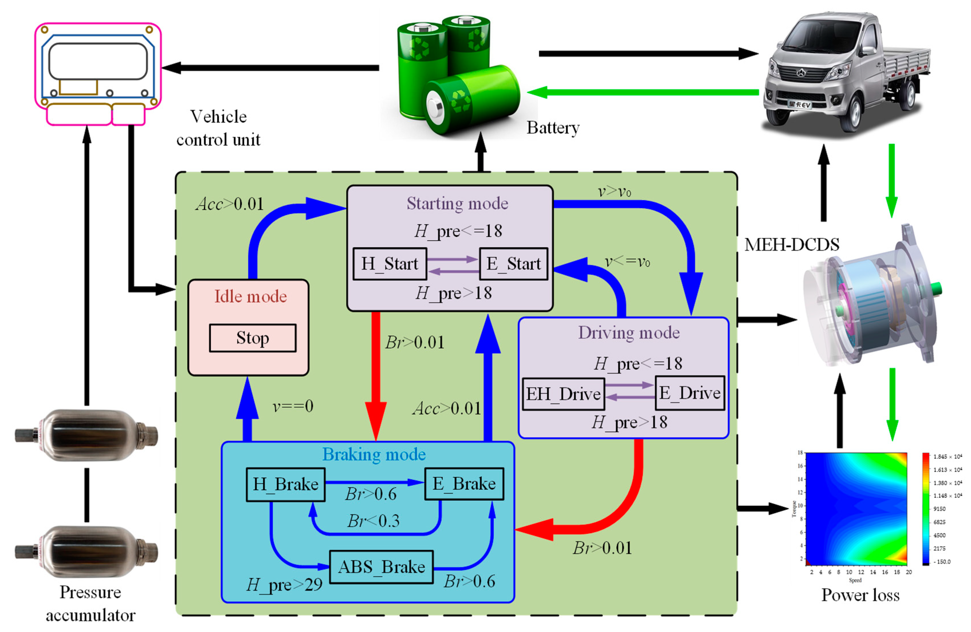
4. Analysis of the Working Mode and Energy Management Strategies

The MEH-DCDS has multiple working modes. As shown in Figure 4, the working modes of the MEH-DCDS are roughly divided into five types [31,32]. Each working mode is independent of the other working modes. When formulating the control strategy according to different working conditions, this paper formulates the ruled control strategy of the MEH-DCDS. In the AMESim software, the formulation of the control strategy is realized through the construction of formulas. The vehicle speed threshold and the pressure of the high-pressure accumulator are used as the basis for mode switching to complete the simulation of the system. Figure 5 shows the control strategy of the MEH-DCDS.
(1)
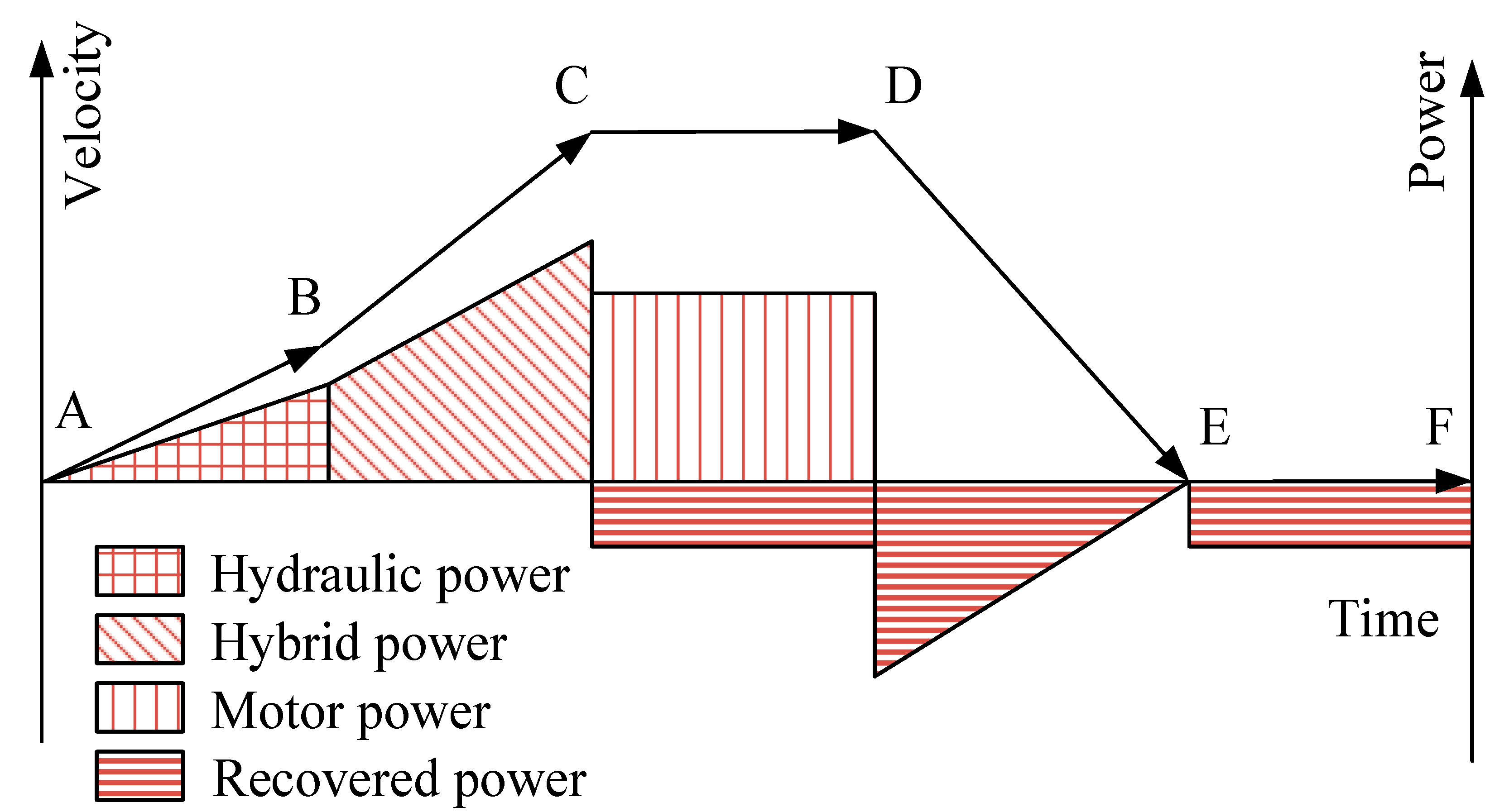
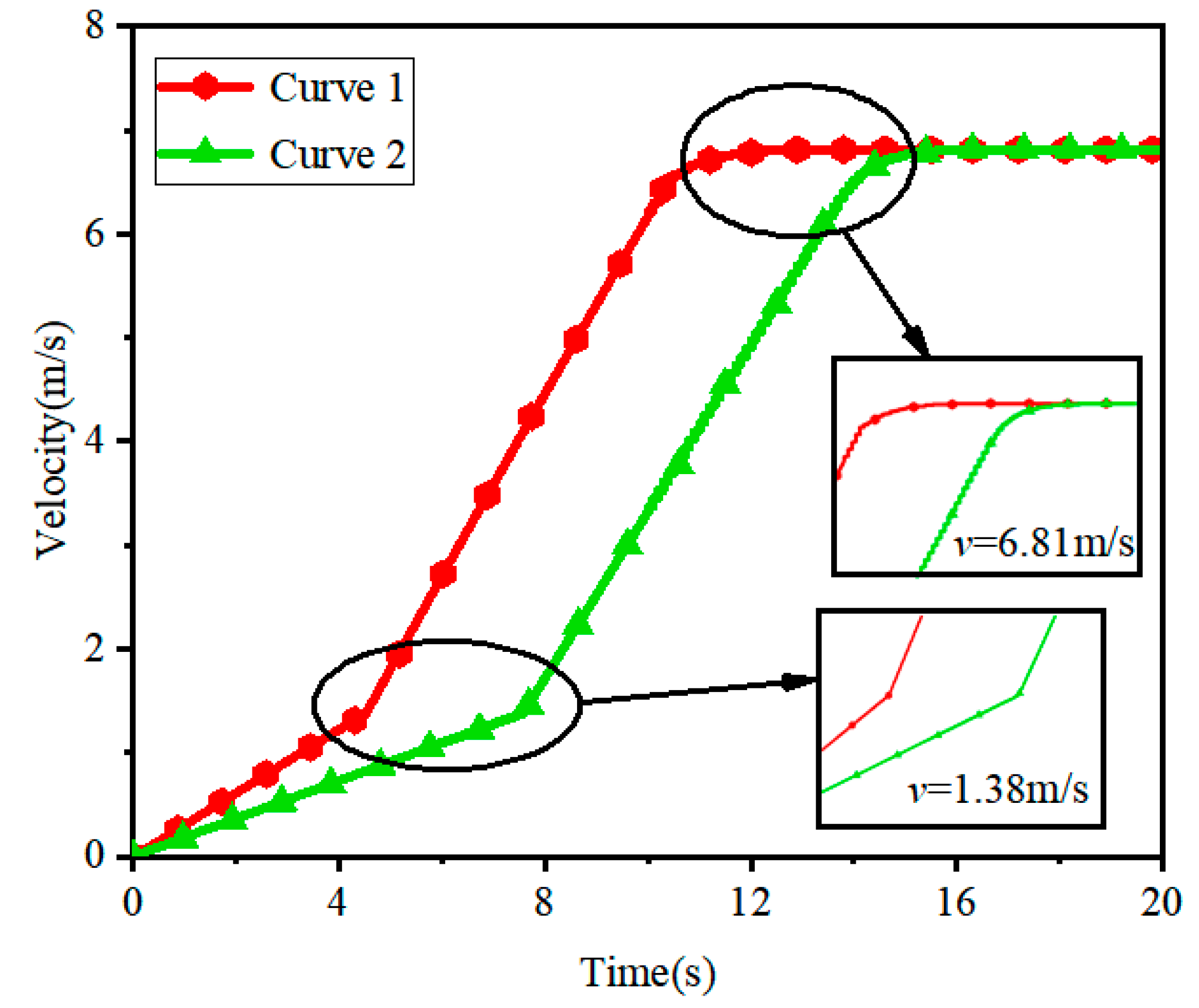
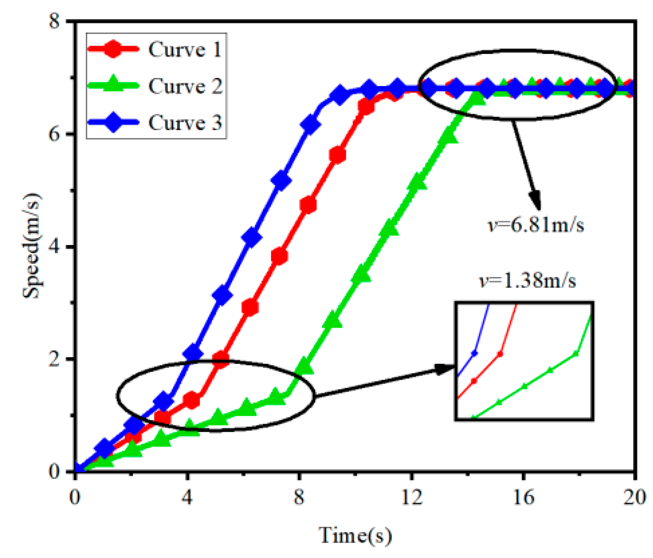
Starting mode: As shown in section AB, the starting torque of the vehicle is greater during starting. The required peak torque makes the battery pack in a high current discharge state, which has a greater effect on the battery SOC. Therefore, when the vehicle begins to accelerate, only the hydraulic system drives the vehicle. When the pressure of the high-pressure accumulator in the hydraulic system is greater than the pressure of the low-pressure accumulator, the secondary element works in the motor state. All the solenoid valve switches are turned on. At this time, the hydraulic oil in the high-pressure accumulator flows to the low-pressure accumulator. The oil drives the hydraulic motor to rotate and converts the hydraulic energy stored in the hydraulic accumulator into mechanical energy. When the pressure is lower than the minimum working pressure of the accumulator, the hydraulic accumulator cannot release the hydraulic oil. At this time, the battery pack drives the electric motor/generator to charge the hydraulic accumulator.
(2)
Acceleration/climbing mode: As shown in section BC, the torque required for the vehicle to climb or accelerate must be sufficiently large to meet the driving requirements. After the vehicle is started, it accelerates to the vehicle speed threshold, and the battery pack begins to provide electrical energy. The electrical energy is converted into mechanical energy through the motor and coupled with hydraulic energy torque to achieve power mixing. It outputs electrical energy and hydraulic energy together as mechanical energy, which is converted into kinetic energy by the wheels to drive the vehicle to reduce the electrical power and current impact and increase the driving range.
(3)
Constant speed mode: As shown in the CD section, under uniform speed conditions, the traction of the vehicle needs only to overcome frictional resistance and slope resistance. The external load of the vehicle is relatively small during the start and acceleration conditions. At this time, the solenoid valve switch is closed, the hydraulic system does not operate, and the electric power alone outputs torque to drive the vehicle at a constant speed. Under this working condition, the motor can work in a high-efficiency region to a large extent. In addition, when the output power of the motor is large, the abundant power of the motor can also charge the hydraulic accumulator to further improve its operating point, not only to make the motor work stably in the high-efficiency region but also to reserve for operating conditions that require instantaneous high-power energy.
(4)
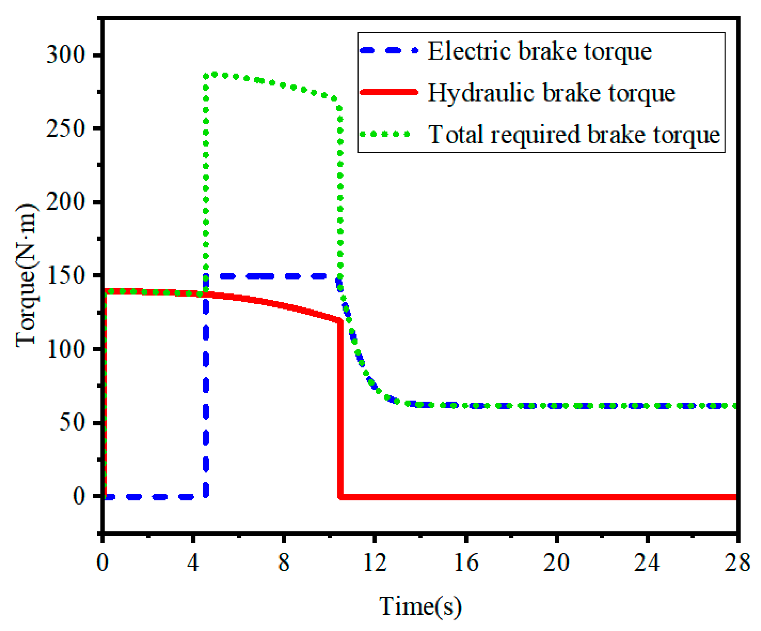
Braking mode: As shown in section DE, when the vehicle is decelerating and braking, the regenerative braking energy is converted into hydraulic energy and recycled into the high-pressure accumulator. The remaining energy is converted into electrical energy by the generator and stored in the battery, which reserves a certain amount of hydraulic energy for the vehicle’s starting and acceleration conditions.
(5)
Idle mode: As shown in section EF, when the vehicle is idling, the electric power does not output mechanical energy to the outside. Instead, it converts electrical energy into hydraulic energy to charge hydraulic accumulators, which store energy for vehicle starting and working conditions that require instantaneous high power.
In summary, the MEH-DCDS control strategy is primarily designed for how to select the power source under different operating conditions of the vehicle. For the study of the MEH-DCDS, the expected vehicle speed is used as the control input signal, and the battery SOC and the pressure and energy storage conditions of the high- and low-pressure accumulators are monitored in real-time to achieve the desired effect of the actual vehicle speed. Table 2 shows the energy flow direction of different working modes.

5. Simulation and Analysis

5.1. Basic Parameters

The parameters of the MEH-DCDS are based on the dynamic requirements of the vehicle. The fundamental parameters are shown in Table 3.

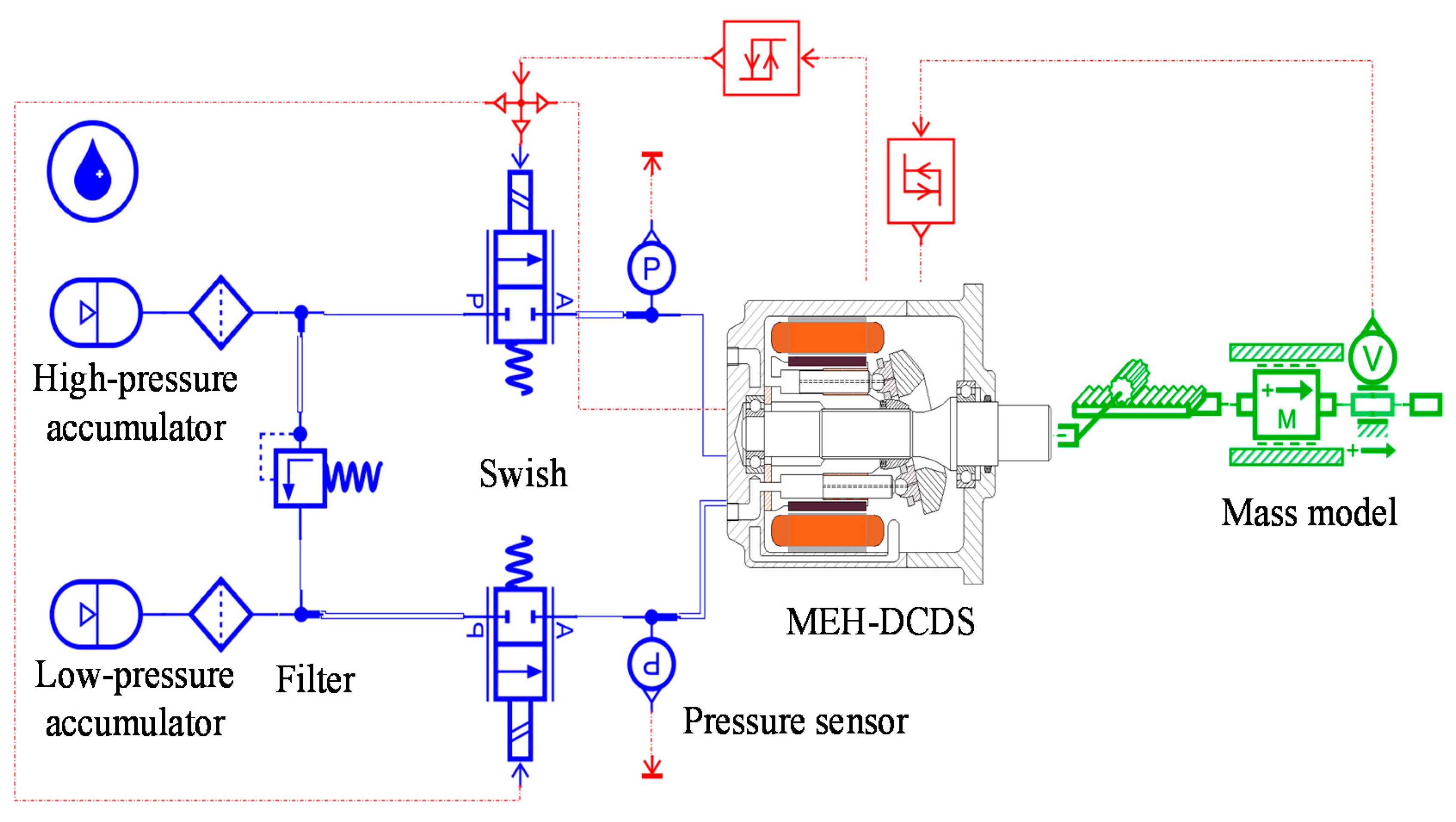
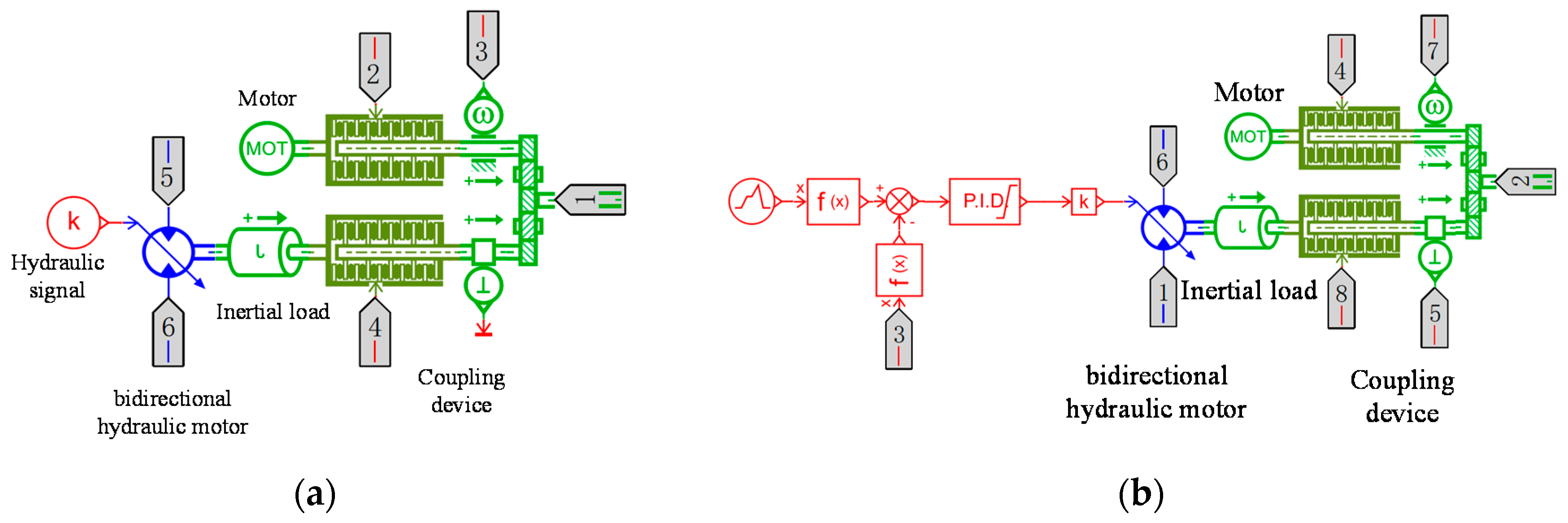
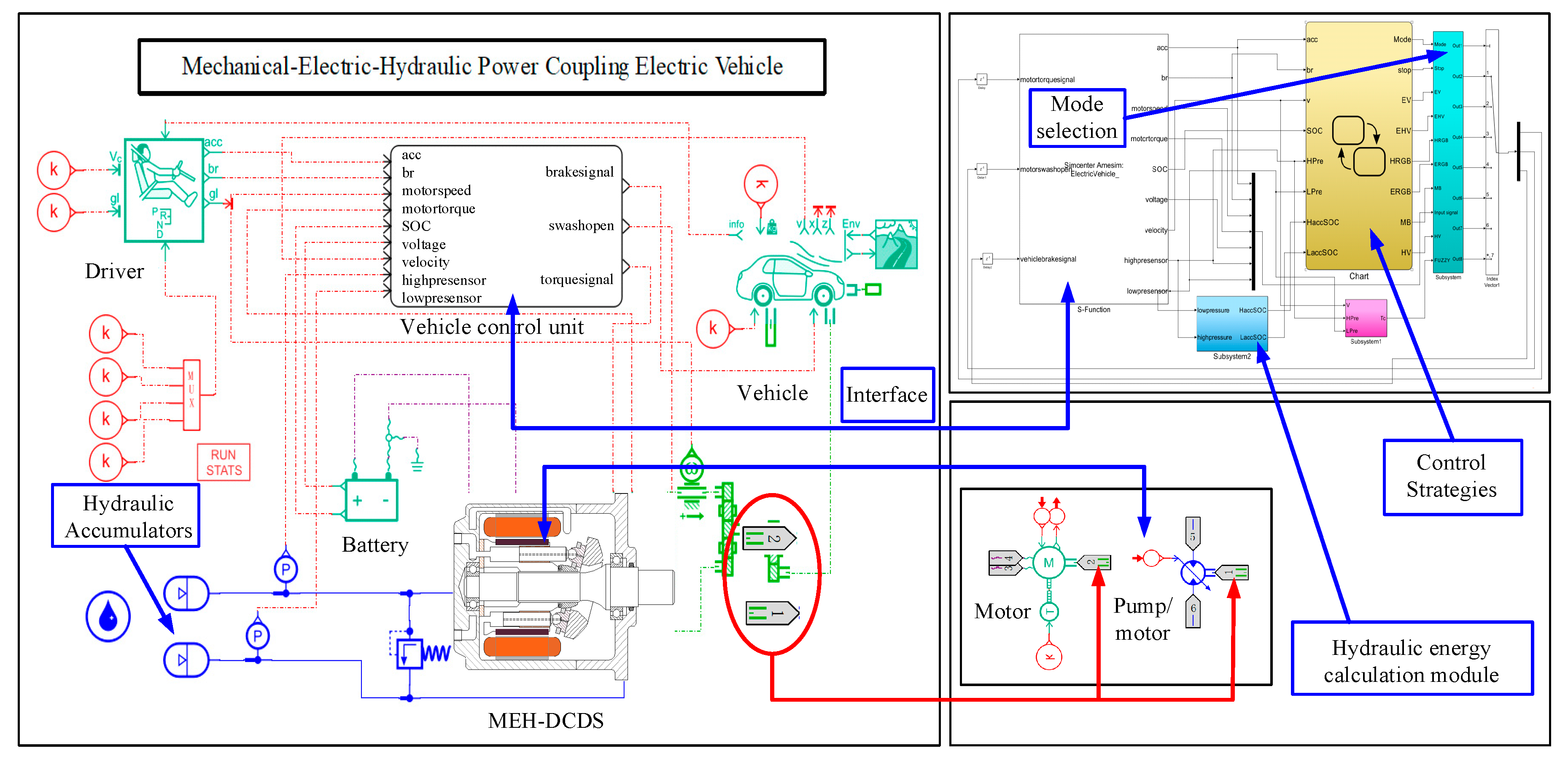
5.2. Simulation Model

The MEH-DCDS simulation model established in the AMESim software is shown in Figure 6. The vehicle powertrain model consists of a motor model, a battery model, a wheel model, and a road model. The mass block is used to simulate the mass of the entire vehicle and the load resistance. The torque after the electric motor and the hydraulic motor are coupled is transformed into the driving force input of the mass block.
The MEH-DCDS integrates the secondary component and the motor. It is represented as a whole in Figure 6, and in AMESim it is composed of a motor model, hydraulic pump/motor model, hydraulic signal, switch, coupling mechanism, etc., as shown in Figure 7.

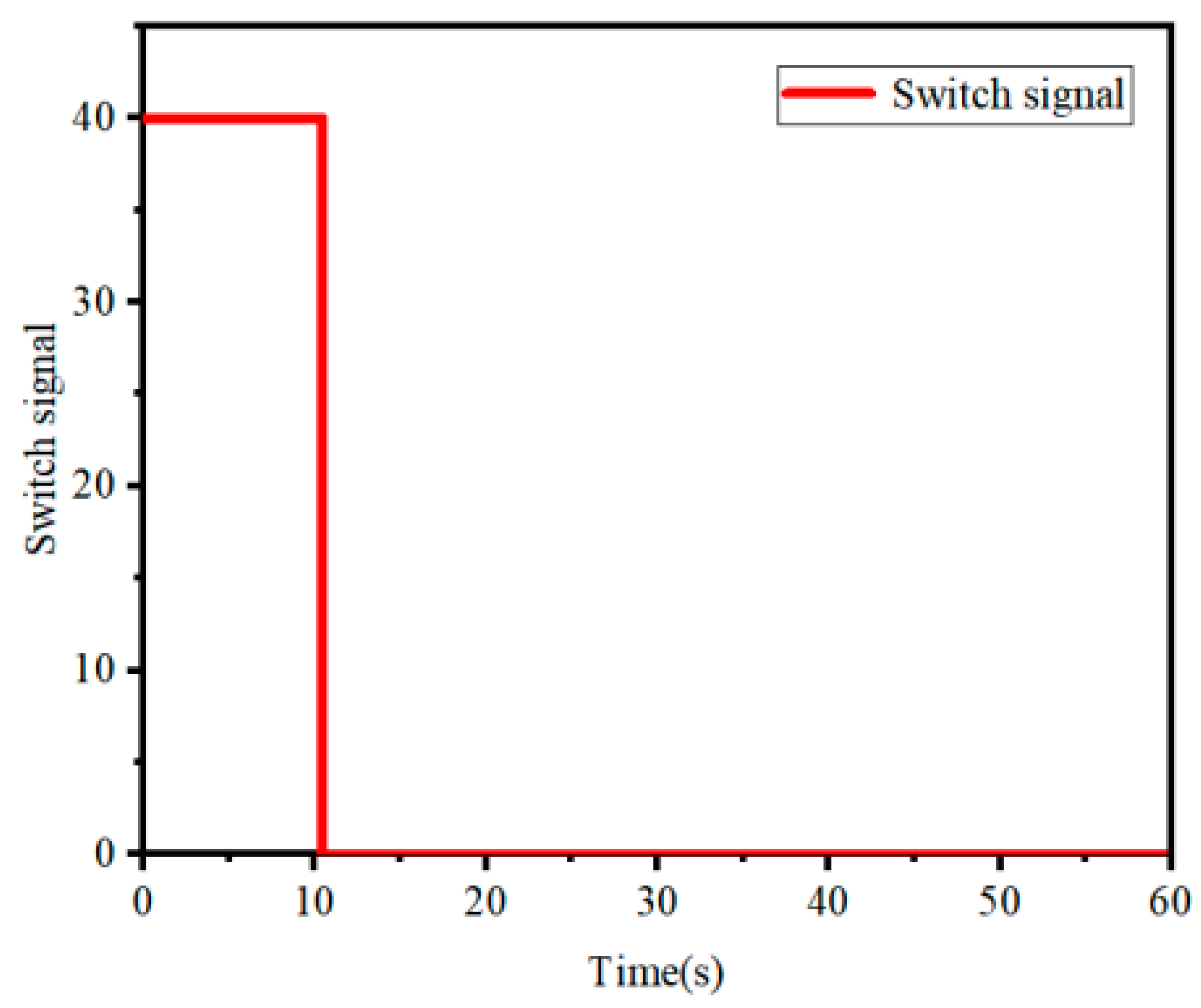
5.3. Analysis of the Simulation Results

(1) Analysis of the starting characteristics
It is assumed that the vehicle is started by hydraulic power, and after reaching the vehicle speed threshold of 5/3.6 m/s, the electric power works together. After reaching a constant speed, the hydraulic system is closed, and only electric power drives the vehicle to travel at a constant speed. The switch signal of the first two sections is 40, which means the switch is open. The switch signal of the latter period is 0, indicating that the switch is closed (see Figure 8).
The starting characteristics of the MEH-DCDS and purely motor drive systems were analyzed. In AMESim, the swashplate signal input is 1, and the swashplate remains fully open. At this time, the secondary element is used as a hydraulic motor. In a purely motor system, a swashplate signal input of 0 means it is closed. The hydraulic system does not work, and there is only electric power drive. Curve 1 represents the vehicle speed curve of the MEH-DCDS, and Curve 2 represents the vehicle speed curve of a purely electric system vehicle. Figure 9 shows that the starting time of the purely motor system is 7.58 s, and the acceleration to constant speed is 14.62 s. However, the MEH-DCDS has a starting time of 4.52 s and an acceleration to a constant speed of 10.43 s. The starting performance is improved by 40.37%, and the acceleration performance is improved by 16.05%. In terms of power, the MEH-DCDS has a faster start and acceleration response, and the acceleration time is shorter than that of a purely motor-driven vehicle.
(2) Torque analysis during driving
Figure 10 shows the various torques and their distribution for the MEH-DCDS during driving. As shown in the figure, the torque of the hydraulic motor quickly reaches its peak value. When the vehicle has barely started, the electric power does not operate, and the electric power output torque is 0. When the vehicle begins to reach the speed threshold, it enters the acceleration phase. At this time, the electric power is involved in the work, and the output torque of the electric power increases instantly. The output torque of the MEH-DCDS begins to decrease as the motor speed and power stabilize. The electric power and hydraulic power output work together, and the torque of the hydraulic motor also shows a slight downward trend. When entering the uniform speed phase, the external load of the vehicle is relatively small when starting and accelerating. The MEH-DCDS closes the switch and the torque of the hydraulic motor drops to 0. At this time, the hydraulic system will no longer operate. When the motor enters the uniform speed stage, the output torque of the motor tends to be flat as the inertia effect decreases, and the final output torque remains constant so that the electric power works in the high-efficiency region.
(3) Analysis of the discharge characteristics of the accumulator
Figure 11 shows the change curve of the oil pressure and gas volume for the high- and low-pressure accumulators. The figure shows that the gas volume and oil pressure changes of the high- and low-pressure accumulators undergo opposite trends. When the hydraulic system is working, the oil pressure of the high-pressure accumulator decreases, and the oil pressure of the low-pressure accumulator increases. Because the oil produces a vortex, impact, friction, etc., when it flows through the pipeline, it consumes a part of the energy and causes the increasing pressure to be lower than the released pressure. The gas volume of the low-pressure accumulator decreases as the pressure increases, and the gas volume of the high-pressure accumulator increases as the pressure decreases. The figure shows that a small reduction in the pressure of the accumulator is sufficient to provide the vehicle with instantaneous starting torque, and much hydraulic oil remains stored in the high-pressure accumulator, which is sufficient for the acceleration or even a second start of the vehicle.
(4) Research on PID regulation control
Curve 3 represents the speed of the MEH-DCDS vehicle after PID control. Curve 2 represents the speed of a purely electric vehicle. The time for the MEH-DCDS vehicle to reach the speed threshold is 4.52 s. To make the vehicle start faster, PID control is adopted for the hydraulic pump/motor. Figure 12 shows that under the PID regulation control, the MEH-DCDS vehicle reaches the starting speed threshold in 3.48 s, and the acceleration performance is improved by 23.01%. Compared with the acceleration performance of the purely electric vehicle, that of the MEH-DCDS vehicle is greatly improved, and the power performance is well improved.
Figure 13 shows the change curve of the oil pressure and gas volume of the MEH-DCDS with and without PID control. After PID adjustment, the oil pressure of the high-pressure accumulator is reduced by 0.236 MPa and the gas volume is reduced by 0.09683 L. Therefore, the accumulator can further improve the acceleration performance of the vehicle under the condition of releasing less oil, greatly improving the dynamic performance of the vehicle, and can greatly increase the driving range of the vehicle.

6. Verification Based on Cyclic Conditions

6.1. Whole Vehicle Modeling

The dynamics of the MEH-DCDS has been verified previously. The results of the validation are sufficient to demonstrate the feasibility of the system. The system is now integrated into the complete vehicle. A joint simulation using AMESim/Simulink is used to verify the feasibility of the MEH-DCDS based on the certification cycle.
In recent years, NEDC (new European driving cycle, NEDC) has become the most widely used driving cycle in the world. Therefore, this paper adopts NEDC to verify the driving conditions of the MEH-DCDS. The modeling and simulation diagram of the whole vehicle is shown in Figure 14. As can be seen in the figure, the MEH-DCDS has internal interface #2 for the electrodynamic signal and interface #1 for the hydraulic power signal. The co-simulation interface is connected to the Simulink module. The control flow is shown in Figure 3.

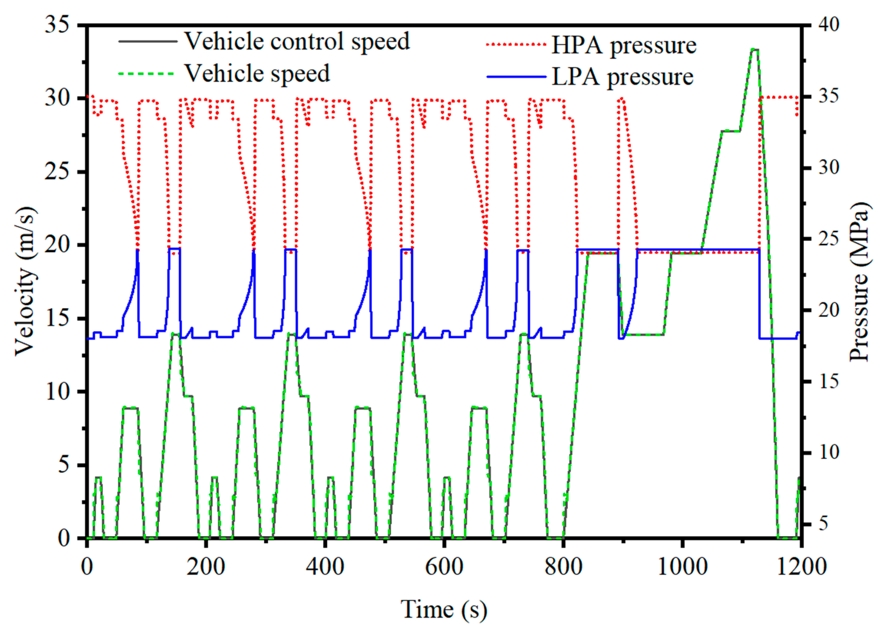
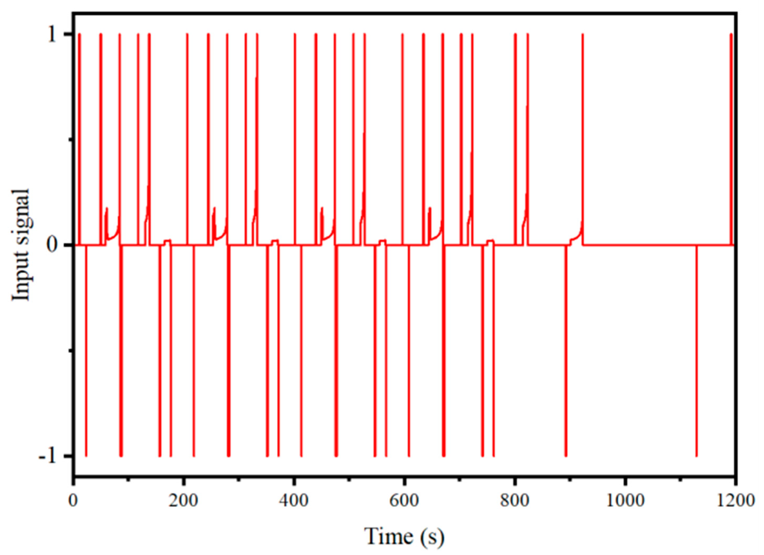
6.2. Results and Analysis of Validation

Figure 15 shows the speed and pressure curves. Figure 16 shows the swashplate signal curve. After the joint verification of AMESim/Simulink, the speed curve of the MEH-DCDS can follow the control vehicle speed well, as shown in the figure. The curves basically overlap, and there is no serious out-of-curve problem. At the same time, the pressure of the high- and low-pressure accumulators can be changed continuously with a change in vehicle speed. The swashplate signal is positive when the vehicle speed is rising. At this time, the HPA pressure goes down and the LPA pressure goes up. When the speed is decreasing, the swashplate signal is negative. The HPA pressure goes up and the LPA pressure goes down. This is basically in line with the original design concept.
Figure 17 shows the curves of the battery SOC consumption rate for the MEH-DCDS and EV. It can be seen from the graph that the battery SOC remaining for the MEH-DCDS is 94.7363% and the battery SOC remaining for the EV is 93.3931%, with a 20.33% reduction in the energy consumption rate. Figure 18 shows the mileage comparison between the MEH-DCDS and the EV under the NEDC cycle condition. It can be seen that the vehicle has a mileage of 11.0041 km when driven by hydraulic power, while the EV has a mileage of 10.9584 km, an increase of 45.7 m compared to the EV.

7. Conclusions

A new type of electro-hydraulic power coupler (MEH-DCDS) is proposed. It integrates the traditional permanent magnet rotating motor with the swashplate axial piston pump/motor, which can realize the mutual conversion of electrical energy, mechanical energy, and hydraulic energy. This article explains its working principle and advantages. At the same time, its key components are modeled to complete the structural realization of the vehicle model. According to the MEH-DCDS design principle, the different modes of operation of a vehicle are classified. The energy flow in different driving modes is not the same, so the driving energy of the vehicle under different operating conditions is studied. Based on this principle, an energy management strategy based on different operating conditions is designed. The results of the validation can demonstrate the feasibility of the system.
Based on the AMESim software platform, the starting acceleration performance of the MEH-DCDS and purely electric drive system is simulated and analyzed. The results show that the start time of the purely electric drive system is 7.58 s, while that of the MEH-DCDS is 4.52 s, and the starting performance is improved by 40.37%.
Based on the dynamic model of the MEH-DCDS, a control method combining real-time feedback of hydraulic power output torque and PID control is proposed. The output torque is calculated by a formula and fed back to the input signal. After the PID adjustment, the oil drainage of the MEH-DCDS is greatly reduced, and the starting time of the vehicle is shortened by 1.04 s, while the starting time is shortened by 1.04 s and the acceleration performance is improved by 23.01%, which greatly improves the power performance of MEH-DCDS.
The dynamic performance of the MEH-DCDS was verified by the AMESim model. The system is now integrated into the whole vehicle. The dynamic performance of the MEH-DCDS under cycle conditions was verified by using AMESim to build a model of the whole vehicle, Simulink software to build a control strategy, and co-simulation methods to verify the dynamic performance of the MEH-DCDS under cycle conditions. The vehicle runs for one NEDC certification cycle after loading the MEH-DCDS, and the MEH-DCDS is able to follow the control vehicle speed well. The SOC consumption rate was reduced by 20.33% compared to a purely electric vehicle, and the MEH-DCDS has an increased range of 45.7 m compared to the EV. Finally, the proposed new structure is proven to be feasible in terms of dynamics and vehicle application.
Ultimately, the new structure proposed in this paper can not only improve the vehicle’s dynamic performance, but also improve its energy efficiency. After applying the system to the vehicle, it is verified that the simulation can significantly reduce the SOC consumption and increase the mileage of the vehicle. This will provide a good basis for further research ideas pertaining to the study of electro-hydraulic hybrid power systems.

Author Contributions

Conceptualization, Z.M.; Data curation, J.Y.; Formal analysis, J.Y. and J.H.; Methodology, T.Z., H.Z., J.H. and Z.M.; Resources, J.Y., T.Z., H.Z. and J.H.; Writing – original draft, J.Y.; Writing—review & editing, J.Y. and J.H. All authors have read and agreed to the published version of the manuscript.

Funding

This research was funded by the National Natural Science Foundation of China, grant number 52075278, and Municipal Livelihood Science and Technology Project of Qingdao, grant number 19-6-1-92-nsh.

Conflicts of Interest

The authors declare no conflict of interest.

References

  1. Hong, J.C.; Wang, Z.P.; Zhang, T.Z. Research on Performance Simulation of Load Isolation Pure Electric Driving Vehicles. Energy Procedia 2016, 104, 544–549. [Google Scholar] [CrossRef]
  2. Zhang, N.; Chen, X.; Yu, M. Materials chemistry for rechargeable zinc-ion batteries. Chen. Soc. Rev. 2020, 49, 4203–4219. [Google Scholar] [CrossRef] [PubMed]
  3. Lu, L.; Han, X.; Li, J.; Hua, J.; Ouyang, M. A review on the key issues for lithium-ion battery management in Electric Vehicles. J. Power Sources 2013, 226, 272–288. [Google Scholar] [CrossRef]
  4. Liu, K.; Luo, S.; Zhou, J. En-Route Battery Management and a Mixed Network Equilibrium Problem Based on Electric Vehicle Drivers’ En-Route Recharging Behaviors. Energies 2020, 13, 16. [Google Scholar] [CrossRef]
  5. Wu, Y.; Jiang, X.H.; Xie, J.Y. The reasons of rapid decline in cycle life of Li-ion battery. Battery Bimon. 2009, 39, 206–207. [Google Scholar]
  6. Deng, L.Z.; Wu, F.; Gao, X.G.; Wu, W. Development of a LiFePO4-based high power lithium secondary battery for HEVs applications. Rare Met. 2014, 39, 1457–1463. [Google Scholar] [CrossRef]
  7. Guo, W.; Cong, Z.; Guo, Z.; Chang, C.Y.; Pu, X. Dendrite-free Zn anode with dual channel 3D porous frameworks for rechargeable Zn batteries. Energy Storage Mater. 2020, 30, 104–112. [Google Scholar] [CrossRef]
  8. Wang, L.; Wang, X.; Yang, W. Optimal design of electric vehicle battery recycling network—From the perspective of electric vehicle manufacturers. Appl. Energy 2020, 275, 115328. [Google Scholar] [CrossRef]
  9. Zhao, K.G.; Liang, Z.H.; Huang, Y.J.; Wang, H.; Khajepour, A.; Zhen, Y.K. Research on a Novel Hydraulic/Electric Synergy Bus. Energies 2017, 11, 34. [Google Scholar] [CrossRef] [Green Version]
  10. Fiala, S.; Bubak, A.; Novotny, L. Control of hybrid electric-hydraulic drive for vertical feed axes of machine tools. MM Sci. J. 2019, 2019, 3228–3235. [Google Scholar] [CrossRef]
  11. Sun, H.; Jing, J.Q. Research on the System Configuration and Energy Control Strategy for Parallel Hydraulic Hybrid Loader. Automat. Constr. 2010, 19, 213–220. [Google Scholar]
  12. Pugi, L.; Pagliai, M.; Nocentini, A.; Lutzemberger, G.; Pretto, A. Design of a hydraulic servo-actuation fed by a regenerative braking system. Appl. Energy 2017, 187, 96–115. [Google Scholar] [CrossRef]
  13. Wang, J. Hierarchical Model Predictive Control for Hydraulic Hybrid Powertrain of a Construction Vehicle. Appl. Sci. 2020, 10, 745. [Google Scholar] [CrossRef] [Green Version]
  14. Pretto, A.; Pugi, L.; Pugi, L.; Giglioli, M.; Berzi, L.; Locorotondo, E. Simulation and design of a kit for the electrification of a light tricycle truck. Int. J. Heavy Veh. Syst. 2020, 27, 278–302. [Google Scholar] [CrossRef]
  15. Zhou, S.; Walker, P.; Tian, Y.; Zhang, N. Mode switching analysis and control for a parallel hydraulic hybrid vehicle. Veh. Syst. Dyn. 2020. [Google Scholar] [CrossRef]
  16. Niu, G.; Shang, F.; Krishnamurthy, M.; Garcia, J.M. Design and Analysis of an Electric Hydraulic Hybrid Powertrain in Electric Vehicles. IEEE Transp. Electr. 2016, 3, 48–57. [Google Scholar] [CrossRef]
  17. Hwang, H.Y.; Lan, T.S.; Chen, J.S. Optimization and Application for Hydraulic Electric Hybrid Vehicle. Energies 2020, 13, 322. [Google Scholar] [CrossRef] [Green Version]
  18. Sprengel, M.; Ivantysynova, M. Recent Developments in a Novel Blended Hydraulic Hybrid Transmission. SAE Tech. Pap. 2014, 2014. [Google Scholar] [CrossRef]
  19. Niu, G.; Shang, F.; Krishnamurthy, M. Evaluation and selection of accumulator size in electric-hydraulic hybrid (EH2) powertrain. ITEC 2016. [Google Scholar] [CrossRef]
  20. Midgley, W.; Cathcart, C.D. Modelling of hydraulic regenerative braking systems for heavy vehicles. Proc. Inst. Mech. Eng. 2013, 227, 1072–1084. [Google Scholar] [CrossRef]
  21. Wang, H.; Wang, Q. Parameter Matching and Control of Series Hybrid Hydraulic Excavator based on Electro-hydraulic. Composite Energy Storage. IEEE Access 2020, 8, 111899–111912. [Google Scholar] [CrossRef]
  22. Zhou, H.C.; Xu, Z.P.; Liu, L.; Liu, D.; Zhang, L.L. Design and validation of a novel hydraulic hybrid vehicle with wheel motors. Sci. Prog. 2019, 103, 003685041987802. [Google Scholar] [CrossRef] [PubMed]
  23. Nadeau, J.; Micheau, P.; Boisvert, M. Collaborative control of a dual electro-hydraulic regenerative brake system for a rear-wheel-drive electric vehicle. Proc. Inst. Mech. Eng. 2018, 233, 1035–1046. [Google Scholar] [CrossRef]
  24. Zhao, W.Z.; Zhou, X.C.; Wang, C.Y.; Luan, Z.K. Energy analysis and optimization design of vehicle electro-hydraulic compound steering system. Appl. Energy 2019, 255, 113713. [Google Scholar] [CrossRef]
  25. Liu, H.L.; Chen, G.P.; Xie, C.X.; Li, D.F.; Wang, J.W.; Li, S. Research on energy-saving characteristics of battery-powered electric-hydrostatic hydraulic hybrid rail vehicles. Energy 2020, 205, 118079. [Google Scholar] [CrossRef]
  26. Li, J.S.; Zhao, J.Y.; Zhang, X.C. A Novel Energy Recovery System Integrating Flywheel and Flow Regeneration for a Hydraulic Excavator Boom System. Energies 2020, 13, 315. [Google Scholar] [CrossRef] [Green Version]
  27. Hong, J.C.; Wang, Z.P.; Zhang, T.Z.; Yin, H.X.; Zhang, H.X.; Huo, W.; Zhang, Y.; Li, Y. Research on integration simulation and balance control of a novel load isolated pure electric driving system. Energy 2019, 189, 116220. [Google Scholar] [CrossRef]
  28. Wu, W.; Di, C.; Hu, J. Dynamics of a hydraulic-transformer-controlled hydraulic motor system for automobiles. Proc. Inst. Mech. Eng. 2016, 230, 229–239. [Google Scholar] [CrossRef]
  29. Golman, R.; Bhatia, S.; Kane, P.B. The dual accumulator model of strategic deliberation and decision making. Psychol. Rev. 2020, 127, 477–504. [Google Scholar] [CrossRef]
  30. Xin, Y.F.; Zhang, T.Z.; Zhang, H.X.; Zhao, Q.H.; Zheng, J.; Wang, C.C. Fuzzy Logic Optimization of Composite Brake Control Strategy for Load-Isolated Electric Bus. Math. Probl. Eng. 2019, 2019, 9735368. [Google Scholar] [CrossRef]
  31. Yang, Y.; Zhong, Z.; Wang, F.; Fu, C.Y.; Liao, J.Z. Real-time Energy Management Strategy for Oil-Electric-Liquid Hybrid System Based on Lowest Instantaneous Energy Consumption Cost. Energies 2020, 13, 4. [Google Scholar] [CrossRef] [Green Version]
  32. Zhou, S.; Walker, P.; Zhang, N. Parametric design and regenerative braking control of a parallel hydraulic hybrid vehicle. Mech. Mach. Theory 2020, 146, 103714. [Google Scholar] [CrossRef]
Figure 1. Structure of the mechanical–electric–hydraulic dynamic coupling drive system (MEH-DCDS).
Energies 13 06279 g001
Figure 2. Schematic diagram of the battery pack.
Energies 13 06279 g002
Figure 3. Diagram of the different modes of operation of the motor/generator.
Energies 13 06279 g003
Figure 4. Working mode diagram of the MEH-DCDS.
Energies 13 06279 g004
Figure 5. Energy management strategies of the MEH-DCDS.
Energies 13 06279 g005
Figure 6. MEH-DCDS model constructed using the AMESim software.
Energies 13 06279 g006
Figure 7. Internal structure of the MEH-DCDS: (a) is the MEH-DCDS model, and (b) is the MEH-DCDS model under PID control.
Energies 13 06279 g007
Figure 8. Diagram of the switch signal.
Energies 13 06279 g008
Figure 9. Diagram of the vehicle speed comparison.
Energies 13 06279 g009
Figure 10. Diagram of the output torque.
Energies 13 06279 g010
Figure 11. Diagrams of the pressure and gas changes of the accumulator. (a) is the curve of oil pressure in high pressure accumulator, (b) is the curve of oil pressure in low pressure accumulator, (c) is the curve of gas volume in high pressure accumulator, and (d) is the curve of gas volume in low pressure accumulator.
Energies 13 06279 g011
Figure 12. Diagram of the vehicle speed under different controls.
Energies 13 06279 g012
Figure 13. Diagrams of the oil pressure and gas volume of the MEH-DCDS with and without PID control. (a) is the comparison chart of oil pressure in high pressure accumulator, (b) is the comparison chart of oil pressure in low pressure accumulator, (c) is the comparison chart of gas volume in high pressure accumulator, and (d) is the comparison chart of gas volume in low pressure accumulator.
Energies 13 06279 g013
Figure 14. Model drawing of the whole car.
Energies 13 06279 g014
Figure 15. Diagram of the speed and pressure curves.
Energies 13 06279 g015
Figure 16. Diagram of the swashplate signal curve.
Energies 13 06279 g016
Figure 17. Comparison of the state-of-charge (SOC) consumption rates.
Energies 13 06279 g017
Figure 18. Comparison of mileage.
Energies 13 06279 g018
Table 1. Battery pack parameters.
Battery Pack ParametersValueUnit
Voltage of the battery pack310V
Maximum power of the battery pack35kw
Battery pack capacity65Ah
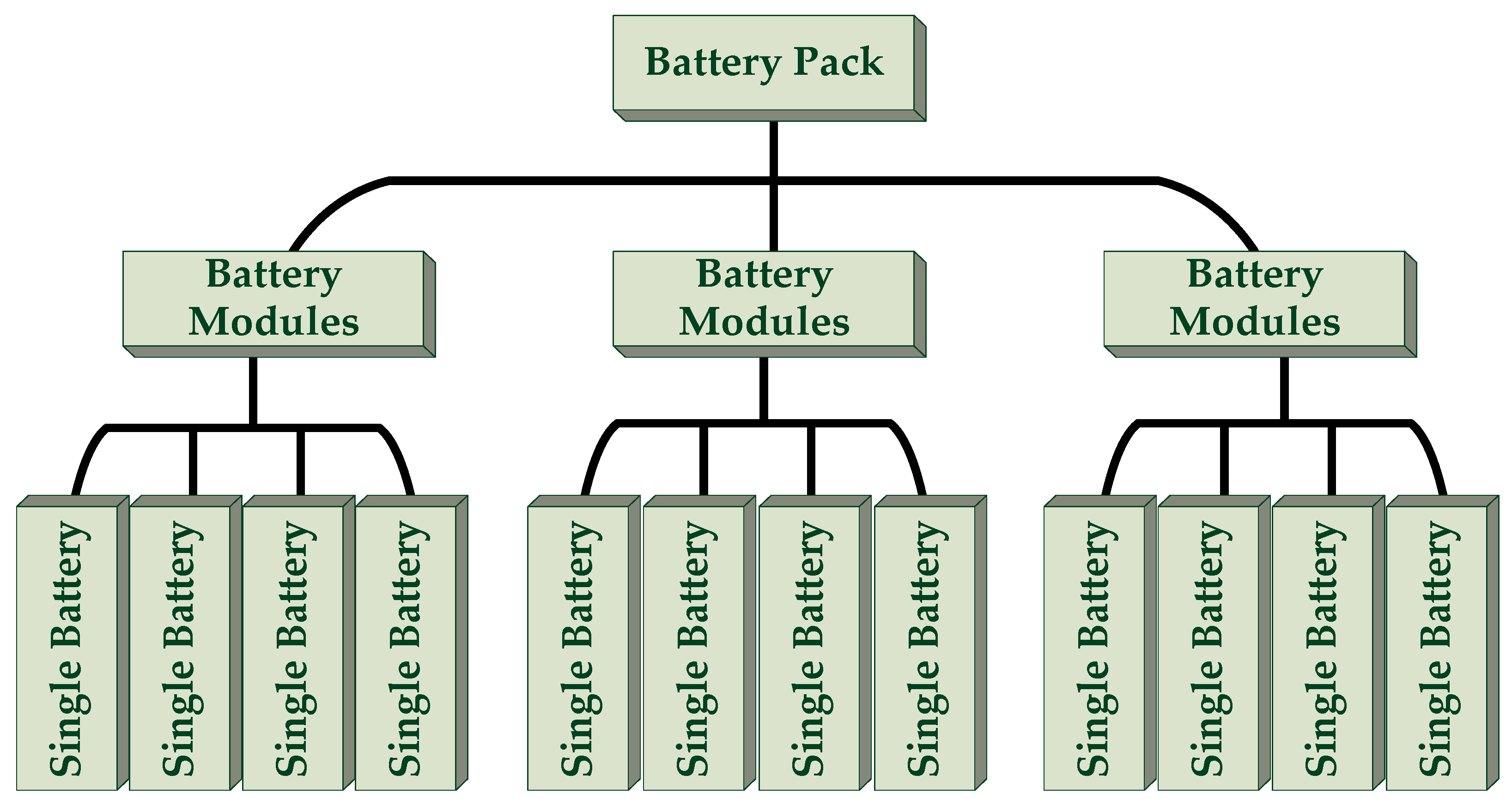
Number of battery modules connected in parallel1None
Number of battery modules in series6None
Number of individual cells in series per module40None
Table 2. Working modes of the MEH-DCDS.
Working ModePower SourceDiagram of Energy Flow
MotorHydraulic Pump/Motor
Starting modeHydraulic motor Energies 13 06279 i001
Acceleration/climbing modeMotorHydraulic motor Energies 13 06279 i002
Constant speed modeMotor Energies 13 06279 i003
Braking modeGeneratorHydraulic pump Energies 13 06279 i004
Idle modeMotorHydraulic pump Energies 13 06279 i005
Table 3. Basic parameters of the MEH-DCDS.
ComponentsParametersValue
Basic parameters of the vehicleLoaded mass (m)1206 kg
Frontal area (A)2.28 m2
Rolling resistance coefficient (f)0.0135
Coefficient of air resistance (CD)0.32
Wheel width (R)290 mm
Transmission efficiency (η)0.85
High pressure accumulatorWork pressure (P1)24–35 MPa
Volume (V)35 L
Low pressure accumulatorWork pressure (P2)6–22 MPa
Volume (V)35 L
Secondary componentDisplacement (Vp)30 mL·r−1
MotorRated power (Pe)32 kW
Publisher’s Note: MDPI stays neutral with regard to jurisdictional claims in published maps and institutional affiliations.

