Abstract
The power quality of electrical grids is becoming an important issue worldwide. The electrical grid has to deliver sinusoidal voltages and currents without frequency or amplitude variations. However, the connection of non-linear loads generates harmonics that degrade the grid quality. The presence of harmonics in the load currents has many negative consequences and can distort the voltage waveform at the point of common coupling (PCC). Thus, it is essential to mitigate the harmonics in order to maintain a suitable grid quality. This is a shared responsibility between energy suppliers, manufacturers of electric and electronic equipment, and users. In this context, this work presents, for each stakeholder, a comprehensive analysis of their responsibilities and the standards that they should meet. Additionally, this paper reviews the most common types of filters used to comply with the applicable standards in industrial applications. Finally, in order to prove that active power filters allow maintaining good power quality in all types of grid, commercially available active power filters were installed in three different grids contexts: an office building, a factory, and a stadium with a large number of LEDs. The experimental results obtained were used to evaluate the impact of active filters on grid quality. This review would help users to overcome their grid distortion problems.
1. Introduction
Electricity consumption has been continuously increasing since 1990 [1]. The International Energy Agency estimates that in 2017 the electricity demand was 27% higher than in 2009. This increment has not been uniform worldwide. In the European Union and the USA, electricity consumption has remained steady from 2009 [1,2,3], while in China and India the demand has grown [1].
The major part of the electrical energy is consumed in industry, followed by households. In Figure 1, the electricity final electrical consumption by sector is shown for different world regions [1]. In all the regions, light and heavy industries represent more than 50% of the electricity consumption. The only exception is the Middle East, where the industry only represents around 47% of the demand.
Figure 1.
Electricity final consumption by sectors and regions.
Electrical energy, like any product, has to fulfill quality requirements. Electrical and electronic equipment need a quality electrical supply in order to work properly; this equipment demands sinusoidal voltages and currents without variations in the frequency, the amplitude, or the waveform. These distortions can cause malfunctions, reduce the service life, and decrease performance [4,5,6]. However, it is usually the equipment itself in a facility, such as power electronics devices with non-linear characteristics [4,7], that distorts the electrical supply. Some examples of non-linear loads are rotating machines, computers, lighting, lifts [6], and electrical vehicle chargers [8]. 
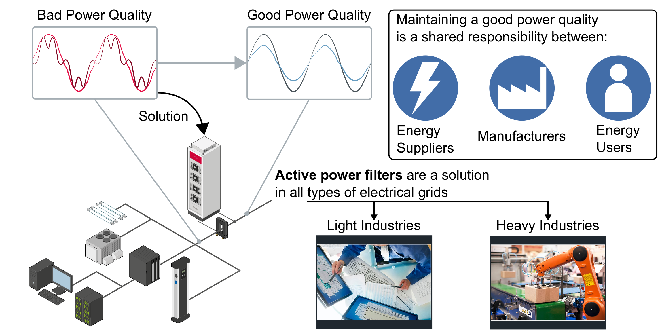
Figure 2 illustrates some current waveforms produced by common non-linear loads [9].
Figure 2.
Typical current waveforms [9].
One of the most important contributors to bad power quality is the presence of harmonics on the electrical grid. The connection of non-linear loads causes harmonic currents to flow in the power system [10,11,12], which can distort the supply voltage waveform at the point of common coupling (PCC) because of the source impedance [13]. An important consequence of harmonics is that they can cause damage to loads connected to the PCC in different ways. In conductors, current harmonics increase the Joule effect losses [13]. Harmonics also increase the losses in the copper windings and core of a transformer, causing a temperature increase and reducing the unit’s lifespan. In electrical motors, harmonics can reduce the useful torque and decrease performance. Harmonics can cause unexpected activation of protective devices such as circuit breakers [6,13]. The presence of harmonics is also undesirable for communication systems. Depending on the frequency, the degree of coupling, and the equipment sensitivity, certain harmonics can introduce noise or interference into communications circuits [14]. Even more critical effects can occur; harmonics can propagate through connected electrical subgrids, create a failure through interdependencies, and result in blackouts [15].
All these effects have an economic impact. Table 1 lists the main harmonics-generated problems that can cause unexpected losses in industry [16]. According to [17], the economic impact of poor power quality in European industry is more than 150 billion. Harmonics also produce additional costs in domestic environments. In Spain, their presence causes additional annual costs of up to 5 million in the residential sector [7], while in Brazil, this economic impact exceeds US$841 million [18].
Table 1.
Problems caused by harmonics.
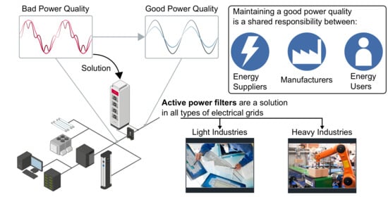
In order to avoid these problems, and to improve grid quality, it is usual to use filters to mitigate distortions propagated through the PCC; active power filters (APFs) are an attractive solution. A parallel (shunt-connected) APF can compensate for current harmonics, reactive power, and unbalanced currents [19,20,21]. Figure 3 shows the connection of APFs at PCCs to improve grid quality [6]. In this figure, we can differentiate three levels. Level 1 is the PCC, where the majority of APFs would be connected, since this is the point with the most distortion. In level 2, the power supply consumption of some loads is monitored and analyzed. Furthermore, voltages and currents are filtered to supply specific loads such as electric vehicle chargers, lighting and, uninterruptible power supplies. Illumination is a primary source of harmonics [17], so the figure depicts an APF compensating the harmonics of these loads. Finally, in level 3, there are the remaining loads connected to the grid. Within this level, there is a data processing center, another significant source of disturbances [17], and an APF is required to compensate its harmonics.
Figure 3.
Application type with active power filters (APFs) at point of common coupling (PCC) and next to some loads.
Maintaining good power quality, including compensating for harmonics, is not the exclusive responsibility of users. Energy suppliers and manufacturers of electrical and electronic equipment also have duties to maintain power quality [10]. In general, energy suppliers have to maintain voltage quality at the supply points [22], while manufacturers should design equipment that does not degrade the current quality or cause flicker or voltage variations [23]. Moreover, users are responsible for maintaining the power quality high enough in their installations to not worsen that in the electricity supply or affect other users [10]. Many jurisdictions have regulations, such as the standards IEEE 519-2014 [10] and EN 50160 [22] and the Electromagnetic Compatibility Directive (2014/30/EU) [23], that impose requirements to achieve a suitable power quality. Each stakeholder should comply with their applicable regulations for maintaining good grid power quality and also to avoid legal problems.
The literature on power quality focuses on different topics. Some authors introduce techniques for improving the power quality of distribution networks, such as using static compensators [24], distributed energy storage systems [25], and hybrid power filters for unbalanced low-voltage grids [26]. Others focus on improving power quality in grids containing unbalanced systems. The majority of these articles introduce novel control techniques using series hybrid power filters [27], shunt active filters [28], or unified power quality conditioners [29]. In [30], there is an extensive review of the control algorithms of APFs for different grids, including the unbalanced ones. A significant trend is the detection of distortions; the most important techniques for identifying the harmonics of a distorted signal are analyzed in [31]; in [15], there is a review of existing techniques to automatically identify the most common power quality disturbances, such as voltage sags, harmonics, and frequency deviations. Moreover, a novel method for harmonic extraction in unbalanced grids is presented in [32]. Because artificial intelligence is an important trend, implementing neural networks to classify grid disturbances was proposed in [33,34]. Power quality is also critical in microgrids, and some works have addressed this issue. A centralized control algorithm for selective harmonic compensation, which takes advantage of the use of distributed electronic converters, is proposed in [35]. In [36], the management of the microgrid-APF resources is optimized from an economic point of view. Some papers compare the standards for grid quality or efficiency in, for example, DC grids [37] or the European Union [38]. However, few papers show the effect of proposed strategies in real grids. In [39], the authors proposed an open unified power quality conditioner and installed it in an actual low voltage grid in Italy. Another work studied different topologies of passive filters and simulated their impact using real data from an industrial plant [40]. In [41], the authors propose a new passive filter design method. The work uses data from a petrochemical factory located in Egypt to assess the effectiveness of the proposed method. Another work uses data from a microgrid located in Canada to analyze if an APF can improve its power quality [42]. Finally, in [12], the authors used data collected from two different industrial environments to simulate the effect of passive and active filters on the grid quality.
Previous studies briefly mention some power quality standards. Thus, there are no extensive examinations on this subject. It is important to define the obligation, applicability, and requirements of these standards since they are fundamental for maintaining a good grid power quality.
There are many APFs topologies, but past comparisons between them only include specific topologies, such as two-level converters. Comprehensive comparisons between the main APF topologies are necessary to conclude the optimum use of each topology.
Works that validate their proposals on real grids are scarce. Electrical grids can greatly differ from one application to another; for instance, the grid parameters of a car factory will not be the same as the ones of a hotel or a theater. Even grids within the same application may have different causes for their power quality problems [43]. Hence, it is desirable to study as many grids as possible. Analyzing a high number of grids would allow the authors to validate the suggested solutions in different environments and, thus, providing power quality solutions to a larger audience.
The present work reviews the trends in power quality and standards for all types of industrial grids. This study presents the following novelties:
- International power quality standards. The paper provides a comprehensive analysis of the responsibilities of all stakeholders regarding power quality. There is an examination of the power quality requirements imposed by international standards.
- Solutions for improving power quality. This review explores how suppliers, manufacturers, and users can comply with their applicable regulations. Power filters are a usual solution for improving power quality in industrial grids. Hence, this study compares the main types of filters: passive, active, and hybrid, to determine when it can be more effective to use one particular type. Furthermore, the paper includes an in-depth comparison between the main topologies of shunt active power filters and a discussion about their uses and their positive and negative aspects. Moreover, the most recent APF topologies are briefly introduced.
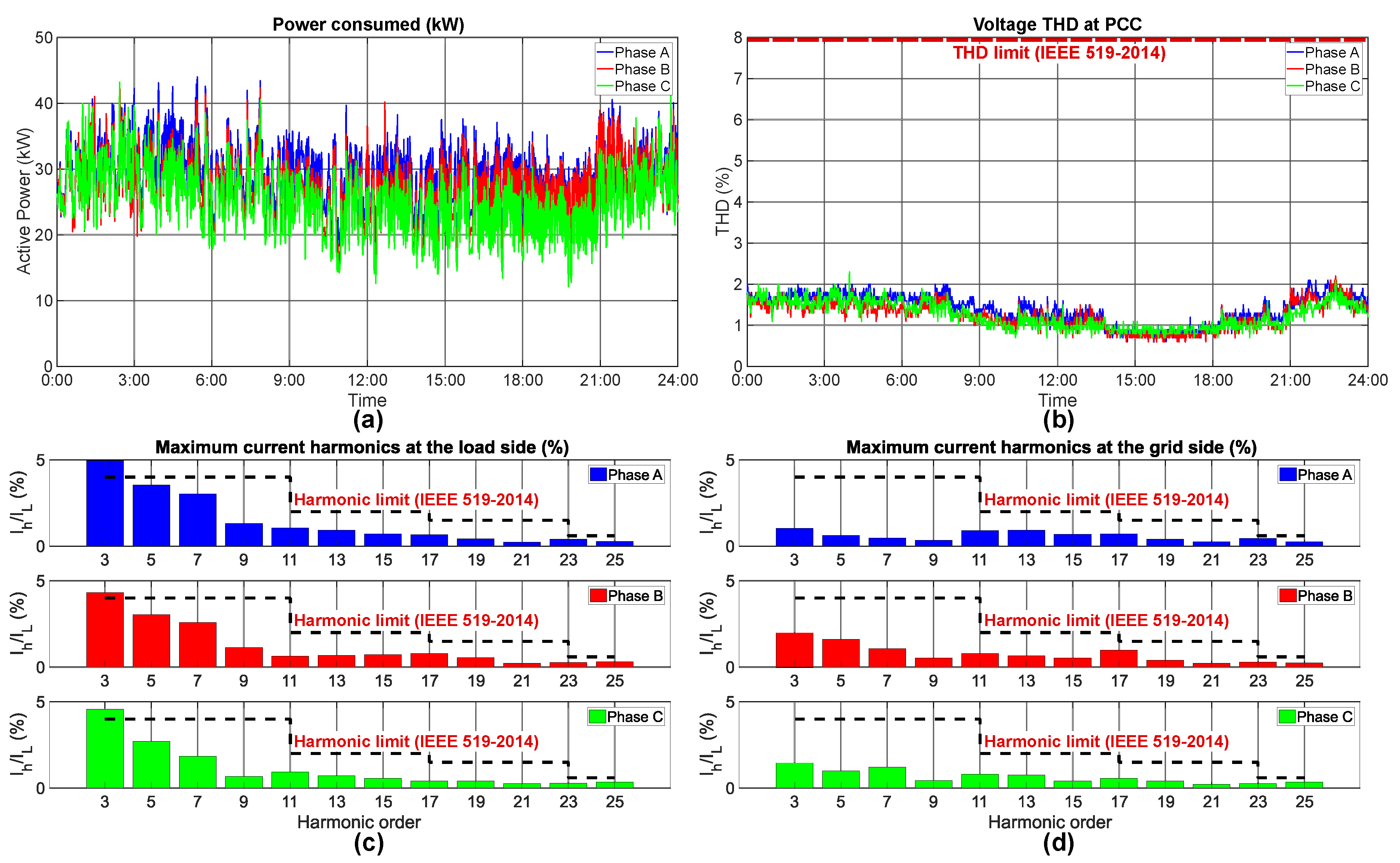
- Effectiveness in real grids. The present work aims to show how shunt active power filters allow achieving a suitable grid quality in all types of industrial grids. We have installed active power filters in three different facilities: an office building, a capacitor-manufacturing factory, and a stadium. In these locations, we measured the harmonic distortion and verified that the APFs greatly decrease the harmonic content.
Table 2 compares the present review with previous power quality papers. Works whose scope is other power filters, such as passive filters, are excluded from this table. Control and modulation techniques are out of the scope of this paper, so these topics are excluded from Table 2.
Table 2.
Scope of previous power quality works.
This paper is structured as follows: Section 2 explains the responsibilities regarding grid quality of energy suppliers, manufacturers of equipment, and users. Moreover, it examines the standards to which they should or must comply. Section 3 describes and compares the different types of filter. Section 4 shows the behavior of different real grids and their distortion levels at the PCC. This section also shows the impact of APFs on improving grid quality. Finally, Section 5 outlines conclusions from this paper.
2. Responsibility of Grid Quality
As stated in Section 1, maintaining a good power quality in a grid is a shared responsibility between the energy suppliers, the manufacturers of electric and electronic equipment, and users [6,10]. However, the obligations of the parties are not the same. In the following subsections, we explore the responsibilities of each party in relation to the details of the standards that they should or must comply.
2.1. Energy Suppliers
The suppliers are the distribution companies who provide electricity via a distribution system [22]; they are responsible for ensuring a quality of power that is suitable for users [6,48].
There are no international standards specifying the obligations of suppliers, but there are groups of countries with non-mandatory standards that serve as guides. In the European Union, the standard that details the requirements for a supplier is EN 50160 [22]. Some countries, such as Germany and Poland, complement this standard using their own national standards [48].
Briefly, for a low voltage grid, EN 50160 imposes the following requirements at the point of delivery to a user [22]:
- The frequency variations must not exceed of +4%/−6% of the rated frequency;
- The voltage variations must not exceed of ±10% of the rated voltage;
- The negative sequence voltage must not be grater than 2% of the positive sequence voltage;
- The total harmonic distortion voltage (THD) must be less than or equal to 8%. The THD is calculated using Equation (1) [22,48];
- The limits for voltage harmonics are given in Table 3.
Table 3. Maximum harmonic voltage distortion at supply points (up to harmonic order 25) [22].
The requirements of the standard for suppliers are not absolute [48]; they are intended for normal operating conditions. Under abnormal conditions such as extreme climatic conditions or during strikes, the standard is not applicable [22]. Furthermore, many suppliers interpret standard EN 50160 as informative only and do not accept responsibility if the recommendations are not met [48].
2.2. Manufacturers of Electric and Electronic Equipment
Manufacturers must guarantee that their products do not produce a level of electromagnetic interference that will cause malfunctions in other equipment [23]. Further, their equipment must have sufficient immunity to expected electromagnetic disturbances [23].
The easiest way to ensure compliance with these requirements is to design the equipment according to standards [23]. However, each country has different standards, so some organizations coordinate national standards with international standards [49]. Examples of these organizations are the European Committee for Electrotechnical Standardization (CENELEC) and the American National Standards Institute (ANSI).
Manufacturers should select the applicable standards [23] according to the equipment characteristics and the intended environment of use; they differ between industrial, light-industry, or residential environments. Table 4 shows the different generic standards that cover the emissions and immunity of equipment [50]. Note that the standards cited are the European standards but are equivalent to the international standards of the International Electrotechnical Commission (IEC).
Table 4.
Harmonized standards for emission and immunity.
The main differences between the residential and industrial standards are in the limits of emission and the level of immunity. In domestic environments, there are no important electromagnetic disturbances created; consequently, emissions from domestic equipment are strictly limited [51]. In accord with this situation, domestic equipment can be less immune to electromagnetic disturbances [52]. The situation is reversed in industrial environments: there are more electromagnetic disturbances, and the equipment must therefore have a high degree of immunity, but a higher level of emissions is allowed [53,54].
Apart from the emission and immunity standards, there are other standards within the scope of electromagnetic compatibility. Table 5 enumerates the harmonized standards that cover the voltage perturbations and harmonic currents produced by equipment connected to the grid [50]. The place of use of the equipment is not relevant in these standards but, instead, it is the rated current of the equipment.
Table 5.
Harmonized standards for disturbances in voltage and current.
The standards EN 61000-3-3 [55] and EN 61000-3-2 [56] apply to equipment whose rated input current is 16 A or less. In comparison, standards EN 61000-3-11 [57] and EN 61000-3-12 [58] are for equipment whose input current is between 16 and 75 A. These are European standards but they are equivalent to international IEC standards.
When equipment complies with all the mandatory requirements of a territory, a manufacturer is permitted to sell it within that territory [23]. Manufacturers have to mark equipment with the appropriate certification mark [23]. Figure 4 shows the most important marks.
Figure 4.
Certification marks for: (a) China; (b) European Union; (c) Eurasian Customs Union; (d) United States of America and Canada.
2.3. Energy Users
Users consume the energy provided by suppliers. Users are required to keep the grid power quality high enough to avoid problems within their own installations and not cause harm to other users [6]. Furthermore, suppliers may check the consumption of users and may penalize those who exceed certain distortion limits [6].
Users may use compliance with the requirements in standard IEEE 519-2014 [10] as an indication of good grid-oriented power quality for their installations. This standard limits the distortion of voltage and current at the PCC.
In brief, IEEE 519-2014 limits the distortions at the PCC of low voltage grids as follows [10]:
- The THD of the voltage must not be greater than 8%. The THD has to be calculated considering harmonic components up to the 50th.
- The voltage must not have harmonics with a relative amplitude greater than 5%.
- The maximum current distortion is limited according to Table 6. The TDD is calculated using Equation (2) [10].
Table 6. Maximum harmonic current distortion in percent of [10].
When the distortion on the PCC exceeds the limits imposed by the supplier, users have to adopt corrective measures [6]. One of the most used solutions is the installation of a filter: passive, hybrid, or active [6]. In the next section, we describe the different types of filters and we discuss their uses and their positive and negative aspects.
3. Types of Filters
In Section 2, we stated that users have to maintain good grid power quality at the PCC, and should take measures to mitigate current harmonics. Essentially, three types of filter are available to compensate for these harmonics: passive filters (PFs), active power filters (APFs), and hybrid power filters (HPFs). Table 7 summarizes the main characteristics of each type of filter and Figure 5 distinguishes these three types of filters by their circuit design.
Table 7.
Comparison of the main features of passive filters, active power filters, and hybrid filters for improving grid quality.
Figure 5.
Filter topologies: (a) passive filter (PF); (b) active power filter (APF); (c) hybrid power filter (HPF).
Passive filters are one of the most economical ways to mitigate harmonics [59,60]. There are many types of passive filters, but the most used are the L and the LC [4]. Apart from mitigating harmonics, passive filters are also able to compensate for load reactive power [40]. Passive filters provide a low-impedance path to divert harmonic currents [59,61]; these filters can only compensate for individual harmonics and additional filters are necessary to cover a wide range of harmonics [44]. However, passive filters have significant drawbacks [4,13,44]. The design of passive filters depends on the system impedance. They are susceptible to overloads and can cause resonances with the system. Finally, passive filters are not suitable for variable loads because these loads can detune the filter.
Active power filters do not have the shortcomings of the passive ones. APFs are power converters that inject into the grid, in counter-phase, the same harmonics produced by the loads. The addition of the harmonics in the filter currents synthesizes a sinusoidal waveform at the PCC [6,62]. There are two types of APFs: series-connected and parallel-connected. The first can compensate current harmonics while the second can mitigate voltage harmonics [21]. These types include several sorts of APFs, which are going to be discussed later. The combination of series and shunt APF is known as unified power quality conditioner (UPQF). This type of APF can compensate for voltage and current harmonics, so it is an excellent choice for industries where power quality is critical, such as hospitals and pharmaceutical industries [4]. UPQFs are also an interesting option for low voltage distribution grids [39], the integration of renewable energies [63], and three-phase four-wire grids [64]. All active power filters can compensate harmonics and correct for reactive power [16,62], but only four-wire active power filters can compensate for homopolar currents and avoid an excessive neutral current [20]. Furthermore, APFs can compensate for a wide range of harmonics. Theoretically, they can suppress any harmonic but, in practice, this is limited by their switching-frequency [21]. However, APFs are more expensive than passive filters and the cost increases sharply for high-power applications [60,65]. Hybrid power filters are a cost-effective solution for these cases [65].
A hybrid power filter is a combination of a high-power passive filter and a low-power active filter [66]. Generally, in mitigating current harmonics, the APF cancels the low-order harmonics while the passive filter eliminates the others [44,45]. Nevertheless, there are many HPF topologies, as discussed in [4,44,67,68]. Furthermore, HPFs allow suppressing harmonic resonances in industrial facilities with tuned passive filters installed [69]. As previously mentioned, this type of filter has advantages in high-voltage applications, since the passive filter reduces the voltage stress on the APF switches [45]. In distribution networks, where passive compensation is already installed, the HPF approach becomes an attractive solution for improving grid quality [70]. The main drawback of HPFs is that they require a high number of components, particularly the passive filter. However, some works proposed HPFs based on two-leg converters to reduce the number of components [71]. The HPF passive filter is always connected to the grid, so HPFs may only be suitable for specific loads with a well-known harmonic distortion [45]. Moreover, this passive filter may be bulky and expensive, so some authors proposed using a shunt APFs as an output filter to reduce the size of the passive components [72].
Shunt Active Power Filter Topologies
Active power filters can be classified using different criteria, such as their connection (shunt or series), the converter topology, and the number of wires [45,46]. Shunt connected APFs are the predominant type [21,45,46], but the converter topology differs from one environment to another. For instance, DC–AC converters are the most used in the industry [21,45], while AC–AC converters have a wide acceptance for integrating renewable energy sources to the grid [47].
The number of wires is an important parameter for three-phase shunt APFs. As previously stated, three-wire APFs (Figure 6 and Figure 7) can only compensate for positive and negative sequence currents, while four-wire APFs (Figure 8 and Figure 9) are mandatory for compensating homopolar currents [20,
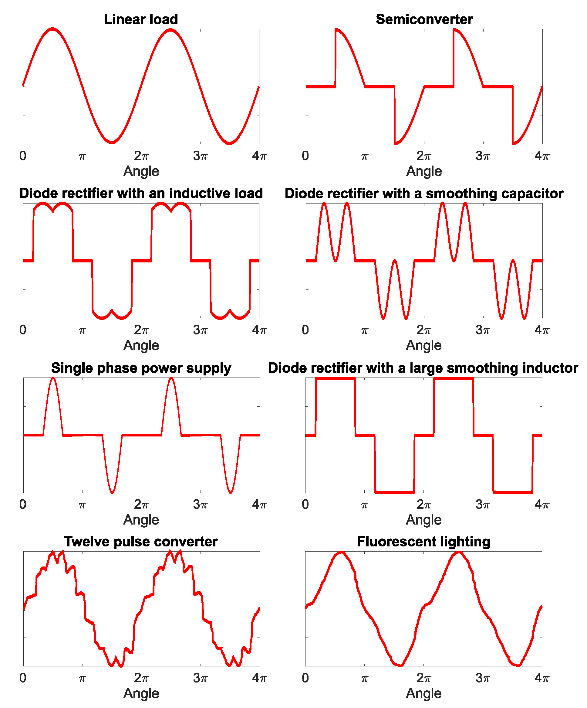
21]. The simplest three-wire APFs are the current source converter (CSC) and the voltage source converter (VSC) [44,45]. Both topologies are two-level converters, but VSCs are preferred because they are cheaper, faster, easier to control, and they can work at higher switching frequencies [44,45,46]. However, CSC may be an interesting choice for certain applications. For instance, in [73], the authors propose using a CSC as a photovoltaic inverter with active filtering functionalities. Figure 6a illustrates a VSC converter, while Figure 6b displays a CSC converter.
Figure 6.
Main topologies of two-level three-wire APFs: (a) voltage source converter (VSC); (b) current source converter (CSC).
Figure 7.
Main topologies of multilevel three-wire APFs: (a) neutral-point-clamped (NPC) converter; (b) flying capacitor (FC) converter; (c) cascaded H-bridge (CHB) converter.
Figure 8.
Main topologies of two-level four-wire APFs: (a) three-leg voltage source converter (3L-VSC); (b) four-leg voltage source converter (4L-VSC); (c) six-leg converter (6L). The optional fourth inductance is drawn with dashed red lines.
Figure 9.
Main topologies of multilevel four-wire APFs: (a) three-leg neutral-point-clamped (3L-NPC); (b) four-leg neutral-point-clamped (4L-NPC); (c) four-leg flying capacitor (4L-FC). The optional fourth inductance is drawn with dashed red lines.
Two-level VSCs are the preferred topology for low voltage applications [74]. However, multilevel converters are attractive for medium and high-power applications because of their advantages [74,75]. First, they can work at higher voltages [74,75]. Second, they can synthesize currents by using more than two voltage levels [75], so they produce lower THD and require smaller output filters. Finally, they have less switching losses and are more efficient than two-level converters [76]. Some multilevel converter topologies have been proposed to work as APFs. These topologies are the neutral-point-clamped (NPC) converter [77], the flying capacitor (FC) converter [78], and the cascaded H-bridge (CHB) converter [79,80]. Figure 7a–c show, respectively, the schematic of a NPC, an FC, and a CHB converter. One of the major problems of these multilevel topologies is the DC-link voltage balancing. On NPC converters, the voltage of the two DC-bus capacitors must be kept at one half of the DC-link voltage. This can be achieved using suitable controllers [81] or appropriate modulation techniques [82,83]. On the FC topology, the voltage of each flying capacitor has to be controlled. However, only a single voltage sensor per phase leg is enough for measuring all the capacitor voltages [84]. Moreover, many modulation techniques provide a natural capacitor voltage balancing [85]. The CHB converters have many DC-links that may become unbalanced when the APF is compensating for harmonics. Some methods have been proposed to solve this problem, such as using a suitable control loop [86] and modifying the modulation frequency [87].
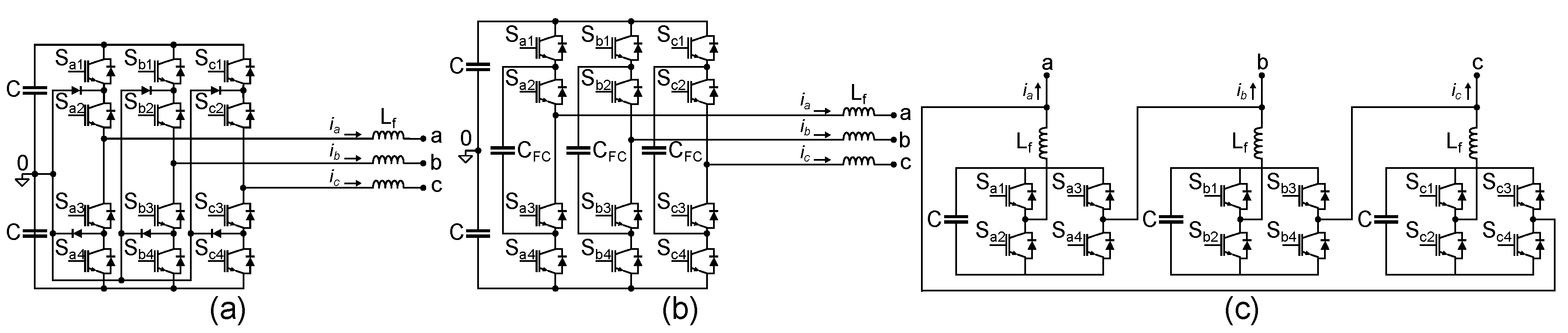
The majority of four-wire APFs are an extension of their three-wire counterparts. In general, there are two methods for connecting the fourth wire [20,88]. The first method is connecting this wire from the neutral point of the DC-bus to the grid neutral. The converters that follow this strategy are known as three-leg converters (3L). The second one is connecting the fourth wire to an additional leg. These converters are called four-leg converters (4L).
Three-leg APFs are cheaper than four-leg converters as they use fewer components. However, connecting the neutral wire to the DC-bus can cause voltage unbalances, so an additional controller or a proper modulation technique is needed to keep the DC capacitors balanced [89,90]. Four-leg converters are more expensive due to their higher number of transistors, but they can have smaller output inductances [88]. Nevertheless, they can have a smaller DC-bus [42] and also compensate the homopolar currents better than the three-leg converters [20,88]. Furthermore, four-leg converters provide better harmonic mitigation than their three-leg counterparts [20]. Among four-wire multilevel APFs, there are two topologies based on NPCs (Figure 9a,b) and another based on an FC (Figure 9c). Both NPC topologies need controlling the unbalances in their DC-bus using complex control or modulation techniques [91]. This problem was addressed in [89] for 3L-NPC converters by proposing a new carrier-based modulation technique without introducing zero-sequence voltages. Other authors presented modulations suitable for the DC-link voltage balancing of multiphase NPC converters [92,93,94]. Moreover, in [95], the authors combined a three-dimensional modulation with offset-injection for eliminating the unbalances in an APF based on a 4L-NPC. The four-leg FC topology does not have this problem, and allows using easier control techniques than the NPC topologies [96]. Finally, to improve the harmonic mitigation, all four-wire APFs can include an inductance in their neutral wire. This inductance allows reducing the grid THD but increases the converter power losses [20].
It also exists a particular topology, the six-leg converter (Figure 8c). This is especially suitable for high power applications [20,97]. Furthermore, this topology may be attractive for the grid connection of fuel cells [98]. The control of six-leg converters is simple, since their phases can compensate harmonics separately [97]. Moreover, these converters require a lower DC-bus voltage than other four-wire topologies [20,97]. However, three coupling transformers are needed for grid connection. In [99], the authors propose a six-leg APF using three separate DC-links, which increases the control complexity in exchange of eliminating the transformers.
Table 8 and Table 9 summarize this section by comparing, respectively, the main shunt two-level and multilevel APF topologies.
Table 8.
Comparison of shunt two-level APF topologies.
Table 9.
Comparison of shunt multilevel APF topologies.
Apart from the above-mentioned topologies (i.e., the most common), many APF topologies have been proposed in the literature. The four-leg split capacitor converter was introduced in [104] and further investigated in [14]. In this topology, the fourth wire is connected to the DC-bus and also to the fourth leg. Recently, a novel control scheme for this type of APF was presented in [105]. To improve the 6L converter, Fabricio et al. presented the four H-bridge topology in [106]. This topology allows working with a low DC-bus voltage and also produces less current THD than the other two-level four-wire topologies. APF topologies with only two legs and four switches are a trend for three-wire systems. Some works propose connecting the third phase to the midpoint of the DC-link [107], while other papers add AC-coupling inductors to enhance the APF compensation capability [108] Another interesting topology is the seven-level APF presented in [109]. The main feature of this converter is its reduced number of components: it only needs six switches and two capacitors per phase. Since wide-bandgap semiconductors are a significant trend in power electronics, some papers are studying their impact on APFs. An asymmetrical three-level APF based on silicon carbide MOSFETs is proposed in [110]. For high-frequency operation, this topology exhibits higher efficiencies than those of conventional three-level converters, such as NPCs.
4. Behavior of Real Grids
In this section, we assess the impact of active power filters on grid power quality for several industrial applications. Active power filters of Figure 10 were installed at the PCC of three different installations, and measurements were made while the APFs were mitigating harmonics.
Figure 10.
Active power filters used in the experiments.
The grids selected for observation have different consumption patterns. The first grid is an office building. It is a light-industrial environment where the harmonic emission is strictly limited [51]. The second grid is a capacitor-manufacturing factory. In this environment, harmonic emissions can be higher than in the first grid [53]. Besides, the factory continuously performs stress tests to its capacitors, which have a significant impact on the grid distortion and power consumption. The last grid is a special case: a football stadium. In a football stadium the power consumption and the distortions at the PCC are steady until there is a match. During a match, the distortion becomes a maximum and can reach critical levels. Table 10 summarizes the performed experiments.
Table 10.
Summary of the performed experiments.
4.1. Office Building
In this experiment, three active power filters were installed at an office building and were required to mitigate harmonics and compensate for the power factor. All the installed filters were of the AFQevo 30 type. This model of APF features a maximum current (rms) of 30 A, per phase, and can supply a maximum power of 20.7 kVA. The main loads of this grid are computers and lighting. These loads are also common in domestic environments, but in the office setting there are more loads connected such as air conditioners and vending machines. Table 11 describes the main parameters of this grid.
Table 11.
Grid parameters: office building.
Figure 11a shows the active power consumed in the office building. From approximately 6:00 h, power consumption increases as the first workers arrive. Most of the company’s workers work from 9:00 to 17:00 h; this period shows elevated power consumption. At 18:00 h, the majority of workers have finished their working day and, power consumption falls. Through the day, power consumption differs between the three phases as a result of connection of single-phase loads.
Figure 11.
Measurements at the office building: (a) active power; (b) voltage THD; (c) maximum current harmonics consumed by the loads; (d) maximum current harmonics at the grid side.
The total harmonic distortion in in voltage at the PCC is shown in Figure 11b. This distortion is highly related to power consumption: the THD increases during the period when more loads are connected to the grid. The THD is always less than 8% and the installation complies with the standard IEEE 519-2014.
Figure 11c displays the maximum value of the individual current harmonics produced by the loads, expressed as a percentage of the maximum demand load current (). The harmonic distortion indicates that there are no homopolar currents: the 3rd harmonic and its multiples have low amplitudes. The main harmonics are the 5th, 7th, 11th, and 13th.
Finally, in Figure 11d we observe the maximum current harmonics at the grid side; these are the harmonics remaining after mitigation. We observe that the amplitudes of all these harmonics are low, and conclude that the filters are working properly in this light-industrial installation.
4.2. Electronic Components Factory
This installation is a factory producing electronic components, principally, capacitors and other passive elements. Production is carried out, while stress and life tests are also performed on the manufactured capacitors. These tests have a significant impact on grid quality and the APFs installed are required to compensate for the distortion produced. Table 12 shows the main parameters of this grid. The APFs have to correct the power factor and suppress the first four odd harmonics (3rd, 5th, 7th, and 9th). The two APFs installed for this experiment were an AFQm 30 and an AFQevo 200, both with four wires. The AFQm 30 is a neutral point clamped converter which can supply a maximum current (rms) of 30 A per phase and can provide a maximum power of 22.9 kVA. The AFQevo 200 is a voltage source converter able to compensate currents of up to 200 A (rms) per phase and a maximum power of 138 kVA. Figure 12 depicts the measurements and results of the experiment.
Table 12.
Grid parameters: factory.
Figure 12.
Measurements at the factory: (a) active power; (b) voltage THD; (c) maximum current harmonics consumed by the loads; (d) maximum current harmonics at the grid side.
Figure 12a shows the active power consumed during a 24 h period at the factory; the consumption remains at a consistent level as a result of the life tests on the capacitors. In Figure 12b we observe the THD of the voltage at the PCC. The THD also remains steady through the day because the main sources of distortion are the life test, and the connection of additional loads during working hours barely affects the total distortion.
In Figure 12c, the maximum harmonics the load demand are shown, and Figure 12d shows the maximum harmonics injected into the grid. In Figure 12c, we observe that loads from factory equipment, such as compressors and lighting, produce a high 3rd harmonic. Other harmonics are also present, such as the 5th, 7th, and 9th.
Figure 12d, showing the grid side, presents the main result of this experiment. The APFs properly cancel selected harmonics but do not mitigate the others. Although those harmonics are not actively reduced, their values are low and do not significantly affect the power quality in the grid studied. Further, selecting only certain harmonics allows the APFs to compensate for higher harmonic currents at those frequencies.
4.3. Football Stadium
For this experiment, an active power filter AFQevo 100 was installed in a football stadium. The rated power of the APF used was 69 kVA, and its maximum current is 100 A per phase. The grid parameters are given in Table 13. The experiment was performed on a match day.
Table 13.
Grid parameters: football stadium.
In this football stadium, the main load is LED lighting. Many LEDs brighten the facade of the stadium before, during, and after a match. LEDs cause 3rd harmonics but, their relative amplitude is usually low enough to not cause problems [111]. However, the connection of many LEDs can significantly worsen grid quality.
Figure 13a illustrates the power consumption of the stadium. The consumption remained constant until noon when was a brief increase. However, power consumption significantly increased from 18:00 h, in preparation for before the match. The match began at 20:45 h and lasted until 23:00 h, approximately, when the power consumption began to decrease.
Figure 13.
Measurements of the football stadium: (a) active power; (b) voltage THD; (c) maximum current harmonics consumed by the loads; (d) maximum current harmonics at the grid side.
Figure 13b shows the voltage THD at the PCC. In this experiment, the behavior of the THD is slightly different than the power consumption pattern. Comparing Figure 13a,b, we observe than an increase in power consumption does not always cause more distortion. Although, the power consumption increased at 18:00 h, the THD remained low until 19:20 h. Thus, at 18:00 h some linear loads were connected to the grid but the facade LEDs were not lit until an hour and a half later.
Figure 13c depicts the maximum relative amplitude of the harmonics in the demand loads. These amplitudes were significantly larger than in other experiments performed. The maximum relative amplitude of the 3rd harmonic was around 7%, while the 5th, 7th, and 9th harmonics were around 5%, 4%, and 3% of the maximum demand load current, respectively. Nevertheless, as we have seen in Figure 13b, this extreme distortion only happens during a match; otherwise the grid distortion is similar to the previous industrial applications studied.
Finally, Figure 13d shows the remaining harmonics after the filter mitigation. The installed APF can compensate for all the harmonics produced by the non-linear loads. Therefore, despite a significant generation of harmonics, power quality in the grid remains at satisfactory levels throughout the experiment.
5. Conclusions
This paper reviewed the power quality standards applicable to energy suppliers, manufacturers of electrical and electronic equipment, and users. Each stakeholder has different responsibilities and, thus has to comply with different regulations. In this paper, we have compared the most common types of filters used to compensate for current harmonics in industrial applications. We summarized the main design features, advantages, and drawbacks, of passive, active and hybrid power filters. Finally, this paper experimentally investigated power quality in three different real grids. In order to mitigate the distortions within the limits specified by IEEE 519-2014, we installed active power filters at the point of common coupling of these installations. Measurements are presented for the three grids that validate the implementation of active power filters. From the results, we conclude that active power filters improved the grid quality by compensating for the harmonics, thus reducing the voltage THD to suitable limits. Furthermore, we demonstrated that, in some installations, compensating for all the harmonics is not necessary; addressing only the most significant harmonics may be enough to achieve good grid power quality. Among different filter types, active power filters are the most flexible, and the most cost-effective solution for low voltage grids. From these results, active power filters are the most attractive topology for improving grid quality in all environments.
Author Contributions
D.L. was mainly responsible for preparing the review paper. E.G. and A.C. performed the presented experiments. J.Z. revised and corrected the initial manuscript. All the authors performed the final check of the review. All authors have read and agreed to the published version of the manuscript.
Funding
This work was supported by the Industrial Doctorates Plan of the Secretaria d’Universitats i Recerca del Departament d’Empresa i Coneixement de la Generalitat de Catalunya, and the Ministerio de Ciencia, Innovación y Universidades of Spain within the project PID2019-111420RB-I00.
Conflicts of Interest
The authors declare no conflict of interest.
Abbreviations
The following abbreviations are used in this manuscript:
| 3L | Three-leg converter |
| 4L | Four-leg converter |
| 6L | Six-leg converter |
| ANSI | American National Standards Institute |
| APF | Active power filter |
| CENELEC | European Committee for Electrotechnical Standardization |
| CHB | Cascaded H-bridge converter |
| CSC | Current source converter |
| FC | Flying capacitor converter |
| HPF | Hybrid power filter |
| IEC | International Electrotechnical Commission |
| NPC | Neutral-point-clamped converter |
| PCC | Point of common coupling |
| PF | Passive filter |
| THD | Total harmonic distortion |
| UPQF | Unified power quality conditioner |
| VSC | Voltage source converter |
References
- International Energy Agency (IEA). Data and Statistics. Electricity Consumption, 1990–2017. Available online: https://www.iea.org/data-and-statistics?country=WORLD&fuel=Energy%20consumption&indicator=TotElecCons (accessed on 29 June 2020).
- Eurostat. Energy Balance Sheets, 2019th ed.; Publications Office of the European Union: Luxembourg, 2019; pp. 1–238. [Google Scholar] [CrossRef]
- Eurostat. Energy, Transport and Environment Statistics, 2019th ed.; Publications Office of the European Union: Luxembourg, 2019; p. 220. [Google Scholar] [CrossRef]
- Singh, B.; Chandra, A.; Al-Haddad, K. Power Quality: Problems and Mitigation Techniques; John Wiley & Sons Ltd.: Chichester, West Sussex, UK, 2015; p. 596. [Google Scholar] [CrossRef]
- Schipman, K.; Delincé, F. The Importance of Good Power Quality; Technical Report; ABB Power Quality Products: Charleroi, Belgium, 2010. [Google Scholar]
- CIRCUTOR. Technical Article AFQevo Multifunction Active Filter. Available online: http://docs.circutor.com/docs/CT_AFQ-EVO_30-100_EN.pdf (accessed on 29 June 2020).
- Santiago, I.; López-Rodríguez, M.A.; Gil-de Castro, A.; Moreno-Munoz, A.; Luna-Rodríguez, J.J. Energy consumption of audiovisual devices in the residential sector: Economic impact of harmonic losses. Energy 2013, 60, 292–301. [Google Scholar] [CrossRef]
- Boynuegri, A.R.; Uzunoglu, M.; Erdinc, O.; Gokalp, E. A new perspective in grid connection of electric vehicles: Different operating modes for elimination of energy quality problems. Appl. Energy 2014, 132, 435–451. [Google Scholar] [CrossRef]
- IEC. Electromagnetic Compatibility (EMC). Part 3: Limits. Section 6: Assessment of Emission Limits for Distorting Loads in MV and HV Power Systems; IEC/TR 61000-3-6:1996; IEC: Geneva, Switzerland, 1996. [Google Scholar]
- IEEE. IEEE Recommended Practice and Requirements for Harmonic Control in Electric Power Systems; IEEE 519-2014; IEEE: New York, NY, USA, 2014. [Google Scholar]
- Schipman, K.; Delincé, F. Actively Improving Quality; Technical Report 4; ABB Power Products: Charleroi, Belgium, 2010. [Google Scholar]
- Obulesu, Y.P.; Venkateswara Reddy, M.; Kusumalatha, Y. A %THD analysis of industrial power distribution systems with active power filter-case studies. Int. J. Electr. Power Energy Syst. 2014, 60, 107–120. [Google Scholar] [CrossRef]
- Salmeron, P.; Litrán, S.P. Improvement of the electric power quality using series active and shunt passive filters. IEEE Trans. Power Deliv. 2010, 25, 1058–1067. [Google Scholar] [CrossRef]
- Rodríguez Cortés, P. Aportaciones a Los Acondicionadores Activos de Corriente en Derivación para Redes Trifásicas de Cuatro Hilos. Ph.D. Thesis, Universitat Politècnica de Catalunya, Barcelona, Spain, 2005. [Google Scholar] [CrossRef]
- Mahela, O.P.; Shaik, A.G.; Gupta, N. A critical review of detection and classification of power quality events. Renew. Sustain. Energy Rev. 2015, 41, 495–505. [Google Scholar] [CrossRef]
- CIRCUTOR. AFQm Multifunction Active Filter. Available online: http://docs.circutor.com/docs/CT_AFQm_EN.pdf (accessed on 29 June 2020).
- Targosz, R.; Manson, J. Pan-European power quality survey. In Proceedings of the 9th International Conference on Electrical Power Quality and Utilisation, Barcelona, Spain, 9–11 October 2007; pp. 1–6. [Google Scholar] [CrossRef]
- Duarte, C.H.; Schaeffer, R. Economic impacts of power electronics on electricity distribution systems. Energy 2010, 35, 4010–4015. [Google Scholar] [CrossRef]
- Biricik, S.; Ozerdem, O.C.; Redif, S.; Dincer, M.S. New hybrid active power filter for harmonic current suppression and reactive power compensation. Int. J. Electron. 2016, 103, 1397–1414. [Google Scholar] [CrossRef]
- Fabricio, E.L.L.; Silva, S.C.; Jacobina, C.B.; Corrêa, M.B.D.R. Analysis of Main Topologies of Shunt Active Power Filters Applied to Four-Wire Systems. IEEE Trans. Power Electron. 2018, 33, 2100–2112. [Google Scholar] [CrossRef]
- Massoud, A.M.; Ahmed, S.; Abdel-Khalik, A.S. Power Electronics for Renewable Energy Systems, Transportation and Industrial Applications, 1st ed.; John Wiley & Sons Ltd.: Chichester, West Sussex, UK, 2014; pp. 534–572. [Google Scholar] [CrossRef]
- CENELEC. Voltage Characteristics of Electricity Supplied by Public Electricity Networks; EN 50160:2010; CENELEC: Brussels, Belgium, 2010. [Google Scholar]
- ERM WGEMC-ERM Electromagnetic Compatibility. Directive 2014/30/EU of the European Parliament and of the council of 26 February 2014 on the harmonisation of the laws of the Member States relating to electromagnetic compatibility (recast). Off. J. Eur. Union 2014, 29.3.2014, 79–106. [Google Scholar]
- Mahela, O.P.; Shaik, A.G. Power quality improvement in distribution network using DSTATCOM with battery energy storage system. Int. J. Electr. Power Energy Syst. 2016, 83, 229–240. [Google Scholar] [CrossRef]
- Das, C.K.; Bass, O.; Mahmoud, T.S.; Kothapalli, G.; Mousavi, N.; Habibi, D.; Masoum, M.A. Optimal allocation of distributed energy storage systems to improve performance and power quality of distribution networks. Appl. Energy 2019, 252, 113468. [Google Scholar] [CrossRef]
- Dovgun, V.; Temerbaev, S.; Chernyshov, M.; Novikov, V.; Boyarskaya, N.; Gracheva, E. Distributed Power Quality Conditioning System for Three-Phase Four-Wire Low Voltage Networks. Energies 2020, 13, 4915. [Google Scholar] [CrossRef]
- Mulla, M.A.; Chudamani, R.; Chowdhury, A. A novel control method for series hybrid active power filter working under unbalanced supply conditions. Int. J. Electr. Power Energy Syst. 2015, 64, 328–339. [Google Scholar] [CrossRef]
- Mesbahi, N.; Ouari, A.; Ould Abdeslam, D.; Djamah, T.; Omeiri, A. Direct power control of shunt active filter using high selectivity filter (HSF) under distorted or unbalanced conditions. Electr. Power Syst. Res. 2014, 108, 113–123. [Google Scholar] [CrossRef]
- Patel, A.; Mathur, H.D.; Bhanot, S. An improved control method for unified power quality conditioner with unbalanced load. Int. J. Electr. Power Energy Syst. 2018, 100, 129–138. [Google Scholar] [CrossRef]
- Hoon, Y.; Radzi, M.A.M.; Hassan, M.K.; Mailah, N.F. Control algorithms of shunt active power filter for harmonics mitigation: A review. Energies 2017, 10, 2038. [Google Scholar] [CrossRef]
- Asiminoael, L.; Blaabjerg, F.; Hansen, S. Detection is key-Harmonic detection methods for active power filter applications. IEEE Ind. Appl. Mag. 2007, 13, 22–33. [Google Scholar] [CrossRef]
- Büyük, M.; İnci, M.; Tan, A.; Tümay, M. Improved instantaneous power theory based current harmonic extraction for unbalanced electrical grid conditions. Electr. Power Syst. Res. 2019, 177. [Google Scholar] [CrossRef]
- Wang, S.; Chen, H. A novel deep learning method for the classification of power quality disturbances using deep convolutional neural network. Appl. Energy 2019, 235, 1126–1140. [Google Scholar] [CrossRef]
- Valtierra-Rodriguez, M.; De Jesus Romero-Troncoso, R.; Osornio-Rios, R.A.; Garcia-Perez, A. Detection and classification of single and combined power quality disturbances using neural networks. IEEE Trans. Ind. Electron. 2014, 61, 2473–2482. [Google Scholar] [CrossRef]
- dos Santos Alonso, A.M.; Brandao, D.I.; Caldognetto, T.; Marafão, F.P.; Mattavelli, P. A selective harmonic compensation and power control approach exploiting distributed electronic converters in microgrids. Int. J. Electr. Power Energy Syst. 2020, 115, 105452. [Google Scholar] [CrossRef]
- Marini, A.; Ghazizadeh, M.S.; Mortazavi, S.S.; Piegari, L. A harmonic power market framework for compensation management of DER based active power filters in microgrids. Int. J. Electr. Power Energy Syst. 2019, 113, 916–931. [Google Scholar] [CrossRef]
- Van den Broeck, G.; Stuyts, J.; Driesen, J. A critical review of power quality standards and definitions applied to DC microgrids. Appl. Energy 2018, 229, 281–288. [Google Scholar] [CrossRef]
- Malinauskaite, J.; Jouhara, H.; Ahmad, L.; Milani, M.; Montorsi, L.; Venturelli, M. Energy efficiency in industry: EU and national policies in Italy and the UK. Energy 2019, 172, 255–269. [Google Scholar] [CrossRef]
- Hafezi, H.; D’Antona, G.; Dedè, A.; Della Giustina, D.; Faranda, R.; Massa, G. Power Quality Conditioning in LV Distribution Networks: Results by Field Demonstration. IEEE Trans. Smart Grid 2017, 8, 418–427. [Google Scholar] [CrossRef]
- Elmathana, M.T.; Zobaa, A.F.; Abdel Aleem, S.H. Economical design of multiple-arm passive harmonic filters for an industrial firm—Case study. Proc. Int. Conf. Harmon. Qual. Power ICHQP 2012, 438–444. [Google Scholar] [CrossRef]
- Ali, Z.M.; Alenezi, F.Q.; Kandil, S.S.; Abdel Aleem, S.H. Practical considerations for reactive power sharing approaches among multiple-arm passive filters in non-sinusoidal power systems. Int. J. Electr. Power Energy Syst. 2018, 103, 660–675. [Google Scholar] [CrossRef]
- Burgos-Mellado, C.; Hernández-Carimán, C.; Cárdenas, R.; Sáez, D.; Sumner, M.; Costabeber, A.; Paredes, H.K. Experimental evaluation of a CPT-based four-leg active power compensator for distributed generation. IEEE J. Emerg. Sel. Top. Power Electron. 2017, 5, 747–759. [Google Scholar] [CrossRef]
- Rea, J.A.; Herring, J.; Sopoćko, M.; Dempsey, P.; Armstrong, S. Survey on demand side sensitivity to power quality in Ireland. Int. J. Electr. Power Energy Syst. 2016, 83, 495–504. [Google Scholar] [CrossRef]
- Tareen, W.U.K.; Aamir, M.; Mekhilef, S.; Nakaoka, M.; Seyedmahmoudian, M.; Horan, B.; Memon, M.A.; Baig, N.A. Mitigation of power quality issues due to high penetration of renewable energy sources in electric grid systems using three-phase APF/STATCOM technologies: A review. Energies 2018, 11, 1491. [Google Scholar] [CrossRef]
- El-Habrouk, M.; Darwish, M.K.; Mehta, P. Active power filters: A review. IEE Proc. Electr. Power Appl. 2000, 147, 403–413. [Google Scholar] [CrossRef]
- Diab, M.; Abdelhamid, T.H.; Deghedie, S. Survey of Active Power Filters Configurations. In Proceedings of the 2018 IEEE International Conference on System, Computation, Automation and Networking (ICSCA), Pondicherry, India, 6–7 July 2018; IEEE: Pondicherry, India, 2018; pp. 1–14. [Google Scholar]
- Tareen, W.U.; Mekhilef, S.; Seyedmahmoudian, M.; Horan, B. Active power filter (APF) for mitigation of power quality issues in grid integration of wind and photovoltaic energy conversion system. Renew. Sustain. Energy Rev. 2017, 70, 635–655. [Google Scholar] [CrossRef]
- Markiewicz, H.C.D.A.; Klajn, A.W.U.o.T. Power Quality Application Guide. Voltage Disturbances. Standard EN 50160. Power Qual. Appl. Guide 2004, 5.4.2, 4–11. [Google Scholar]
- Grob, G.R. Importance of ISO and IEC international energy standards and a new total approach to energy statistics and forecasting. Appl. Energy 2003, 76, 39–54. [Google Scholar] [CrossRef]
- Commission communication in the framework of the implementation of Directive 2014/30/EU of the European Parliament and of the Council on the harmonisation of the laws of the Member States relating to electromagnetic compatibility. Available online: https://eur-lex.europa.eu/legal-content/EN/TXT/PDF/?uri=CELEX:52016XC0812(04)&from=GA (accessed on 29 June 2020).
- CENELEC. Electromagnetic Compatibility (EMC). Part 6-3: Generic Standards. Emission Standard for Residential, Commercial and Light-Industrial Environments. (IEC 61000-6-3:2006); EN 61000-6-3:2007; CENELEC: Brussels, Belgium, 2007. [Google Scholar]
- CENELEC. Electromagnetic Compatibility (EMC). Part 6-1: Generic Standards—Immunity for Residential, Commercial and Light-Industrial Environments. (IEC 61000-6-1:2005); EN 61000-6-1:2007; CENELEC: Brussels, Belgium, 2009. [Google Scholar]
- CENELEC. Electromagnetic Compatibility (EMC). Part 6-4: Generic Standards. Emission Standard for Industrial Environments. (IEC 61000-6-4:2006); EN 61000-6-4:2007; CENELEC: Brussels, Belgium, 2007. [Google Scholar]
- CENELEC. Electromagnetic Compatibility (EMC). Part 6-2: Generic Standards. Immunity for Industrial Environments; EN 61000-6-2:2005; CENELEC: Brussels, Belgium, 2008; pp. 2–5. [Google Scholar]
- CENELEC. Electromagnetic Compatibility (EMC). Part 3-3: Limits. Limitation of Voltage Changes, Voltage Fluctuations and Flicker in Public Low-Voltage Supply Systems, for Equipment With Rated Current Less or Equal than 16 a Per Phase and Not Subj; EN 61000-3-3:2013; CENELEC: Brussels, Belgium, 2011; pp. 32–35. [Google Scholar]
- CENELEC. Electromagnetic Compatibility (EMC). Part 3-2: Limits. Limits for Harmonic Current Emissions (Equipment Input Current Less or Equal than 16 A Per Phase). (IEC 61000-3-2:2005); EN 61000-3-2:2006; CENELEC: Brussels, Belgium, 2009. [Google Scholar]
- CENELEC. Electromagnetic Compatibility (EMC). Part 3-11: Limits. Limitation of Voltage Changes, Voltage Fluctuations and Flicker in Public Low-Voltage Supply Systems. Equipment with Rated Current Less or Equal than 75 a and Subject to Conditional Co; EN 61000-3-11; CENELEC: Brussels, Belgium, 2002. [Google Scholar]
- CENELEC. Electromagnetic Compatibility (EMC). Part 3-12: Limits. Limits for Harmonic Currents Produced by Equipment Connected to Public Low-Voltage Systems with Input Current between 16 a and 75 a Per Phase; EN 61000-3-12:2011; CENELEC: Brussels, Belgium, 2011. [Google Scholar]
- Yousif, S.N.; Wanik, M.Z.; Mohamed, A. Implementation of different passive filter designs for harmonic mitigation. In Proceedings of the National Power and Energy Conference, PECon 2004—Proceedings, Kuala Lumpur, Malaysia, 29–30 November 2004; pp. 229–234. [Google Scholar] [CrossRef]
- Singh, B.; Verma, V.; Chandra, A.; Al-Haddad, K. Hybrid filters for power quality improvement. IEE Proc. Gener. Transm. Distrib. 2005, 152, 365–378. [Google Scholar] [CrossRef]
- Zubi, H.M.; Dunn, R.W.; Robinson, F.V. Comparison of different common passive filter topologies for harmonic mitigation. Proc. Univ. Power Eng. Conf. 2010, 2, 1–6. [Google Scholar]
- Torabian Esfahani, M.; Hosseinian, S.H.; Vahidi, B. A new optimal approach for improvement of active power filter using FPSO for enhancing power quality. Int. J. Electr. Power Energy Syst. 2015, 69, 188–199. [Google Scholar] [CrossRef]
- Devassy, S.; Singh, B. Implementation of Solar Photovoltaic System with Universal Active Filtering Capability. IEEE Trans. Ind. Appl. 2019, 55, 3926–3934. [Google Scholar] [CrossRef]
- Modesto, R.A.; Oliveira da Silva, S.A.; de Oliveira Júnior, A.A. Power quality improvement using a dual unified power quality conditioner/uninterruptible power supply in three-phase four-wire systems. IET Power Electron. 2015, 8, 1595–1605. [Google Scholar] [CrossRef]
- Švec, J.; Müller, Z.; Kasembe, A.; Tlustý, J.; Valouch, V. Hybrid power filter for advanced power quality in industrial systems. Electr. Power Syst. Res. 2013, 103, 157–167. [Google Scholar] [CrossRef]
- Lin, B.R.; Yang, B.R.; Tsai, H.R. Analysis and operation of hybrid active filter for harmonic elimination. Electric Power Systems Research 2002, 62, 191–200. [Google Scholar] [CrossRef]
- Demirdelen, T.; Inci, M.; Çaǧatay Bayindir, K.; Tümay, M. Review of hybrid active power filter topologies and controllers. Int. Conf. Power Eng. Energy Electr. Drives 2013, 587–592. [Google Scholar] [CrossRef]
- Antunes, H.M.; Pires, I.A.; Silva, S.M. Evaluation of Series and Parallel Hybrid Filters Applied to Hot Strip Mills with Cycloconverters. IEEE Trans. Ind. Appl. 2019, 55, 6643–6651. [Google Scholar] [CrossRef]
- Lee, T.L.; Wang, Y.C.; Li, J.C.; Guerrero, J.M. Hybrid active filter with variable conductance for harmonic resonance suppression in industrial power systems. IEEE Trans. Ind. Electron. 2015, 62, 746–756. [Google Scholar] [CrossRef]
- Corasaniti, V.F.; Barbieri, M.B.; Arnera, P.L.; Valla, M.I. Hybrid power filter to enhance power quality in a medium-voltage distribution network. IEEE Trans. Ind. Electron. 2009, 56, 2885–2893. [Google Scholar] [CrossRef]
- Limongi, L.R.; Da Silva Filho, L.R.; Genu, L.G.; Bradaschia, F.; Cavalcanti, M.C. Transformerless hybrid power filter based on a six-switch two-leg inverter for improved harmonic compensation performance. IEEE Trans. Ind. Electron. 2015, 62, 40–51. [Google Scholar] [CrossRef]
- Bernet, D.; Hiller, M. Grid-connected medium-voltage converters with parallel voltage-source active filters. IET Electr. Power Appl. 2019, 13, 1507–1513. [Google Scholar] [CrossRef]
- Geury, T.; Pinto, S.; Gyselinck, J. Current source inverter-based photovoltaic system with enhanced active filtering functionalities. IET Power Electron. 2015, 8, 2483–2491. [Google Scholar] [CrossRef]
- Rodriguez, J.; Bernet, S.; Steimer, P.K.; Lizama, I.E. A Survey on Neutral-Point-Clamped Inverters. IEEE Trans. Ind. Electron. 2010, 57, 2219–2230. [Google Scholar] [CrossRef]
- Kouro, S.; Malinowski, M.; Gopakumar, K.; Pou, J.; Franquelo, L.G.; Wu, B.; Rodriguez, J.; Perez, M.A.; Leon, J.I. Recent advances and industrial applications of multilevel converters. IEEE Trans. Ind. Electron. 2010, 57, 2553–2580. [Google Scholar] [CrossRef]
- Lumbreras, D.; Zaragoza, J.; Mon, J.; Galvez, E.; Collado, A. Efficiency analysis of wide band-gap semiconductors for two-level and three-level power converters. In Proceedings of the IECON 2019—45th Annual Conference of the IEEE Industrial Electronics Society, Lisbon, Portugal, 14–17 October 2019; pp. 5126–5133. [Google Scholar] [CrossRef]
- Allmeling, J. A control structure for fast harmonics compensation in active filters. IEEE Trans. Power Electron. 2004, 19, 508–514. [Google Scholar] [CrossRef]
- Hu, J.; Zhang, L.; Watkins, S.J. Active power filtering by a flying-capacitor multilevel inverter with capacitor voltage balance. In Proceedings of the IEEE International Symposium on Industrial Electronics, Cambridge, UK, 30 June–2 July 2008; pp. 2348–2352. [Google Scholar] [CrossRef]
- Behrouzian, E.; Bongiorno, M. Investigation of negative-sequence injection capability of cascaded h-bridge converters in star and delta configuration. IEEE Trans. Power Electron. 2016, 32, 1675–1683. [Google Scholar] [CrossRef]
- Wang, H.; Liu, S. An optimal operation strategy for an active power filter using cascaded H-bridges in delta-connection. Electr. Power Syst. Res. 2019, 175, 105918. [Google Scholar] [CrossRef]
- Busquets-Monge, S.; Griñó, R.; Nicolas-Apruzzese, J.; Bordonau, J. Decoupled DC-Link Capacitor Voltage Control of DC-AC Multilevel Multileg Converters. IEEE Trans. Ind. Electron. 2016, 63, 1344–1349. [Google Scholar] [CrossRef]
- Pou, J.; Zaragoza, J.; Rodríguez, P.; Ceballos, S.; Sala, V.M.; Burgos, R.P.; Boroyevich, D. Fast-processing modulation strategy for the neutral-point-champed converter with total elimination of low-frequency voltage oscillations in the neutral point. IEEE Trans. Ind. Electron. 2007, 54, 2288–2294. [Google Scholar] [CrossRef]
- Pou, J.; Zaragoza, J.; Ceballos, S.; Saeedifard, M.; Boroyevich, D. A carrier-based PWM strategy with zero-sequence voltage injection for a three-level neutral-point-clamped converter. IEEE Trans. Power Electron. 2012, 27, 642–651. [Google Scholar] [CrossRef]
- Farivar, G.; Ghias, A.M.; Hredzak, B.; Pou, J.; Agelidis, V.G. Capacitor Voltages Measurement and Balancing in Flying Capacitor Multilevel Converters Utilizing a Single Voltage Sensor. IEEE Trans. Power Electron. 2017, 32, 8115–8123. [Google Scholar] [CrossRef]
- Ghias, A.M.; Pou, J.; Capella, G.J.; Acuna, P.; Agelidis, V.G. On Improving Phase-Shifted PWM for Flying Capacitor Multilevel Converters. IEEE Trans. Power Electron. 2016, 31, 5384–5388. [Google Scholar] [CrossRef]
- Huang, H.H.; Li, E.; Wang, H. Three-level equilibrium strategy of DC voltage balance control for H-bridge cascaded active power filter. IEEE Access 2019, 7, 28847–28854. [Google Scholar] [CrossRef]
- Yang, Z.; Sun, J.; Li, S.; Huang, M.; Zha, X.; Tang, Y. An Adaptive Carrier Frequency Optimization Method for Harmonic Energy Unbalance Minimization in a Cascaded H-Bridge-Based Active Power Filter. IEEE Trans. Power Electron. 2018, 33, 1024–1037. [Google Scholar] [CrossRef]
- Vodyakho, O.; Mi, C.C. Three-Level Inverter-Based Shunt Active Power Filter in Three-Phase Three-Wire and Four-Wire Systems. IEEE Trans. Power Electron. 2009, 24, 1350–1363. [Google Scholar] [CrossRef]
- Luo, F.; Loo, K.H.; Lai, Y.M. Simple carrier-based pulse-width modulation scheme for three-phase four-wire neutral-point-clamped inverters with neutral-point balancing. IET Power Electron. 2016, 9, 365–376. [Google Scholar] [CrossRef]
- Zhang, H.; Sun, C.D.; Li, Z.X.; Liu, J.; Cao, H.Y.; Zhang, X. Voltage Vector Error Fault Diagnosis for Open-Circuit Faults of Three-Phase Four-Wire Active Power Filters. IEEE Trans. Power Electron. 2017, 32, 2215–2226. [Google Scholar] [CrossRef]
- Dai, N.Y.; Wong, M.C.; Han, Y.D. Application of a three-level NPC inverter as a three-phase four-wire power quality compensator by generalized 3DSVM. IEEE Trans. Power Electron. 2006, 21, 440–449. [Google Scholar] [CrossRef]
- López, I.; Ceballos, S.; Pou, J.; Zaragoza, J.; Andreu, J.; Kortabarria, I.; Agelidis, V.G. Modulation Strategy for Multiphase Neutral-Point-Clamped Converters. IEEE Trans. Power Electron. 2016, 31, 928–941. [Google Scholar] [CrossRef]
- López, I.; Ceballos, S.; Pou, J.; Zaragoza, J.; Andreu, J.; Ibarra, E.; Konstantinou, G. Generalized PWM-Based Method for Multiphase Neutral-Point-Clamped Converters with Capacitor Voltage Balance Capability. IEEE Trans. Power Electron. 2017, 32, 4878–4890. [Google Scholar] [CrossRef]
- Busquets-Monge, S.; Filba-Martinez, A.; Alepuz, S.; Calle-Prado, A. A Modulation Strategy to Operate Multilevel Multiphase Diode-Clamped and Active-Clamped DC-AC Converters at Low Frequency Modulation Indices with DC-Link Capacitor Voltage Balance. IEEE Trans. Power Electron. 2017, 32, 7521–7533. [Google Scholar] [CrossRef]
- Tsai, M.J.; Chen, H.C.; Cheng, P.T. Eliminating the neutral-point oscillation of the four-wire NPC active power filter. IEEE Trans. Power Electron. 2019, 34, 6233–6240. [Google Scholar] [CrossRef]
- Antoniewicz, K.; Jasinski, M.; Kazmierkowski, M.P.; Malinowski, M. Model Predictive Control for Three-Level Four-Leg Flying Capacitor Converter Operating as Shunt Active Power Filter. IEEE Trans. Ind. Electron. 2016, 63, 5255–5262. [Google Scholar] [CrossRef]
- Garcia Campanhol, L.B.; Oliveira da Silva, S.A.; Goedtel, A. Application of shunt active power filter for harmonic reduction and reactive power compensation in three phase four-wire systems. IET Power Electron. 2014, 7, 2825–2836. [Google Scholar] [CrossRef]
- İnci, M. Interline fuel cell (I-FC) system with dual-functional control capability. Int. J. Hydrog. Energy 2020, 45, 891–903. [Google Scholar] [CrossRef]
- Dian, R.; Xu, W.; Member, S.; Mu, C. Improved Negative Sequence Current Detection and Control Strategy for H-Bridge Three-Level Active Power Filter. IEEE Trans. Appl. Supercond. 2016, 26, 1–5. [Google Scholar] [CrossRef]
- Fabricio, E.L.L.; Jacobina, C.B.; De Menezes, A.V.G.; De Rossiter Correa, M.B.; De Almeida Carlos, G.A. Shunt Compensator Based on Interconnected Three-Phase Converter. IEEE Trans. Power Electron. 2015, 30, 6661–6671. [Google Scholar] [CrossRef]
- Hintz, A.; Prasanna, U.R.; Rajashekara, K. Comparative Study of the Three-Phase Grid-Connected Inverter Sharing Unbalanced Three-Phase and/or Single-Phase systems. IEEE Trans. Ind. Appl. 2016, 52, 5156–5164. [Google Scholar] [CrossRef]
- Ismail, N.M.; Mishra, M.K. Study on the design and switching dynamics of hysteresis current controlled four-leg voltage source inverter for load compensation. IET Power Electron. 2018, 11, 310–319. [Google Scholar] [CrossRef]
- Mtepele, K.O.; Campos-Delgado, D.U.; Valdez-Fernández, A.A.; Pecina-Sánchez, J.A. Model-based strategy for open-circuit faults diagnosis in n-level CHB multilevel converters. IET Power Electron. 2019, 12, 648–655. [Google Scholar] [CrossRef]
- Pittorino, L.A.; du Toit, J.A.; Enslin, J.H.R. Evaluation of converter topologies and controllers for power quality compensators under unbalanced conditions. In Proceedings of the PESC Record—IEEE Annual Power Electronics Specialists Conference, Saint Louis, MO, USA, 27 June 1997; Volume 2, pp. 1127–1133. [Google Scholar] [CrossRef]
- Zhao, W.; Ruan, X.; Yang, D.; Chen, X.; Jia, L. Neutral Point Voltage Ripple Suppression for a Three-Phase Four-Wire Inverter With an Independently Controlled Neutral Module. IEEE Trans. Ind. Electron. 2017, 64, 2608–2619. [Google Scholar] [CrossRef]
- Fabricio, E.L.; Jacobina, C.B.; Carlos, G.A.; Correa, M.B. Four H-bridge based shunt active power filter for three-phase four wire system. In Proceedings of the Conference Proceedings—IEEE Applied Power Electronics Conference and Exposition—APEC, Long Beach, CA, USA, 20–24 March 2016; pp. 3641–3647. [Google Scholar] [CrossRef]
- Luo, Z.; Su, M.; Sun, Y.; Zhang, W.; Lin, Z. Analysis and control of a reduced switch hybrid active power filter. IET Power Electron. 2016, 9, 1416–1425. [Google Scholar] [CrossRef]
- Tareen, W.U.K.; Mekhielf, S. Three-Phase Transformerless Shunt Active Power Filter with Reduced Switch Count for Harmonic Compensation in Grid-Connected Applications. IEEE Trans. Power Electron. 2018, 33, 4868–4881. [Google Scholar] [CrossRef]
- Gao, H.; Zhang, P.; Liu, X.; Feng, S.; Ma, J.; Li, R. Seven-level active power filter based on a novel H-bridge power topology structure. Energies 2019, 12, 2997. [Google Scholar] [CrossRef]
- Iturra, R.G.; Thiemann, P. Asymmetrical three-level inverter SiC-based topology for high performance shunt active power filter. Energies 2019, 13, 141. [Google Scholar] [CrossRef]
- Dos Santos Oliveira, G.; De Oliveira, E.P.; Da Silva, A.P.; De Moura Carvalho, C.C.M. Power quality of LED lamps. In Proceedings of the International Conference on Harmonics and Quality of Power, ICHQP, Belo Horizonte, Brazil, 16–19 October 2016; pp. 575–580. [Google Scholar] [CrossRef]
Publisher’s Note: MDPI stays neutral with regard to jurisdictional claims in published maps and institutional affiliations. |
© 2020 by the authors. Licensee MDPI, Basel, Switzerland. This article is an open access article distributed under the terms and conditions of the Creative Commons Attribution (CC BY) license (http://creativecommons.org/licenses/by/4.0/).