1. Introduction
Replacing fossil fuel energy sources with renewables to reduce greenhouse gas emissions is of dire need to reduce the impacts of climate change on future generations. Strongly integrating renewable energy into the building sector is particularly important because it accounts for 30% of global energy consumption. Annual energy demands for infrastructure and buildings in urban areas range anywhere from about 20 to over 500 kWh per square meter of floor space, and over 50% of the energy consumed in buildings is used for space and water heating. Furthermore, the urban energy density is increasing and existing energy infrastructures in many areas will not be able to fulfill future energy demands [
1,
2,
3,
4]. Luminescent solar concentrators (LSCs) are a promising technology for building integration and energy performance enhancements due to their ability to concentrate both direct and diffuse light, aesthetic versatility based on a variety of possible shapes and colors, wavelength-selective transparency, and their low costs [
5,
6,
7].
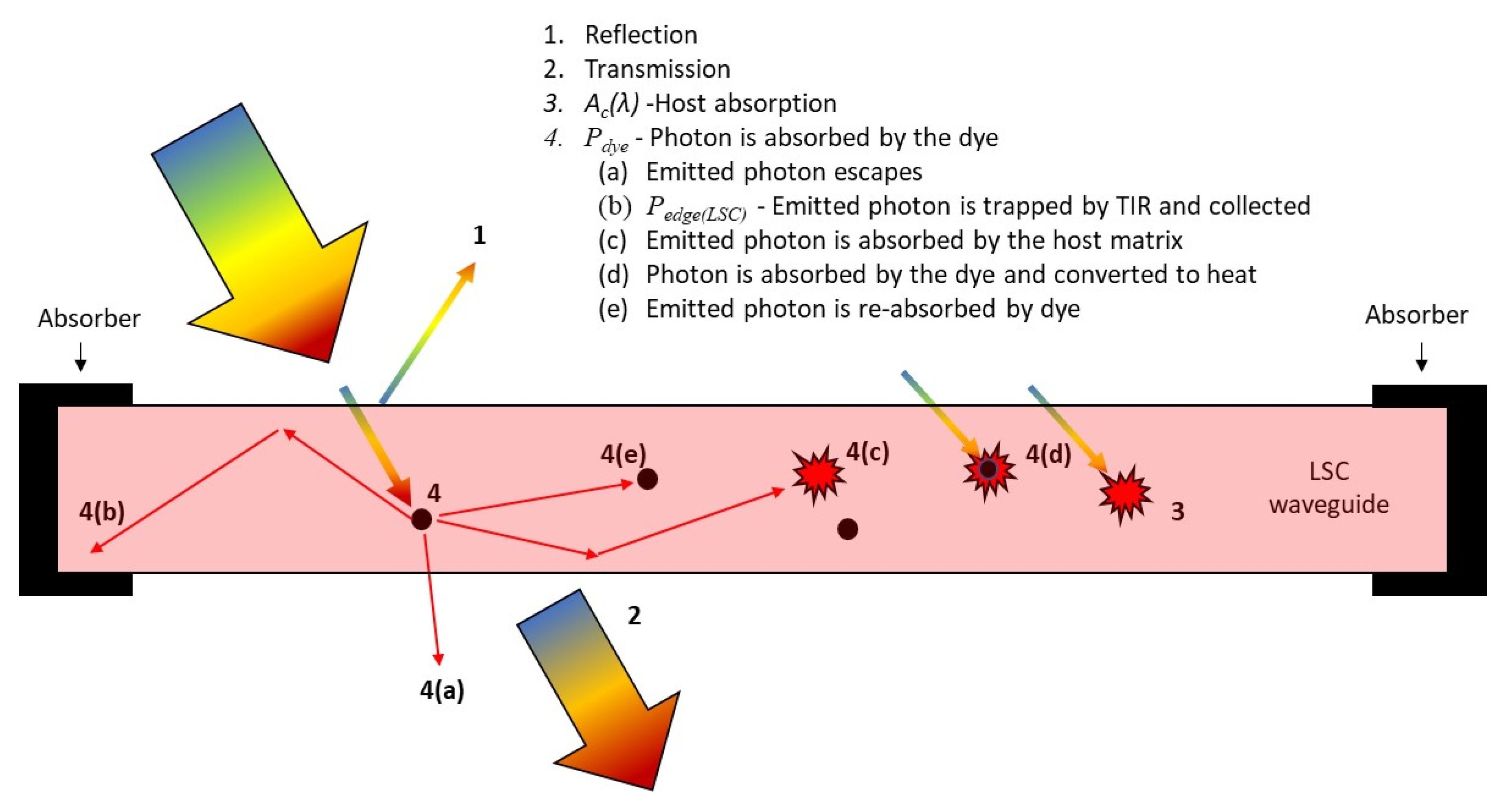
LSCs are composed of a transparent sheet, which acts as a waveguide, impregnated with luminescent dye molecules such as organic dyes. A portion of the photons entering the waveguide are absorbed by the dye molecules which subsequently emit another photon, at a slightly lower energy, in a random direction. The emitted photon has a high probability of being trapped in the waveguide due to total internal reflection, causing the photon to be reflected at the surfaces of the waveguide as it propagates towards the edges of the sheet, where it can be harvested [
8,
9,
10]. LSCs have been investigated extensively for electric power generation by using photovoltaic cells to harvest photons impinging on their sidewalls. For example, G. Liu et al. [
11] reported a solar to electric conversion efficiency of 2.85% for a large 100 cm × 100 cm LSC, N. Aste et al. [
12] reported an efficiency of 1.26% for a 50 × 50 cm LSC, and N. Slooff et al. [
13] achieved an efficiency of 7.1% using a small 5 cm × 5 cm LSC. Notably, in addition to electric power, heat is also generated at the LSC sidewalls, which can degrade PV cells or lower their efficiency [
14,
15,
16].
Thermal energy generated at the sidewalls of LSCs can also be used as a heat source [
8]. W. Stahl et al. have shown that temperatures of 550 °C can be achieved in a 3-mm-thick absorber pipe under vacuum when attached to an LSC with an area of 0.8 m
2 that is subjected to a total irradiation of 850 W/m
2 [
17]. In the same study, temperatures higher than 250 °C were reached under diffuse light conditions at an intensity of 150 W/m
2. Moreover, in a theoretical comparison between LSC thermal collectors and conventional flat plate collectors, A. Goetzberger showed that fluorescent collectors have lower thermal efficiencies at low temperatures but retain higher efficiencies at high operating temperatures [
18]. Despite these promising results, very little research has been done to investigate the thermal applications of LSCs.
The objective of this paper is to measure the thermal energy output from LSCs under practical conditions for building applications. These conditions include normal temperatures and pressures and an absorber at the LSC edges that is comparable to the size of a typical window frame. The experimental results are attained using Newton’s law of cooling. Moreover, the amount of thermal energy generated is used to evaluate the potential of harnessing thermal energy from LSCs to make a meaningful contribution towards alleviating energy demands in an urban environment.
3. Materials and Methods
Optical Characterization of Luminescent Solar Concentrators: Four fluorescent acrylic sheets, coloured green, yellow, orange, and red, were acquired from Plastic World. Additionally, a clear acrylic sheet, to be used as a reference, was acquired from the same source. The transmission and reflection of each sheet was measured and recorded using a UV-Vis Spectrometer (Shimadzu UV-2600 spectrophotometer) at each wavelength from 300 to 1000 nm at 1-nm increments. The spectral transmittance, diffuse transmittance, and diffuse reflectance were measured. The diffuse spectra were measured using an integrating sphere, and the incident angle for the diffuse reflectance spectra measurements was 4°. For each acrylic sheet, the absorption was calculated using the transmittance and reflectance spectra as described with reference to
Figure S1 in the Supplementary Information Section. The general equation for determining absorption is given as Equation (1).
where
T is the total transmission and
R is the total reflection. Noting that both the fluorescent dye and the acrylic matrix within the sheets contribute to the absorbance spectra, the absorbance for the clear sheet,
Ac(
λ), was subtracted from the absorbance for each fluorescent sheet,
Af(
λ), to determine the amount of light captured by the dye,
Adye(
λ), as shown in Equation (2).
The amount of light energy absorbed by the dye within each fluorescent sheet was determined as the summation of the incident light intensity at each wavelength,
I(
λ), multiplied by the dye absorbance spectrum,
Adye(
λ). As shown in Equation (3), this summation is taken over the spectral region from
λ = 300 to 1000 nm to find the radiant power captured by the dye,
Pdye.
Luminescent Solar Concentrator Module Fabrication: To measure the thermal power generated at the edges of the LSCs (Pedge(LSC)) a black absorbing frame was built around a square 0.5 m × 0.5 m acrylic sheet for each colour of florescent LSC to be tested. A similar black frame was also built around the clear acrylic panel to measure the thermal energy generated at the edge of the clear acrylic sheets (Pedge(host)). The framed acrylic sheets, referred to herein as modules, were then placed under a light of known spectral irradiance, and the temperature at the frame was measured. After the panel reached steady state, the light source was removed, and the panel was allowed to cool. Newton’s law of cooling was used to calculate the thermal power provided at each absorber frame when the modules were subjected to illumination.
The absorbing frames used to make the LSC modules were made from three pieces of aluminum sheet metal sandwiched together as shown in
Figure 2a. The outer aluminum sheets were 1.5 mm thick and the inner piece was 3 mm thick, which is the same thickness as the acrylic sheets. Both the inner and outer aluminum sheets were 25 mm wide. The three pieces were glued (using gorilla glue) and clamped together with a 5-mm offset, creating a channel that is the same width as the panels. The inside of the channel was painted with flat black spray paint.
The channel was then filled with clear epoxy and the edge of the acrylic sheet was inserted into the channel and clamped until the epoxy set. This created an optically transparent bond between the absorber and the acrylic sheet that allowed photons incident onto the edge of the acrylic sheet to impinge upon and be absorbed by the aluminum frame. It is desirable for the epoxy to have a similar index of refraction to that of the acrylic (1.5) to prevent internal reflection at the boundary. The index of refraction for epoxy is generally between 1.45 and 1.57, which is well-matched with the index of refraction of the acrylic to provide for minimal reflection. In this study, Art Resin two-part clear epoxy was used for its optical clarity, non-yellowing protection, and UV resistance. The resulting module has an aluminum absorber surrounding each edge as shown in
Figure 2b. In this work, it was assumed that all light incident onto the edge of the fluorescent acrylic sheets contributed to the thermal energy generated at the frame of the modules.
Experimental Set-up: To measure the thermal energy generated at the edges of the fluorescent LSC modules, they were placed under two 1000-W Sunmaster FullNova MH light bulbs (41983 SM. 1000 W.FullNova), which were operated at full power under a white reflector. The frames were supported at their corners such that the LSC modules resided 5 cm above a table to prevent conductive heat losses from their underside. The temperature of the frame was measured using K-type thermocouples, which were secured to the underside of the frame using aluminum tape ¼, ½, and ¾ of the way along the length of one of its edges, as shown in
Figure 3. A 1 mm thin aluminum reflective shield was placed 5 cm above the absorbing frame to prevent it from receiving light directly from the lamps. The modules were left under the lamps for approximately 2 h, allowing them to reach steady state. Subsequently, the lamps were turned off and the modules were left to cool to room temperature. The temperature at the three positions indicated in
Figure 3a were measured and recorded every 5 s over the duration of the experiments. A fan (6-inch VIVOSUN 390 CFM inline Duct Fan) was used to provide forced convection cooling across the modules to maintain a constant heat loss condition. An aluminum surface placed on the table beneath the module was painted black to minimize the reflection of light that passed through the modules. The size of each module is 50 × 50 cm, for a total area of 0.25 m
2. Each LSC module and the clear acrylic module were tested three times.
Solar simulated radiation was generated using two 1000-W Sunmaster FullNova MH lamps (41983 SM. 1000 W.FullNova). The light spectra of the lamps from 360 to 1000 nm, which accounts for 50% of the radiant energy from the lamps, was provided by the manufacturer and is shown as
Figure S2 in the Supplementary Information Section. The lamps were placed 60 cm above the modules. To determine the amount of radiant power incident onto the module surface, 16 measurements were taken using a ThorLabs PM16-401 power meter in a grid pattern over the area of the panel. The lamp intensity distribution and the position of the thermocouples are shown in
Figure 3b. The average light intensity incident onto the LSC modules during the experiments is 47.9 mW/cm
2, and the average lamp intensity between 360 and 1000 nm was 23.95 mW/cm
2. The lamp spectra and the total measured irradiance were used to find the light energy at each wavelength that was incident during the experiments.
Numerical Methods: Newton’s law of cooling states that the temperature difference between a cooling body and its surroundings decreases exponentially with time. Newton’s law of cooling is applicable when the temperature difference between the object and its surroundings is small compared to the temperature of the object and when heat loss is dominated by forced convection [
19,
20]. The temperature of an object that obeys Newton’s law is given by Equation (4).
where
T(
t) is the temperature at time
t,
Ta is the ambient temperature, and
T0 is the initial temperature of the object under consideration. Furthermore,
k represents the cooling constant, which is proportional to the area,
A, and convective heat transfer coefficient,
h, of the object, and inversely proportional to the objects heat capacity,
Cp. As per Newton’s law of cooling, the cooling rate will remain constant if all geometric and heat transfer properties remain the same, as is the case for the experiments performed in this work.
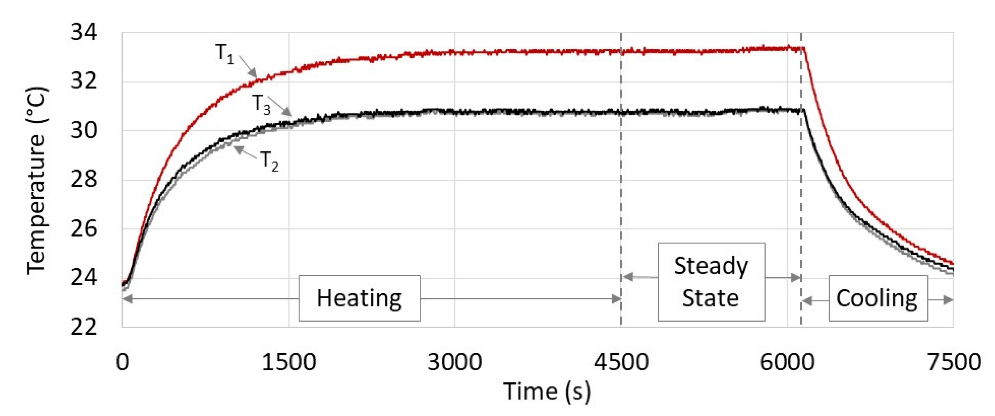
Herein, we measure the cooling rate of the aluminum frame after the lamps were turned off, using the thermocouples indicated in
Figure 3 to determine their cooling constants. For example, the temperature profiles recorded during one of the tests for the red LSCs are shown in
Figure 4. It was assumed that steady state had been reached when the variation in the temperature readings from the thermocouples differed by less than ±0.2 °C from the average reading over a duration of at least 25 min. In addition, the data range used to determine the cooling coefficient had a duration of at least 250 s, and the coefficient of determination for fitting the cooling curves was 0.958 or greater for all tests (for more than 85% of the tests the coefficient of determination was greater than 0.97). As described subsequently, once the cooling constant for the aluminum frame,
kf, has been determined the heating power provided by the modules (
Pedge(LSC) or
Pedge(host)) can be calculated using the temperature measurements of the aluminum frame attained during steady-state illumination conditions.
Given the cooling constant for the absorber frame,
kf, its rate of temperature change can be calculated using Equation (5):
where
Tf is the temperature of the aluminum frame. Furthermore, the heat transferred from the frame to the ambient,
Qout, during the cooling experiments can be related to the rate of temperature change of the frame according to Equation (6):
where
Mf and
Cpf are the mass and heat capacity of the aluminum frame, respectively. Combining Equations (5) and (6) leads to an expression for
Qout in terms of the cooling constant and the temperature of the frame, as shown in Equation (7):
Furthermore, at steady-state illumination conditions
Qin = −
Qout, where
Qin is the energy from the lamp that is ultimately transferred to the aluminum frame. That is, under steady-state illumination conditions,
Qin is equal to the thermal power provided by the frame of the LSC module,
Pedge(LSC) (or
Pedge(host) for the clear module) and is given by Equation (8).
where
Tf-steady-state is the temperature of the aluminum frame measured under steady-state illumination conditions. Once the heating power has been calculated for each module, the module heating power from the reference (clear) panel,
Pedge(host), was subtracted from that of the LSC modules,
Pedge(LSC) to determine the power contribution from the dye,
Pdye-Optical.
4. Results
The dye absorption spectra and power absorbed by the dyes within the 0.25 m
2 LSC modules are shown in
Figure 5a,b, respectively. The total amount of power absorbed by the dyes under solar-simulated radiation ranges from 11.6 W for the green LSC to 19.6 W for the orange LSC. The total thermal power generated in the aluminum frames, measured using Newton’s law of cooling, is plotted in
Figure 5c. The power transferred for measurements performed using thermocouples at positions one, two, and three are shown in
Figure 5c for each panel as the bars on the left, middle, and right, respectively. The value plotted is the amount of power that would be absorbed by all four sides of the frame, if the heat transferred at the position of thermocouple represented an average value. For all panels, the amount of thermal energy transferred is the largest at position one. For the clear panel, the aluminum frame generates 10.2, 9.6, and 7.2 W of thermal energy at positions one, two, and three, respectively. The clear panel generates heat during the experiment because it absorbs incident light in the UV and NIR spectral regions. Notably, 50% of the radiant energy from the lamp is outside the spectral region from 360 to 1000 nm (in comparison 28% of the AM1.5 solar spectrum resides outside this spectral region) and the clear acrylic panels will absorb relatively more NIR radiation under the solar-simulated light as compared to what would be absorbed under sunlight.
The heat generated in the frame for the clear panel is used as a reference to determine the amount of thermal power transferred by the dye to the aluminum frame within each LSC panel. That is, the luminescent power from the dyes in each LSC that is converted to thermal energy at the aluminum frame is determined by subtracting the results for the clear panel from the results for the LSCs at each thermocouple position, and the results are plotted in
Figure 5d. The greatest amount of heat transferred by the dyes occurs for the red LSC, while the least amount of heat transferred occurs for the orange LSC. The orange LSC shows poor luminescent heat transfer, even though the dye in the orange LSC absorbs more power than the dyes in the other LSCs. This is likely due to a low quantum yield for the dyes within the orange LSC.
For all LSC panels, the luminescent power transferred by the dye is less than half the total thermal power generated in the frame during the experiments for the clear panel. Here it can be noted that the dye is converting a relatively narrow band of the incident radiation spectra; the width of the absorption spectra for the LSC panels is about 200 nm or less. In this regard, the amount of thermal energy can be increased by stacking LSC panels together to absorb incident light over a broader spectral range. For example, we fabricated a triple-panel LSC module comprised of a yellow LSC sandwiched between red and blue LSCs, which generated 20.0 W over its 0.25 m2 surface area using the same experimental conditions as those used for the single-panel modules. Furthermore, considering the amount of energy available from the solar irradiance, there is a large capacity and potential to increase the amount of thermal energy generated in the LSC frames. Strategies for increasing the heat generated at the sidewalls of the LSC modules are discussed in the following section.
5. Discussion
On a per square meter basis, the dyes within the red LSC modules generated the largest amount of thermal energy. The average thermal power generated at the aluminum frame for the red LSC module was 4.48 W. As shown in the
Supplementary Information Section, assuming a mean daily insolation of 5 kWh/m
2 (or mean daily insolation of 3 kWh/m
2 for a vertical surface) the dye in the red LSC would produce ~100 kWh/m
2 (or ~60 kWh/m
2 for the vertical surface) annually. These values are comparable to the annual energy consumption in a typical building which ranges from 100 to 600 kWh per square meter of floor space [
3,
4]. Thus, if the surface area of a building is comparable to its floor space, thermal energy generated from LSCs on the building’s surface could be used to reduce the buildings energy density.
Semi-transparent LSC modules that generate heat can provide niche benefits for applications in the built environment. For example, blue LSCs, which transmit most of the visible spectrum, may be used as window coverings that harness a portion of the solar irradiance while still providing adequate indoor lighting. Furthermore, ytterbium chelates, cyanine-like dyes, and near-infrared fluorescent dyes containing a tricoordinate boron atom could be used to harvest the near-infrared portion of the solar irradiance in LSC window coverings that generate heat at their sidewalls [
21,
22,
23]. Notably, in warmer climates, the LSCs may provide the double benefit of reducing the cooling load of the building by preventing solar energy from entering and by providing thermal energy at its sidewalls which could be stored or used for water heating. As another example, LSC modules that absorb green light, which is not required for photosynthesis in many crops, can be used as greenhouse rooftops [
24]. Thermal energy generated at the sidewalls of these modules may be stored, or rejected to the surroundings, to control the greenhouse temperature without venting, which may cause unfavorable CO
2 concentrations or humidity levels.
There is potential to increase the amount of thermal energy generated at the sidewalls of LSC modules compared to the results reported in this work. For example, re-absorption losses can be reduced by modifying the host matrix to increase Stokes shift [
25], and emission losses can be reduced by using a host matrix with a higher index of refraction [
26] or by orienting the dye molecules within the LSC [
27]. Emission losses can also be reduced by using dielectric mirrors at the surface of the LSC modules [
28]. Moreover, diffractive structures such as gratings and photonic crystals located at the surface of LSC modules can enhance the propagation of incident solar photons to the LSC sidewalls [
29,
30,
31,
32]. The shape and size of the LSC also affect its efficiency [
33]; generally, the efficiency of LSCs increases with decreasing size, however, the edge-length of the LSCs also increases with decreasing size which may make it more difficult to collect thermal energy generated at the LSC sidewalls.


