Abstract
The design of rolling stock plays a key role in the attractiveness of the rail transport. Train design must strictly meet the requirements of rail operators to ensure high quality and cost-effective services. Semiconductor power devices made from silicon carbide (SiC) have reached a level of technology enabling their widespread use in traction power converters. SiC transistors offering energy savings, quieter operation, improved reliability and reduced maintenance costs have become the choice for the next-generation railway power converters and are quickly replacing the IGBT technology which has been used for decades. The paper describes the design and development of a novel SiC-based DC power electronic traction transformer (PETT) intended for electric multiple units (EMUs) operated in 3 kV DC rail traction. The details related to the 0.5 MVA peak power medium voltage prototype, including the electrical design of the main building blocks are presented in the first part of the paper. The second part deals with the implementation of the developed SiC-based DC PETT into a regional train operating on a 3 kV DC traction system. The experimental results obtained during the testing are presented to demonstrate the performance of the developed 3 kV DC PETT prototype.
1. Introduction
Rail is among the most efficient and lowest emission modes of transport. It is under constant pressure to increase the accessibility of connections and quality of passenger services to enhance their competitiveness with other transport modes. For rail to compete more effectively with other modes of transport and attract more passengers, it needs the next generation of passenger trains that will be lighter, more energy-efficient and cost-effective. Traditional passenger trains consisting of a locomotive and several carriages penalize performance in terms of acceleration since they have a limited number of available drive wheelsets. Modern electric multiple units (EMUs) do not require a locomotive, as they consist of several self-propelled units in a fixed assembly. Traction is distributed along the length of the train and the motors are housed by bogies of different carriages [1]. The demand for EMUs used for local, regional and intercity transport, grows globally every year. Thanks to the use of common bogies for the central wagons, EMUs are shorter and lighter than trains pulled by locomotives. This translates into lower movement resistance, better acceleration and lower energy consumption [2]. Moreover, EMUs better implement the specificity of passenger traffic and station service as they have a greater number of doors and provide better exchange of travelers.
Quantitatively, the most important part of energy drawn from the overhead traction line by an EMU is consumed by the traction propulsion systems. Traction drive is crucial for the EMU’s efficiency, reliability and availability. The on-board propulsion converters, which for years have been traditionally installed in separate technical compartments, are currently mounted on the roof [3] or under the floor [4,5] of the EMU train. This corresponds to the growing requirements for the number of passenger seats due to the limited length of the passenger train.
The most common R&D works carried out by the manufacturers of traction drives are focused on improving efficiency and reducing the size of the on-board propulsion and power systems [3,4,5,6]. Another important topic is the reduction of noise emission [3]. Noise from mechanical and electrical components is troublesome to the human ear and significantly reduces travel comfort. A noticeable source is the working traction motor, whose noise depends on the frequency of switching transistors and the control method used in the drive inverter [7,8].
In the case of a drive inverter for rolling stock for 3 kV DC traction, it would be difficult to find any significant changes in the construction and control technology in the last decades [2,9,10]. The 3 kV dc-line voltage is a challenging task for power electronics. Due to a significant voltage drop on the overhead line, the traction power supply works at a higher voltage, usually 3.6 kV or even higher. This results in a requirement where the operation of a vehicle is often expected from 2.4 kV up to more than 4 kV, with the nominal power available from 2.8 kV or 3 kV DC [9]. A power conversion chain operating under direct current catenary is reduced to a bulky input filter and a voltage source inverter (VSI). Nowadays, EMUs powered by 3 kV DC voltage are equipped with two-level VSIs constructed of six 6.5 kV insulated gate bipolar transistors (IGBTs) generating pulse width modulated (PWM) voltage for supplying medium voltage asynchronous traction motors.
A small number of EMUs are equipped with three-level neutral point clamped (NPC) VSIs using 3.3 kV IGBTs [11]. A typical traction drive with a two-level VSI is shown in Figure 1a. In such a system, the LC filter capacitor also takes on the role of energy storage and is cyclically charged and discharged with impulse currents. The line filter choke, which is the most massive element of the inverter and weighs several hundred kgs, serves to limit high frequency, high di/dt pulse currents flowing between the catenary and the traction vehicle when the capacitor is recharged.
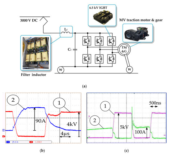
Figure 1.
Conventional electric drive of 3 kV DC traction rolling stock with asynchronous traction motor and 6.5 kV IGBT-based two-level inverter: Lf, Cf—inductance and capacitance of the traction line filter; TM&G—traction motor and gear, w—wheels (a); Typical collector-emitter voltage (1) and collector current (2) transients during switching of the 6.5 kV IGBT, 4μs/div (b); Typical drain-source voltage (1) and drain current (2) transients during switching of the 10 kV SiC MOSFET, 500 ns/div (c) (comparison in the text).
The power supply of the inverter has a large impact on both noise and the electromagnetic and thermal properties of traction motors. Table 1 shows the switching frequencies of HV IGBTs used in propulsion inverters for 3kV DC traction.

Table 1.
Switching frequencies of HV IGBTs used in rail inverters for 3kV DC traction.
The harmonic voltages caused by PWM inverters operated with frequency ranging from individual hundreds of Hz to 2 kHz are the cause of significant current heat losses in the traction motor winding resistances [7,8]. The additional losses due to inverter supply can amount in the range of a few percent of the rated motor power and also occur in the laminated core of the traction motor. The winding and core losses most notably entail thermal problems, increasing the traction motor temperature by an average 30–50 K compared with a sinusoidal supply [8], but also lead to reductions in efficiency. Moreover, the negative effects of the low frequency PWM operation of the inverter feeding the traction motor are increased mechanical loads and increased noise emission. Typical voltage and current transients during the switching of the 6.5 kV IGBT are shown in Figure 1b. The main reason for low IGBT switching frequency are the relatively long switching times of the order of several microseconds and a characteristic current tail during turning off. The increase in the switching frequency of IGBTs would be at the expense of an unacceptable increase in the switching losses. Due to the above-mentioned reasons, current research and development conducted by manufacturers of the traction drives for rolling stock are focused on the utilization of new generation power transistors made of silicon carbide (SiC). Thanks to the exceptional properties, such as: significant achievable energy savings, quieter operation, improved reliability, and reduction in maintenance costs, SiC MOSFETs are ideal for traction power converters new designs instead IGBTs—which were in use in the rolling stock industry for decades [3,4,5,6,10]. The most obvious benefit of SiC metal-oxide semiconductor field-effect transistors (MOSFETs) compared to IGBTs is a significant reduction in switching losses, up to 55%, and total power losses, up to 80% [6].
Typical voltage and current transients during switching of the 10 kV SiC MOSFET are shown in Figure 1b. As it can be seen from Figure 1, in the case of an SiC-MOSFET there is in principle no tail current, and so without this contribution, clearly the switching loss is extremely smaller. Table 2 shows the overall losses distribution between the switching and conductive losses for HV SiC MOSFET and HV IGBT technology [12].
Table 2.
Loss comparison between IGBT and SiC MOSFET: 5 kV, 33A/cm2, 50% duty [12].
The IGBT switching frequency is limited by the power dissipation, which increases the IGBT junction temperature. To preserve the reliability of operation, the total power dissipation density is limited at the value of 200 W/cm2 which maintains the chip temperature of 125 °C. The packaging technology further reduces the switching losses of the IGBT to 100 W/cm2, which is the reason for limiting the operating frequency of the 6.5 kV IGBT-based two-level inverters to below 1000 Hz.
Lower switching losses of HV SiC MOSFETs give the possibility of increasing the PWM frequency of the propulsion converters towards tens of kilohertz. This, in turn, makes it possible to reduce the size of passive components of the traction inverter-primarily the bulky traction line filter. The weight of the filter inductor for the conventional traction inverter shown in Figure 1a is about 500 kg. The unique properties of SiC transistors allow to reduce the weight of the input filter inductor proportionally to the increase in the switching frequency. The issue supporting the reduction of dimensions of the input filter is the use of an additional high-efficiency active-front end (AFE) stage at the input of the traction inverter, which provides regulation of the current drawn from the grid. Due to the lower losses of SiC devices, the need for cooling is also substantially reduced [5]. Reducing the size of the cooling system leads to a reduction in the volume, weight and costs of the entire traction drive [6,8,9,10].
The higher resolution of the PWM generation in SiC-based traction inverters has a positive effect on reducing harmonic losses of the traction motors-making the whole traction systems more efficient. As stated in [4], the use of SiC power modules combined with expanding the control region outputting regeneration torque have made it possible to reduce the energy consumption rate of the railbound vehicle operated on suburban line by more than 37% compared to conventional systems. By increasing the PWM frequency above 20 kHz the acoustic noise level on the platform and in the cabin may be pushed beyond the audible range. In the case of railway inverters, the switching frequency of high voltage (3.3 kV and 10 kV) MOSFET SiC transistors is several kHz [4,5,6]. In order to obtain noiseless operation of MV drives, multi-level topologies are used with the use of low-voltage (1.2 kV or 1.7 kV) SiC transistors. Among others, power electronic traction transformers (PETTs), built with power electronic building blocks (PEBB) with built-in input/output isolation, realized by small size and high power density medium frequency transformers (MFT) are of particular interest [13,14,15,16,17,18,19].
So far, the primary purpose of SiC-based PETTs were primarily traction drives powered from the AC lines: 15 kV/16.7 Hz [13,14,18,19] and 25 kV/50 Hz [15,16,17]. AC powered locomotives and EMUs have a complex and voluminous conversion chain including a step-down transformer, rectifier, low-frequency filter and traction inverter. Conventional line frequency transformers (LFTs) used in AC EMUs occupy up to 12% of the weight of rail vehicle and a corresponding part of the train space [2]. Lightweight PETTs using MFTs, if they replaced bulky LFTs, could be easily installed on the roof, resulting in more space for passengers inside the train. AC PETTs offer not only a way to reduce the weight of the on-board electric equipment, but also to add additional functionalities and improve energy efficiency [19].
Strictly speaking, the AC PETT replaces the system of an LFT and an active rectifier and the AC PETT topology does not include a propulsion inverter, which stays the same as in a classical propulsion system and is connected to DC output terminals of the PETT [3,13,14,15,16,17,18,19].
As it has been highlighted in [13], the presently most promising medium frequency MF topologies for traction feature on their input-side a large number of series connected four-quadrant converters, with an overall switching frequency in the range of 5–8 kHz, modulated with Phase-Shifted PWM. The results presented in [13] have shown that the use of a passively-damped LCL filter for the input-side results in a significantly lighter solution, compared to a single-pole type (single inductor) reported in most cases. The work [14] shows the benefits of using the originally 15 kV/16.7 Hz-type PETT in a traction drive supplied from a 3kV DC network. The main innovation aspect of the PETT proposed in [14] is the possibility to be operated with a HV-AC electric system, as well as after reconfiguration on a MV-DC catenary. A three-stage technology have been studied. Four-quadrant converters (4QC) connected in cascade and forming the PETT input stage provide, via insulated dual active bridge (DAB) DC-DC converters, voltage stabilization at the output DC terminals of the PETT, while limiting the ripple of current drawn from the DC traction network. Two solutions have been presented: the first solution using hard switching techniques, using a three-times silicon-conversion, and a second solution based on ZVT/ZCS switching of silicon semiconductor devices. The DC PETT described in [14] provides a higher quality of drive operation during DC voltage disturbances which normally occur in 3 kV DC traction, than conventional propulsion systems with two-level and three-level inverters. Prototype modules have been realized with association of diodes and IGBTs in order to provide reverse-blocking devices. However, the concept was verified only on a small scale test rig. The works [15] and [16] present the method of optimal sizing of 25 kV/50 Hz-type PETTs using 3.3 kV SiC MOSFETs that leads to the best efficiency at rated power in a given volume. The authors emphasize that the efficiency cannot be the only parameter to make a clear choice of an isolated DC-DC converter included in a PETT. An important parameter should be also the acoustic noise, even if it is difficult to take it into account in preliminary studies. The results obtained in [16] for 3.3 kV SiC MOSFET-based resonant DC-DC converters show that designing converters with a switching frequency in the range of 20 kHz would not lead to a dramatic reduction of the PETT efficiency. In [19] the design and development of the 1.2 MVA medium voltage PETT prototype for 15 kV/16.7 Hz traction applications have been presented. The use of MFTs developed in [19] allows for weight reduction and power density improvement (0.5–0.75 kVA/kg) compared to conventional traction chains (0.2–0.35 kVA/kg). The authors highlight the new possibilities in terms of management of the railway networks due improved power quality and grid compliance due to the multilevel input voltage waveform and high apparent switching frequency seen from the grid side. The application of PETT to 3 kV DC rail traction means that the entire modular converter operates at much lower maximum voltage than in the case of the AC PETT, which encourages the integration of the propulsion inverter within the structure of the DC PETT with the use of unified low-voltage cells. The use of low-voltage (1.2 kV or 1.7 kV) SiC devices for this purpose seems to be an excellent solution.
The presence of built-in galvanic isolation in low voltage cells, realized utilizing MFTs, allows for series connection of the cells on the catenary side to obtain DC rail traction voltage and, independently, the configuration of the output terminals of the cells as a three-phase medium voltage multi-level inverter on the traction motor side. However, the use of low voltage power devices and electronics in combination with high insulation requirements, imposed by the application to 3 kV DC rail traction, is a challenging research topic regarding the insulation strength of the cells, in particular SiC power devices and MFTs.
The world’s first and only traction unit equipped with the roof-mounted SiC-based 3 kV DC PETT is shown in Figure 2. It is the PESA 308 EN81 series electric passenger railcar (construction number 308B-007) with an originally rated power of 560 kW that operates in Polish regional passenger rail transport since 2007. The work presented in this paper covers some of the recent research and development efforts to develop, design, test, commission, and install of the 335 kVA (500 kVA peak) SiC-based 3kV DC PETT on the PESA 308 test traction unit for a field trial.
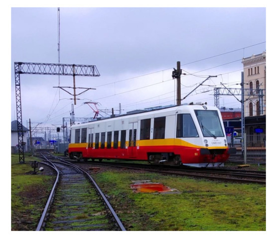
Figure 2.
The EN81 series 3 kV DC electric passenger railcar used for the field trial with the roof-mounted SiC-based DC power electronic traction transformer (PETT) prototype.
2. Configuration of the 3 kV DC PETT Topology
The general description of the 3kV DC traction propulsion system with the SiC-based DC PETT is shown in Figure 3.
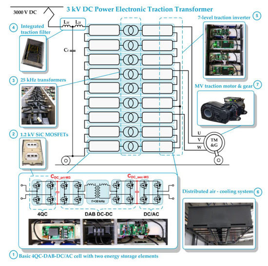
Figure 3.
General scheme of the SiC-based 3 kV DC PETT: (1) Basic 4QC-DAB-DC/AC power electronic cell with two energy storage elements; (2) 1.2 kV SiC MOSFET power modules assembled in a 9 kV insulation frame; (3) medium frequency transformers; (4) compact input LCL traction filter; (5) output stage configured in the form of seven-level CHB inverter; (6) medium voltage traction motor integrated with the gear; (7) distributed air cooling system; U, V, W—traction motor phases.
The key parts of the system include: nine power electronic cells (1) each consisting of eight commercially available 1.2 kV SiC MOSFET power modules (2) and medium frequency transformers (3) placed in separate air-cooled chambers; a compact input traction LCL filter of a small size has an area of a small chamber (4); a medium voltage asynchronous traction motor integrated with the gear unit (7). The DC PETT has, essentially, a three-stage construction: (1) DC input conversion stage; (2) AC output conversion stage and (3) AC-link, which is an especially designed medium frequency power transformer. The DC input conversion stage is used to adapt constant frequency DC traction voltage to a medium frequency required for conversion, while the AC output stage adapts medium frequency of the AC link to the output AC voltage useful for controlling the traction motor. The input terminals of the nine power electronic cells are connected in series which means that the DC PETT input stage is configured as a 19-level cascaded H-bridge four-quadrant converter (4QC) supporting the 3 kV DC railway traction network. The output terminals are connected in series, three pairs of terminals per phase, creating a three-phase output stage, which means that the traction motor is supplied by a three-phase seven-level cascaded H-bridge (CHB) traction inverter. Table 3 lists the overall system requirements and specifications.
Table 3.
3kV DC PETT system specification.
The proposed SiC-based DC PETT takes full advantage of the SiC technology while meeting the requirements of train manufacturers. During DC PETT operation, the energy drawn from the 3kV overhead contact line is processed in discrete portions, with full DC voltage divided into 19 levels, which helps meet stringent electromagnetic compatibility (EMC) standards, including EN 50121-2, EN 50121-3-1, EN 50121-3-2 and EN 50238. The use of a cascade system of series-connected 1.2kV SiC MOSFETs to switch the full voltage of the railway traction enables a much higher operating frequency of the power converter than using HV counterparts. At the same time, the selection of low-voltage transistors with high switching frequency can provide noiseless operation with comparable or even smaller total switching losses of the power converter [19]. The internal terminals of the power electronic cells are configured as nine DAB DC-DC converters connected in series and forming the insulation stage of the DC PETT. Each of the nine 4QC-DAB-DC/AC power electronic cells assembled in this configuration is rated for 38 kVA (56 kVA peak). Each cell, in addition to the galvanic isolation realized with the MFT, contains two energy storage elements, which is a characteristic feature of PET devices and enables the independent implementation of various control tasks at the input and output of the device.
As the heat generation is concentrated around the MFTs and SiC power modules, a distributed air cooling system (6), when uses PWM controlled fans and eighteen cooling ducts is provided in order to deal with the heat. The use of low voltage SiC MOSFETs makes the construction of the DC PETT more competitive in price than two-level traction inverters using HV SiC MOSFETS due to very high costs of high voltage semiconductor power devices, high voltage capacitors and other high voltage electronic components. The price of CAS120M12BM2-type 1.2 kV/193 A SiC MOSFET power module starts at about $300, the price of CAB450M12XM3-type 1.2 kV/450 A SiC MOSFET starts at about $700, while for the 3.3 kV nHPD2-type SiC MOSFET modules prices start at about $9500. The 10 kV and 6.5 kV SiC MOSFET power modules are not available on the market yet.
The modular construction of the DC PETT ensures even weight distribution on the roof of the EMU train. The center of gravity of the device is distributed symmetrically on both sides of the longitudinal axis of the vehicle. The distribution of the basic cells of the PETT on the EMU roof surface is shown in Figure 4. The operation of current-controlled nine-level four-quadrant converter connected to the 3 kV DC traction enables the minimization of the integrated input LCL traction filter and the mitigation of the resonances coming from the railway grid at a level that cannot be obtained in a conventional two-level inverter. As it can be seen from Table 3, for the investigated EN81 railcar, the weight of the traction filter chokes was reduced by nearly 10 times.
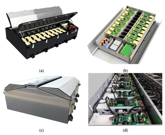
Figure 4.
Assembly of power electronic cells of the DC PETT on the roof surface: (a) overall view of the whole device from the CAD program; detailed view of the 4QC-DAB-DC/AC power electronic cells and the LCL filter in the middle at the bottom (b); photos of the prototype (c) and (d).
Moreover, modular construction enables quick replacement of individual cells in case of failure. Therefore, the minimization of the MTTR (Mean Time to Repair), which is one of the basic indicators of reliability required in the railway industry [20,21] can be provided.
3. Low Voltage SiC Power Modules
According to numerous recent publications, e.g., [20,21], cascaded cells converter systems, such as the CHB topology, are a very attractive solution to interface power electronic systems to MVA-scale medium voltage applications. For the systems connected to medium voltage grids the choice of fast switching and low voltage drop 1.2 kV or 1.7 kV devices (giving up to 15 cells per phase stack) can be the most suitable trade-off between efficiency and power density, with efficiencies above 99% at a power density of about 5 kW/dm3 [22].
Higher switching frequency obtainable at lower blocking voltages allows to reduce loss and volume contributions of the grid filter inductances and the cooling system.
With the wide availability of low voltage SiC MOSFET power modules on the market their performance in the range of maximum working currents offered is constantly increasing along with the progressive heat dissipation capacity. Figure 5 shows a comparison of the dimensions of the 1.2 kV SiC MOSFET power module, part no. CAS120M12BM2, used in this project, with a rated drain current of 138 A (TC = 90 °C), RDS(on) = 23 mΩ, junction to case thermal resistance RthJC = 0.125 °C/W, maximum dissipated power PD = 450 W (TC = 90 °C) characterizing commutation circuit series inductance of 15nH and a base surface of 65.4 cm2, and new generation 1.2 kV SiC MOSFET power module, part no. CAB450M12XM3, available on the market from mid-2019, with 3 times higher rated drain current ID = 409 A (TC = 90 °C), RDS(on) = 4.6 mΩ, RthJC = 0.11 °C/W, PD = 750 W (TC = 90 °C), and characterizing commutation circuit series inductance more than twice as low, Lstray = 6.7 nH and 36% less footprint.
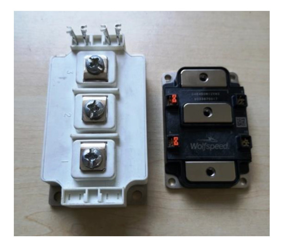
Figure 5.
The 1.2 kV SiC MOSFET power module, part no. CAS120M12BM2, used in the project, with a rated current of 138 A (left) and a 36% smaller 1.2 kV SiC MOSFET power module, part no. CAB450M12XM3, with a rated current of 409A, available on the market from mid-2019.
The use of SiC MOSFET 1.2 kV power modules in the design of the proposed 3 kV DC PETT requires higher insulation strength than the original housing offers to withstand the full operating voltage of the converter. To increase the voltage strength, an additional frame made of insulating material has been developed and mounted between each transistor module and the heat sink, which is shown in Figure 6. A flexible, thermally conductive silicone film with thermal conductivity of 5 W/mK and a breakdown voltage of 9 kV AC was used between the base of the power modules and the heat sink.
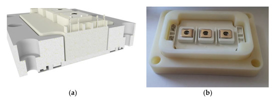
Figure 6.
General view and cross-section of the frame of insulating material, ensuring increased voltage strength of the SiC MOSFET transistor module housing and heat sink insulation: (a) overall view from the CAD program; (b) photo of the prototype.
There are several design challenges associated with switching performance of the SiC power modules which need to be carefully addressed including the minimization of ringing and overshoots caused by the parasitic loop inductance. These loop inductances together with SiC MOSFET output capacitance create a resonant tank, which is the source of unwanted EMI emissions [23,24]. To overcome the ringing, parasitic parameters converter should be minimized by a careful converter design.
Figure 7 shows the drain-source voltage (UDS) of the SiC MOSFET and the primary side transformer current of the developed DAB DC-DC converter measured in the developed SiC-based 3 kV DC PETT during commutation of 700 V DC voltage within 80 ns. A single standard PPA2124150-type, 1.5 uF snubber capacitor was attached to the DC bus of each SiC MOSFET power module. As can be seen in Figure 7, thanks to the obtained minimization of the switching loop inductance the measured magnitude of the voltage ringing is about 40 V (5.7%), which is an acceptable level.
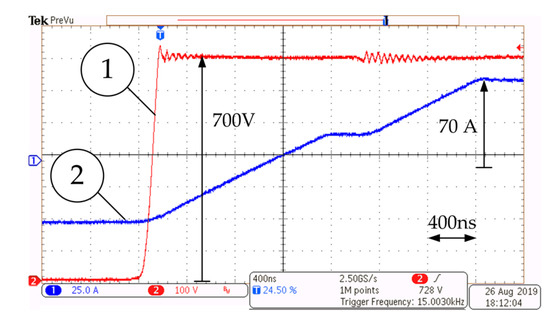
Figure 7.
SiC MOSFET drain-source voltage (1), 100 V/div and the primary MFT current (2), 25 A/div of the developed DAB DC-DC converter during commutation of 700V DC voltage, 400 ns/div.
4. Design of MFT for 3kV DC PETT
The proposed 3kV DC PETT topology requires individual isolated DC-DC converters for the feeding of each H-bridge of the three-phase seven-level traction converter. The primary function is to provide galvanic insulation of each supply voltage [17]. The isolation stage is ensured by nine DAB DC-DC converters [25,26,27,28,29,30,31,32], which, in the same time, are core elements of the entire system (Figure 3). The main idea of the DC-DC DAB converter design is to combine the advantages of hard-switching pulse-width modulation (PWM) topologies characterizing a large dynamic range and no (reactive) circulating power operation and resonant topologies, which can operate in a soft-switching manner with a reduced electromagnetic interference (EMI) and effective utilization of transformer parasitics but, with strongly increased circulating power and a limited dynamic range.
The performance of DAB DC-DC converters and the entire DC PETT system is strongly affected by the design of the MFTs [26]. The key element enabling each DAB DC-DC converter to transfer energy between input DC stage and output AC stage is the series inductance Ls, which acts as a decoupling element between the square-wave voltages and influences the conducted currents and switched currents of all the semiconductors of the active bridges of the DAB DC-DC converter. Series inductance can either be implemented as a separate component, using its own magnetic core, or can be built into the MFT. Using the MFT leakage inductance as the series inductance, Ls = Lσ, simplifies the mechanical design, eliminates the losses and volume resulting from the interconnection of the external inductor, and enables the achievement of higher power densities. However, in some justified cases, the use of additional auxiliary inductance may be unavoidable [33].
The insulation between the primary and secondary side of the MFT must withstand the rated voltage of the DC railway overhead line. Achieving the desired MFT design that will maximize power density and efficiency while maintaining space and weight restrictions requires a complicated optimization procedure [25]. Therefore the following considerations have been taken into account at the design stage:
- Interleaving of windings was not considered in order to avoid voltage isolation problems,
- The windings have been designed to provide very low coupling capacity between primary and secondary side to avoid capacitive coupling currents,
- The coil-formers have been designed in order to implement the required leakage inductance Lσ, at the same time to comply with minimum clearance and creepage distances to the core and to maximize the cooling surface of the windings.
The working principle of the DAB DC-DC converter lies in the phase-shift δ, introduced between the rectangular AC voltages generated by the two active bridges [26,28]. The AC current flowing through the MFT is introduced by the phase shift of the active bridges AC voltages and depends on the difference of the primary and secondary DC voltages Vdc1 and Vdc2 and the value of the series inductance Ls. For rectangular AC voltages characterizing the same duty cycle D = 0.5, the transferred power PDAB is adjusted by controlling the phase angle δ, according to the following formula:
where Ls is the primary-referred leakage inductance [26]. In principle, the designed transformer had to meet the thermal requirements and insulation distances required to achieve the desired leakage inductance. To design and manufacture of two prototype transformers, two types of magnetic material, i.e., amorphous material characterizing high saturation level and N87 ferrite core have been used. Both materials, amorphous and ferrite, are suitable for high power and high-frequency applications and it can be of interest to investigate their performance on two transformer prototypes.
Figure 8 shows the dimensions of the windings and view of the first developed MFT prototype consisting of two high performance iron-based amorphous alloy (Fe-Cu-Nb-Si-B) wound cores with a rectangular shape (core length 222 mm, core width 118 mm, core height 30 mm, core build 35 mm). The classical shell-type structure with two uniform, concentric windings has been selected for the design. The leakage inductance has been set by arranging the position of the primary and secondary windings.
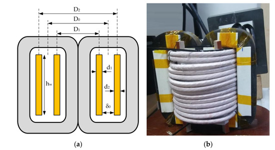
Figure 8.
Main dimensions (a); and the overall view (b) of the first developed MFT with concentric windings of cylindrical shape (auxiliary inductor visible in the right top corner).
Uncut cores have been used, which can help reduce noise emissions from the transformer [27] and are valuable for rail vehicles. Moreover, the absence of an interlayer impregnation, which can be found in cut cores, eliminates additional mechanical stress to the lamination. Both, the primary and secondary windings consist of 1400 × 0.2 mm Litz-wire with 14 turns. As can be seen from Figure 8b, to facilitate the construction of the winding, plastic formers have been used. Since the magnetic core is uncut, an insulating tape was used to assemble the fragments of the former—so that they can be mounted around the central limb of the core.
The leakage inductance of two uniform, concentric windings, of equal height, for which the leakage field inside the windings can be assumed to be axial, can be determined from Rogowski approximation method [34] using the mean length per turn for the whole arrangement of coils lm:
where µ0 = 4π × 10−9 H/cm is the vacuum magnetic permeability, NP is the number of turns in one winding, d1 and d2 are the radial sizes of internal and external windings, δ0 is the width of the channel between the windings, hw is the windings height and kσ is Rogovskii’s coefficient:
or, alternatively, using the area of reduced leakage channel SL:
The area of the reduced leakage channel for concentric windings from Figure 8 can be calculated from [34]:
where D1 and D2 are mean diameters of the primary and secondary winding and D0 is mean diameter of the clearance ring between windings. Using kσ, real concentric windings with height hw are replaced by conditional windings of height hw/kσ, which reach the yokes. This permits one to replace a real leakage field that is not convenient for calculations with an ideal one in which all field lines are parallel to the winding axis [34]. For the developed prototype NP = 14; hw = 14.6 cm; D1 = 9 cm; D2 = 13.7 cm; D0 = 11.4 cm; d1 = d2= 0.9 cm; δ0 = 1.5 cm; kσ = 0.92. Specifications of the first MFT prototype are listed in Table 4.
Table 4.
First MFT prototype specification.
The first MFT prototype from Figure 8 has been operated with a DAB DC-DC converter. The dual phase-shift (DPS) control which uses the phase-shift between output voltages of the bridges along with the pulse width variation of both bridges output voltages has been applied to the DAB DC-DC converter. Although the applied DPS modulation helps to minimize the reactive power and thus maximize the active power transmitted by the DAB DC-DC converter, the desired output active power of 40 kW could not be achieved due to too low obtained leakage inductance of the prototype transformer of about 5.5 µH per side. Hence, two auxiliary series inductors of 5 µH have been added to increase the resultant series inductance value and keep the transformer running at rated power.
Thermal management to dissipate power losses is key to achieving high power density strongly required in the roof-mounted power electronic converters. During laboratory tests, particular attention was paid to the mechanism of formation of local temperature hot spots. In order to carry out transformer thermal measurements a thermal camera has been used to show the temperature distribution in the MFT. Figure 9a shows experimental waveforms of the developed first prototype transformer operating at half rated power: primary current and the collector-emitter voltage of the SiC MOSFET of the DAB DC-DC converter operating with 20 kHz switching frequency and the DPS modulation while Figure 9b describes the thermal characterization of the transformer operating without forced cooling at rated power of 40 kW. Excessive heating of the core was measured, which can be seen in Figure 9b. Local temperature increase far above 100 °C was observed during the tests, even at partial load, which was associated with: local heat-up of the core and the proximity effect losses in the transformer windings. The used laminated amorphous cores are wound from a strip of material of several tenths of micrometric thickness. Local heating of the amorphous alloy core was observed in the strip-end area, which was attributed to eddy current losses due to normal flux components in the zone of the amorphous strip-end. On the other hand, the reason for the observed proximity effect in windings was the time-varying flux density field in a conductor caused by a current flowing in another conductor nearby. Non-uniform current density of a conductor section, caused by the proximity effect, leads to higher effective resistance which in turn increases winding losses and the total MFT losses and is directly responsible for the hot-spot temperature gradients. The hottest observed places of the first prototype transformer occurred around the middle limbs of the transformer core and in the center of the primary winding, inside of the leakage layer. The maximal temperature of windings exceeded 109 °C while the maximum measured temperature of the core reached 200 °C in the strip-end area. Additionally, a disadvantageous fact was that the presence of two additional auxiliary inductors has significantly increased the volume of the magnetic circuit of the DAB DC-DC converter. For the above reasons, an improved version of the MFT was produced with a split planar litz-wire windings placed coaxially one above the another in the disc arrangement. Split windings construction enables obtaining a higher leakage flux density and correspondingly higher leakage inductance compared to the cylindrical transformer with the same number of turns [35]. In the disc type transformer the winding height hw is measured in the direction of the core window width, while windings width d1 and d2 are in the direction of the core window height [26], which is shown in Figure 10. Therefore, the trapezoidal field distribution occurs in a direction perpendicular to the direction that occurred in the first prototype with the concentric windings. In the second prototype the N87 ferrite material with four times lower saturation level was used, which required increasing the core cross-section Ac of the second prototype, according to the relationship below:
where Vrms1 is the RMS value of the primary voltage, kc is the filling factor of the core, N1 is the number of primary turns, and fs is the fundamental frequency. The coefficient kf in Equation (6) depends on the duty cycle D of the phase shift modulation of the DC-DC DAB converter:
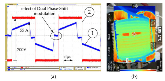
Figure 9.
Primary MFT current iTR (25 A/div) and drain-source voltage vDS (100 V/div) of the SiC MOSFET of the DAB DC-DC converter operating with 20 kHz switching frequency and the DPS modulation (20 µs/div) (a); temperature measurement of the amorphous alloy core and observed heating of individual coils as a result of the proximity effect at rated power (b).
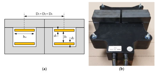
Figure 10.
Main dimensions (a); and the overall view (b) of the second developed MFT with a split planar litz-wire windings placed coaxially one above the another in the disc arrangement.
To minimize the desired Ac of the second MFT prototype, the switching frequency of the DC-DC DAB converter has been increased from 20 kHz to 30 kHz. Six pairs of U126/91/20 and I126/20 cores, i.e., three core stacks and litz wires comprised of 700 strands with a thickness of 0.2 mm have been used in the second MFT prototype. The effective surface of the used litz wires is 22 mm2. The transformers were placed in separate chambers inside the DC PETT housing and are cooled by air blown by fans. The used forced cooling enables the maximum permissible current density of 4 A/mm2 [26] and the windings of the second prototype can carry a maximum current of 88 A. The used planar winding technology enables to adjust the leakage inductance of the transformer very precisely and reproducibly by using insulation distances between the primary and secondary windings.
The application of standard U-type and I-type ferrite core profiles for the core construction enables the use of prefabricated windings and supporting trays made of insulation material. To achieve isolation level of 9 kV, which is two times of the maximum DC-rail traction voltage level, casting the windings by the epoxy resin has been applied. The primary and secondary coils of the second prototype have the same height hw, measured in the direction of the core window width. Hence it fulfils the precondition for the application of the method of Rogowski (Equation (2)) for prediction of leakage inductance [36]. Specifications of the second MFT prototype are listed in Table 5. Figure 10 shows the dimensions of the windings and view of the first developed MFT prototype.
Table 5.
Second MFT prototype specification.
The windings were cast with a resin of good thermal conductivity and high mechanical strength, thanks to which the transformer can be placed in the so-called dirty area of the DC PETT housing. The final volume of the whole transformer is:
With a power density of 3.5 kW/dm3 (≈5 kW/dm3 peak). In order to carry out transformer thermal measurements a thermal camera has been used to determine the core and winding temperature distribution. The transformer has been running for 2 h at rated load. Figure 11 describes the thermal characterization of the transformer operating at a power of 45 kW without forced cooling.
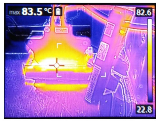
Figure 11.
Temperature measurement of the second developed MFT with split windings at power of 45 kW without forced cooling.
In of the second MFT prototype, with the split windings, the dimension of both the primary and the secondary windings are equal, which provides presenting equal dc resistances, while in the first prototype with the concentric windings the length difference between interior and exterior windings was considerable. The realized 30 kHz MFT prototype has been successfully tested at various operating conditions in a full power rated DAB DC-DC converter, which will be presented in detail in Section 5.3.
5. Control Strategy and Controller Hardware
5.1. Main Control Tasks
As mentioned in Section 2, DC PETT carries out independent control tasks at its output and input, which consist in precisely generating the PWM voltage supplying the traction motor and maintaining full control over the current drawn from the railway overhead contact line. The PWM voltage which feeds the asynchronous motor must be generated in accordance with current tasks of the drive system: control of the electromagnetic torque, which determines the driving dynamics, and control of the magnetic excitation of the motor, which determines the energy consumption.
5.2. Control of the 19-Level H-Bridge 4QC
The presence of galvanic isolation in the DC intermediate circuit and two energy storage elements in each of the power electronic cells, enables independent control of the SiC MOSFET H-bridges on the primary (railway traction) side and secondary (traction motor) side. As mentioned, the nine SiC MOSFET H-bridges of the DC PETT input stage are connected in series and configured as 19-level H-bridge 4QC ensuring a low ripple amplitude of the current drawn from the 3 kV DC overhead contact line. Each H-bridge of the input stage has a capacitor at the output, which plays a role on the DC voltage source: vDC_pri-U1, vDC_pri-U2, …, vDC_pri-V1, …, vDC_pri-W3 for nine individual DAB DC-DC converters. The proposed control scheme of the DC PETT input stage is illustrated in Figure 12.
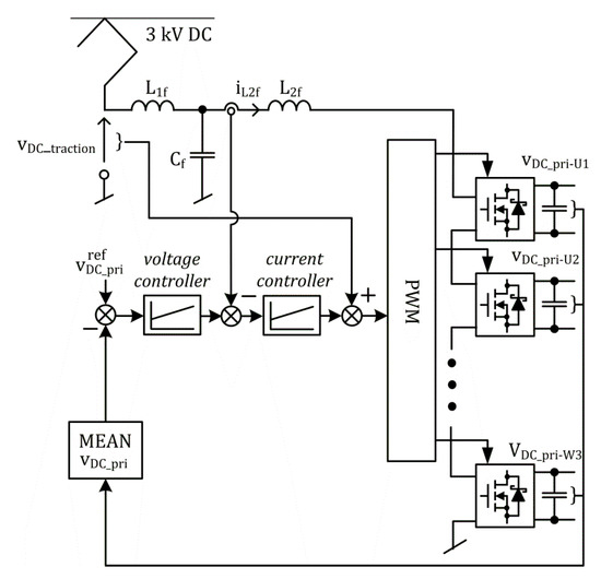
Figure 12.
The overall control scheme for the DC PETT input stage.
The 19-level H-bridge 4QC controller has two closed control loops: the voltage controller to deal with the primary DC voltage vDC_pri of the nine SiC MOSFET H-bridges and the current controller for the purpose to control the input current iL2f. The set value for the voltage controller is the desired DC voltage value at the individual capacitors of the H-bridges. The voltage regulator amplifies and integrates the deviation between the voltage set point on a single capacitor and the average value of the voltages measured across the capacitors of all H-bridges. The voltage regulator output signal is the set point value to the current regulator. The output of the current regulator corrected by the actual value of the traction voltage vDC_traction, measured on the traction current collector, constitutes the set signal to the PWM modulator. The control method described in [36] was used to control individual SiC MOSFET H-bridges of the 19-level 4QC from Figure 12. The essence of the operation of the entire 19-level H-bridge 4QC is that the energy from individual capacitors CDC_pri-U1, CDC_pri-U2, …, CDC_pri-V1, …, CDC_pri-W3 is transferred through isolated DAB DC-DC converters to the three-phase seven-level CHB traction inverter supplying the traction motor. The energy flow from primary DC capacitor of the input H-bridge through the DAB DC-DC converter to the output H-bridge of the U, V or W phase of the CHB traction inverter reduces the voltage on this capacitor. During each control program execution sequence, the individual H-bridges of the input stage, whose intermediate DC circuit voltage reaches the lowest values, are activated, causing the primary DC capacitors to charge and the voltage on these capacitors to rise. The sequence of switching individual cells on and off depends on the current DC voltage levels of individual capacitors CDC_pri-U1, CDC_pri-U2, …, CDC_pri-V1, …, CDC_pri-W3. On the other hand, in the case of energy recuperation, the bridges with the highest voltage value on the DC capacitors are connected to the overhead contact line.
All the electronic circuits of the 4QC-DAB-DC/AC power electronic cells are designed with the floating ground. The ground planes of the electronic circuits of each 4QC H-bridge shown in Figure 12 is connected to the middle points of the DC-links adjacent H-bridges through the resistive dividers. These resistive dividers acts simultaneously as the bleeder resistors for the DC-link capacitors of the power electronic cells. Thanks to this, the full voltage appearing on the electronic circuits will never exceed several hundred volts and the use of optically isolated op-amps with maximum working insulation voltage of 1 kV is sufficient. All electronic circuits are powered from the train’s on-board 24 V DC auxiliary power converter via isolated DC-DC power supplies. These isolated DC-DC power supplies must be able to withstand the full voltage of the 3 kV DC overhead traction line. The measurement of the DC traction voltage vDC_traction required in the control system from Figure 12 is performed using voltage divider placed on a separate insulated electronic board. Measured signal is transmitted to the MASTER controller via optical fiber. The voltage measurement electronic board is supplied by the on-board 24 V DC auxiliary power converter via an isolated DC-DC power supply. By using high-voltage insulation of the cable connecting the L1f and L2f input filter chokes, the iL2f input current measurement is performed using a conventional current transducer. The measuring signal from the current transducer is transmitted directly to the MASTER controller interface board.
5.3. Control of DAB DC-DC Converters
As can be seen from Figure 3 in Section 2, nine DAB DC-DC converters are used to transfer the electrical energy between the primary DC links (CDC_pri-U1, CDC_pri-U2, …, CDC_pri-V1, …, CDC_pri-W3) of the 19-level 4QC and the secondary DC links (CDC_sec-U1, CDC_sec-U2, …, CDC_sec-V1, …, CDC_sec-W3)of the three-phase seven-level CHB traction inverter. Individual DAB DC-DC converters are controlled independently and no information exchange about the control process with the 19-level 4QC, seven-level CHB traction inverter and other DAB DC-DC converters is needed. The single DAB DC-DC converter is shown in Figure 13. The control system of the DAB DC-DC converter is designed to obtain the same voltages on the primary DC-link capacitor and secondary DC-link capacitor vDC_sec = vDC_pri. As a result, each DAB DC-DC converter equalizes the individual DC-link voltages of the 19-level 4QC and the seven-level CHB traction inverter [36].
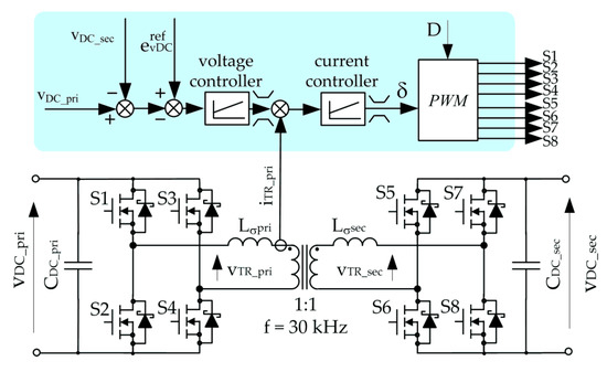
Figure 13.
The single DAB DC-DC converter and its control system.
The DC voltages: vDC_pri on the primary side and vDC_sec on the secondary side are converted into high frequency rectangular pulses vTR_pri and vTR_sec, with constant (D = const) or modulated (D = var) pulse width. The transferred power depends on the mutual phase shift ratio δ between primary and secondary voltages vTR_pri and vTR_sec. For simple phase-shift control transferred power PDAB is defined by (1). Tests in the DAB DC-DC converter with the second MFT prototype were done at 640/640 V and powers of 10 kW, 38 kW and 45 kW for switching frequency of 30 kHz and a dead time 500 ns. Figure 14a shows the characteristic waveforms of the developed DAB DC-DC converter operating at rated power of 38 kW: the primary transformer current iTR_pri (25 A/div), the primary transformer voltage vTR_pri (500 V/div) and the secondary transformer voltage vTR_sec (500 V/div). Figure 14b shows the impact of the dead time on the time duration of the voltage pulses of the primary and secondary transformer voltages vTR_pri and vTR_sec. Although both voltages are controlled with the same constant value of the duty cycle D = 0.96, the voltage pulses of the secondary voltage vTR_sec are longer than voltage pulses of vTR_pri. It can be seen from Figure 14, that in the time period when vTR_pri = vTR_sec = 0 there is no resultant voltage forcing the dynamics of the current and the dynamics of transformer current changes decreases for a fraction of a microsecond. This phenomenon was also recorded when the tested DAB DC-DC converter was operated with a reduced power of 10 kW (Figure 15a). After applying the correction of the duty cycle and taking into account the dead time effect, the above did not occur any more—which can be seen in Figure 15b describing the primary and secondary transformer voltages and current of the DAB DC-DC converter operating with a power of 45 kW.
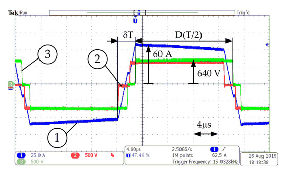
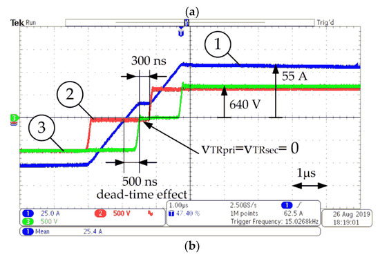
Figure 14.
Measured waveforms of the DAB DC-DC converter with the second MFT prototype: primary transformer current iTR_pri (1), 25 A/div; primary voltage vTR_pri (2), 500 V/div; secondary voltage vTR_sec (3), 500 V/div at the rated load. Time scale 4 µs/div. (a) and 1 µs/div. (b).
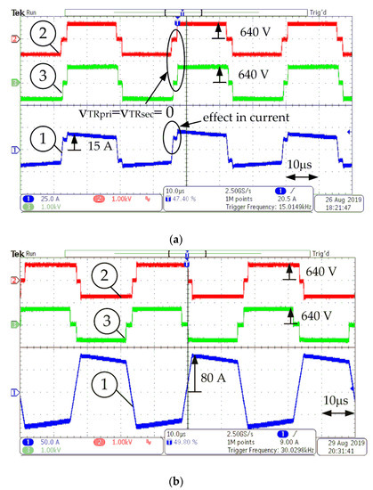
Figure 15.
Measured waveforms of the DAB DC-DC converter with the second MFT prototype: primary transformer current iTR_pri (1), 25 A/div; primary voltage vTR_pri (2), 500 V/div; secondary voltage vTR_sec (3), 500 V/div at partial power of 10 kW (a) and the corresponding waveforms at power of 45 kW (b).
Figure 15a shows the characteristic waveforms of the developed DAB DC-DC converter operating at partial power of 10 kW: the primary transformer current iTR_pri (25 A/div), the primary transformer voltage vTR_pri (1 kV/div) and the secondary transformer voltage vTR_sec (1 kV/div). Figure 15b shows the primary transformer current iTR_pri (50 A/div), the primary transformer voltage vTR_pri (1 kV/div) and the secondary transformer voltage vTR_sec (1 kV/div) for the DAB DC-DC converter with the second MFT prototype overloaded with a power of 45 kW. The efficiency of the DAB DC-DC converter has been calculated using the voltages and currents measurements and the math functions of the digital oscilloscope Tektronix DPO4104. The measured resistances of the primary and secondary windings of the MFT was 11 mΩ and 12 mΩ, respectively. The experimental efficiency results are presented in Figure 16. The developed DAB DC-DC converter characterizes peak efficiency above 98 % and has efficiency around 97.5 % in a wide range of the output power.
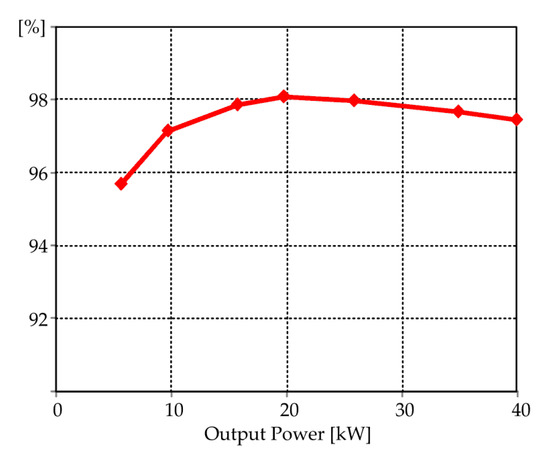
Figure 16.
Measured efficiency versus output power of the DAB DC-DC converter with the second MFT prototype.
5.4. Control of Seven-Level CHB Traction Inverter
As it can be deduced from Figure 3, the seven-level CHB traction inverter is composed of three H-bridges connected in series in any of the phases. The traction inverter is controlled using space vector PWM (SVPWM) by successively activating one H-bridge per phase until the reference voltage vector is reached [36]. The CHB topology enables the operation with advantageously high modulation indexes of individual H-bridges. The DC links of the individual H-bridges are coupled with nine DAB DC-DC converters. If the obtained output voltage is different from the reference motor voltage, the next H-bridge is activated in each phase. At each switching sequence only one H-bridge per phase provides a modulated output voltage, while the others are negatively/positively connected or bypassed [37]. Since their transistors do not switch, they do not generate commutation loses. For the above reason, the control system can consider the topology of the seven-level CHB converter as a set of 3 three-level CHB converters connected in series, which simplifies the control strategy. Each of them is then composed using three H-bridges (one H-bridge in each phase of the inverter) and can be controlled using simple SVPWM patterns [37].
5.5. Control of the Traction Motor
The precision of PWM voltage generation resulting from the seven-level topology of the three-phase traction inverter and the adopted transistor switching frequency of 20 kHz, allows the use of advanced traction motor control algorithms, not previously used in rolling stock. The multiscalar model based control [38,39] has been used to control the torque and excitation of the traction motor. According to the multiscalar model concept, the motor torque is defined as the state variable instead of the current vector component in the q axis that occurs in conventional Field Oriented Control (FOC). The complete multiscalar model (or natural variables [40]) of the induction motor is received after the nonlinear transformation of the stator current and rotor flux vector components occurring in the classic vector model. The multiscalar variables of the induction motor model are selected as follows:
where isα, isβ, ψrα, ψrβ are the stator current and rotor flux vector components, x11 denotes traction motor rotor speed, x12 is proportional to electromagnetic torque, x21 is square of the magnitude of rotor flux vector and represents the excitation of the traction motor, and x22 is a multiscalar variable with no direct physical interpretation and proportional to the reactive power consumption. Figure 17 shows the basic structure of the multiscalar model based control system for the traction motor. The rotor fluxes ψrα, ψrβ, rotor speed (8) and remaining multiscalar variables (9)–(11) are estimated in a speed observer. The variables estimated in the speed observer denoted by Λ are used in the control system. Nonlinear feedback is applied to the system of first-order multiscalar model equations obtained from nonlinear transformation of the multiscalar model [38,39].
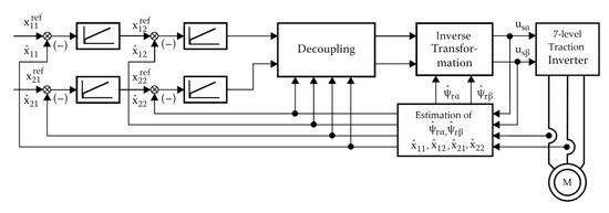
Figure 17.
The basic structure of the multiscalar model based control system for the traction motor.
The approach of using the multiscalar variables (8)–(11) instead of d–q components of the stator current and rotor flux vectors, advantageously eliminates the need for continuous synchronization of the rotating reference frame with the rotating rotor flux vector, which is absolutely required in the FOC method. The use of the linearizing feedback allows to obtain a linear relationship between the outputs and inputs of the multiscalar model and enables decoupled control of the mechanical subsystem of the induction motor, related to the dynamics of the shaft rotational speed x11, and the electromagnetic subsystem, related to the dynamics of the square of the rotor flux vector module x21. Hence, the x21 reference value for the control system from Figure 17 can be modulated according to the arbitrary chosen efficiency optimizing formulation, which ensures the improved efficiency of the traction drive [40]. A detailed analysis of the multiscalar control of the traction motor is beyond the scope of this article and will be discussed in more detail in the forthcoming papers.
5.6. Controller Hardware
For implementing the proposed control strategy a DSP-based MASTER controller board and ten ARM processor-based SLAVE controller boards have been designed as shown in Figure 18 with the features of advanced functionalities and fast execution time. As shown in the Figure 18a, the MASTER controller board consists of a digital signal processor (ADSP-21363) control card, including a FPGA (FPGA-CYCLONE II EP2C8F256) and additional ARM Cortex-M4 32b processor (STM32F407IGT6) control card. The ADSP-21363 floating-point signal processor (3 Mb SRAM, 333 MHz, 2GFLOPS) implements the traction motor torque and excitation control, and the traction line current and voltage control, while the STM32F407IGT6 processor (MCU + FPU, 210DMIPS, 1MB Flash/192 + 4KB RAM, USB OTG HS/FS, Ethernet) realizes human-machine interfacing (HMI) and the communication with other STM32F407IGT6 ARM Cortex-M4 32b processors of nine power electronic cells.
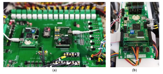
Figure 18.
MASTER controller board consisting of main ADSP-21363 based control card and the auxiliary STM32F407IGT6 Arm Cortex based control card (a); one of nine STM32F407IGT6 Arm Cortex based SLAVE controller boards controlling nine 4QC-DAB-DC/AC power electronic cells (b).
The DSP-based MASTER controller board receives the measurements from 4QC-DAB-DC/AC power electronic cells and implements the traction motor control and traction line voltage and current control algorithms. The FPGA receives the input DC voltage and three-phase output voltage commands from the DSP and implements the PWM algorithm and outputs nine command signals to ARM-based SLAVE controller boards, shown in Figure 18b, via optical fibers. The individual ARM-based SLAVE controller boards receive a command from the MASTER controller board and implement PWM times and outputs gate signals to the transistors. Ten SLAVE controller boards output gate signals to 72 SiC MOSFET dual power modules. To ensure complete isolation between the input stage and the output stage of the DC PETT, one SLAVE controller controls the SiC MOSFET H-bridges of the input sides of the two 4QC-DAB-DC/AC power electronic cells, while the other SLAVE controller controls the transistor bridges of the output sides of these two 4QC-DAB-DC/AC power electronic cells. Both SLAVE controllers communicate with each other using fiber optics.
The MASTER controller board and all SLAVE controller boards contain signal conditioning circuits designed to receive individual voltage and current sensors signals and send them to the DSP or ARM processors respectively. The isolated communication interfaces are realized by a serial Controller Area Network (CAN) interface port.
The overall MASTER control commands of the DSP can be received in two modes: from the driver’s console in the train driver’s cab (train running mode) and from the operator’s PC through the DSP CAN port (service mode). The execution period of one cycle of the control scheme in the main DSP is 150 μs, while the FPGA on the MASTER control card works with a three times shorter execution period of the PWM algorithm. Individual FPGAs on SLAVE controller boards operate with the execution period equal to 33.33 μs. The accuracy of the PWM time counting on the SLAVE controller board results from the used 150 MHz clock.
The control relay outputs on the main-board shown in Figure 18a are used to control the train’s individual switching devices, such as the circuit breaker circuit or the contactor circuits in the on-board high-voltage switchgear.
6. On-Track Testing
The developed DC PETT prototype for the railway applications has been assembled as shown in Figure 4 in Section 2. Due to the direct availability of the 3 kV DC railway network on the railway siding, a number of experiments were conducted with the developed DC PETT prototype mounted on the roof of the EN81 series electric passenger railcar shown in Figure 2 in the introductory section. During the tests, only one drive set of the traction motor powered by the developed 3kV DC PETT was running, which made it possible to obtain measurement results specifically for one complete drive system. The second traction motor of the EN81 series electric passenger railcar was not running during the tests. Due to the limitation of the track length, the maximum achievable speed during the experiments was, however, limited and did not reach the operating speed of 120 km/h given by the manufacturer of the rail vehicle. The route of the test runs with a length of 600 m on the Bydgoszcz-Towarowa railway siding used during on-track testing is shown in Figure 19.
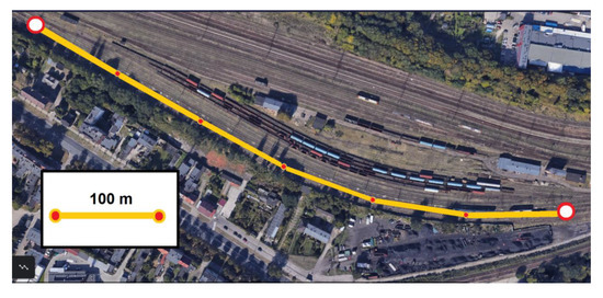
Figure 19.
The route of test runs with a length of 600 m on the Bydgoszcz-Towarowa railway siding.
Specifications of the DKLBZ 0910-04 type traction motor of the EN81 series electric passenger railcar are listed in Table 6.
Table 6.
DKLBZ 0910-04 type traction motor specification.
The results of the track test run on 600 m railway siding are shown in Figure 20. The recorded waveforms were saved on a PC connected to the DSP-based MASTER controller card via USB.
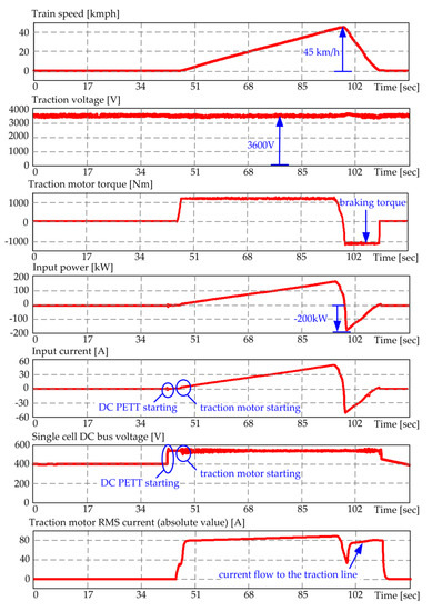
Figure 20.
Track test results: Recorded waveforms during start-up of the train with the DC PETT based asynchronous traction drive to a speed of 45 km/h and immediate braking. Top to bottom: (1) train speed; (2) traction motor torque; (3) DC PETT input power; (4) DC PETT input current; (5) traction DC voltage; (6) primary DC bus voltage of a single 4QC-DAB-DC/AC power electronic cell.
Figure 20 illustrates recorded waveforms during accelerating of the train with the DC PETT based asynchronous traction drive to the speed of 45 km/h and immediate braking. Before the connection of the DC PETT to the overhead traction line voltage there is no energy stored in the DC PETT and all DC links are empty. Similar to AC PETT reported in [19], initial charging is performed from the DC side utilizing the startup resistor that is bypassed later on. Moreover, the developed DC PETT has a second mode of pre-charging the intermediary circuits from the on-board battery bank using a set of DC-DC converters. The latter mode enables the DC PETT to be connected to the overhead traction line without any inrush current.
Referring to Figure 20, after the train pantograph is on, the uncontrolled voltage on each of the primary DC links equals the overhead line voltage divided by nine. Then, after starting DC PETT, the primary DC-link voltage is controlled to 520 V and the secondary DC-link voltage is controlled to be equal primary DC-link voltage. During DC PETT operation the input current drawn from the overhead traction line is controlled according to the control scheme shown in Figure 14. In all experiments, the power recovered during braking was transferred back to the traction network. As can be seen from Figure 20, the delivery of braking power of the order of 200 kW to the traction network did not significantly change the voltage of the traction network.
Figure 21 shows the characteristic traction motor stator current and the PWM output voltage waveforms obtained during three different operation modes of the DC PETT. Figure 21a shows the stator current waveform during start-up and the acceleration of the traction motor (50 A/div; 1 s/div). Thanks to the use of high-performance torque control, mentioned in Section 5, the stator current magnitude is limited at the desired value and its amplitude does not exceed 100 A at all times.
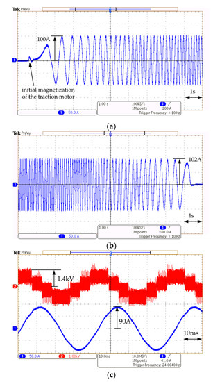
Figure 21.
Traction motor stator current and output PWM voltage waveforms obtained during three operation modes of the DC PETT: start-up and acceleration mode (a); braking (b); phase voltage and phase current of the traction motor steady-state operation (c).
As can be seen, there are no undesirable oscillations in the current waveform. Figure 21b shows the stator current waveform during the final braking phase of the train from 15 km/h until the train stops (50 A/div; 1 s/div). Figure 21c shows the stator current and the PWM voltage at the DC PETT output in the steady-state operation of the traction motor (50 A/div; 1 kV/div; 10 ms/div). As it is shown in Figure 21c, the applied three-phase, seven-level CHB topology provides an almost sinusoidal PWM voltage, which has not been demonstrated in any other 3kV DC rail traction inverter so far. By using CHB technology, the instantaneous maximum value of the voltage switched by the SiC MOSFET transistors does not exceed a few hundred volts. At high switching speeds of SiC MOSFET transistors, this will significantly facilitate compliance with the stringent requirements of railway electromagnetic compatibility (EMC) standards, which will be the focus of the planned continuation of the work carried out by the authors.
The efficiency of the SiC-based 3kV DC PETT prototype has been measured. As in [19], the power consumption of the auxiliary converters supporting the cooling system and the control system has not been included in the efficiency calculations. The plots of efficiencies versus output power are shown in Figure 22.
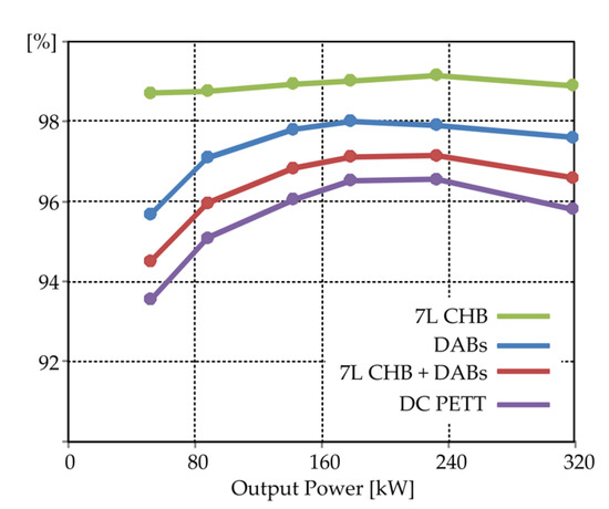
Figure 22.
Measured efficiency versus output power of the three power stages and the entire 3kV DC PETT prototype.
As can be seen from Figure 22, the three-phase seven-level CHB traction inverter (7L CHB), considered separately, characterizes peak efficiency around 99%, which is comparable to the corresponding SiC based MV multilevel CHB inverters constructed from low-voltage SiC MOSFET transistors, presented in the literature [22]. The efficiency of the 4QC input stage is slightly higher than that of the seven-level CHB traction inverter, because when cascaded H-bridges operate with a constant voltage of 3kV DC overhead traction line, actually only two SiC MOSFETs work in each H-bridge. However, thanks to the use of the full H-bridges in the DC PETT input stage instead of half bridges, it is possible that the developed SiC-based DC PETT can also work with an AC input voltage, as is the case with multi-system locomotives. However, the operation of the proposed SiC-based DC PETT in an AC voltage system is beyond the scope of this paper and will be the subject of future publications. As can be seen in Figure 22, the isolation stage ensured by nine DAB DC-DC converters has the greatest impact on the efficiency of the entire SiC-based DC PETT. The SiC-based DC PETT prototype has an efficiency of around 96% in a wide range of output power and the peak efficiency around 96.5%.
7. Conclusions
The design and development of the SiC-based DC PETT intended for EMUs operated in 3 kV DC rail traction have been presented in this paper. The developed DC PETT has been implemented into the PESA 308 EN81 series electric passenger railcar that operates in Polish regional passenger rail transport. The conducted experimental tests during train runs on the trial confirm the full functionality of the developed device.
As with the MV PETT for AC traction [19], the proposed DC PETT offers a number of advantages that make it very attractive for rolling stock operating in 3 kV DC traction. First of all, in the era of widespread striving to design highly efficient and ultra-quiet drive converters from SiC semiconductor devices, the proposed solution has a number of advantages if one compares it to high-voltage SiC traction inverters with a classic design being currently at the stage of analyzes and preliminary tests. Conventional two-level voltage source traction inverters of the working voltage in the catenary 3 kV DC would contain SiC MOSFET transistors with a voltage blocking of 6 kV, and the conventional three-level inverter voltage would contain SiC MOSFET transistors with a voltage blocking of 3 kV. It is already known that obtaining high voltage switching frequencies SiC MOSFET above 5 kHz is energy inefficient and the management of electromagnetic disturbances at such high switched energies is quite a challenge. The component modules of the proposed DC PETT, in the form of nine 4QC-DAB-DC/AC power electronic cells, are made with the use of low-voltage SiC technology (1200 V). The applied high switching frequency: 30 kHz to 1.2 kV SiC MOSFETs used in DAB DC-DC converters and 20 kHz to 1.2 kV SiC MOSFETs used in SiC MOSFET H-bridges of the input and output stage, do not cause as significant energy losses as it would be in the case of high voltage (>3 kV) SiC MOSFET technology. The applied high switching frequency allows for favorable elimination of noise from the converter operation. Moreover, the use of multi-level topology made it possible to follow the command voltage from the control system with very high precision and, therefore, enables the application of the high precision control of the traction motor. Moreover, compared to classical topologies, the applied active input stage with the regulator of the current drawn from the overhead line enables the minimization of the input LC filter and, thus, minimization of the total volume and cost, which the authors intend to make the subject of detailed analysis in future publications.
The MFT design path, discussed in detail in the article, shows that the important factors influencing the power density of the developed transformers are the provision of appropriate insulation gaps to ensure galvanic isolation at the level of 9 kV DC and the provision of structural gaps between the windings to obtain the desired transformer leakage inductance. In the case of the traction drive investigated in the paper, with a relatively small power of 325 kVA (500 kVA in peak), the power density of the designed 38 kW MFT was 3.5 kW/dm3 (≈5 kW/dm3 peak). This allows the authors to reasonably hope that for a higher power MFT, the power density obtained will also be higher. At the present stage, it is difficult to compare the power density of the developed 3kV DC PETT prototype with a built-in lightweight LCL input traction filter with 3 kV DC roof-mounted traction inverters available on the market because the solutions known to the authors have a heavy external traction filter mounted in a separate container, which is not taken into account by manufacturers to estimating the power density of the traction converter. The developed 3kV SiC-based DC PETT prototype, thanks to the built-in 4QC power input stage, is immediately ready for cooperation with the AC traction network in a multi-system EMUs. The proposed modular DC PETT structure, composed of the same repeatable power electronic cells, could ensure lower maintenance costs, short inspection and repair times for potential faults, and thus high availability - required in the rolling stock.
Author Contributions
Conceptualization, M.A.; software, J.S.; validation, M.A., J.S.; investigation, M.A., J.S.; writing—original draft preparation, M.A.; writing—review and editing, M.A., J.S.; visualization, M.A.; All authors carried out the theoretical analysis and contributed to writing the paper. All authors have read and agreed to the published version of the manuscript.
Funding
The authors gratefully acknowledge financial support from the European Union under the Polish Operational Programme Smart Growth, The National Centre for Research and Development, Grant no. POIR.01.02.00-00-0193/16-00. The APC was funded by Gdańsk University of Technology.
Acknowledgments
The authors acknowledge the commitment and resources provided by MMB Drives Ltd., H.Cegielski-Energocentrum Ltd. and PESA Bydgoszcz S.A. during the research. The authors would like to thank Jędrzej Pietryka, Sebastian Giziewski and Patryk Kruk for their valuable support in writing this article.
Conflicts of Interest
The authors declare no conflict of interest.
References
- Brenna, M.; Foiadelli, F.; Zaninelli, D. Electrical Railway Transportation Systems; IEEE Press Series on Power Engineering; John Wiley & Sons, Inc.: Hoboken, NJ, USA, 2018. [Google Scholar]
- Ronanki, D.; Singh, S.A.; Williamson, S.S. Comprehensive topological overview of rolling stock architectures and recent trends in electric railway traction systems. IEEE Trans. Transp. Electrif. 2017, 3, 724–738. [Google Scholar] [CrossRef]
- Falco, M.; Desportes, G.; Piton, M. Innovative Railway Traction System. In Proceedings of the 7th Transport Research Arena (TRA 2018), Vienna, Austria, 16–19 April 2018; pp. 1–10. [Google Scholar]
- Ishikawa, K.; Terasawa, K.; Sakai, T.; Sugimoto, S.; Nishino, T. Development of rolling stock inverters using SiC. Hitachi Rev. 2017, 2, 155–160. [Google Scholar]
- Rujas, A.; Lopez, V.M.; Villar, I.; Nieva, T.; Larzbal, I. SiC-hybrid based railway inverter for metro application with 3.3kV low inductance power modules. In Proceedings of the IEEE Energy Conversion Congress and Exposition (ECCE 2019), Baltimore, MD, USA, 29 September–3 October 2019; pp. 1992–1997. [Google Scholar]
- Lindahl, M.; Velander, E.; Johansson, M.H.; Blomberg, A.; Nee, H.P. Silicon Carbide MOSFET Traction Inverter Operated in the Stockholm Metro System Demonstrating Customer Values. In Proceedings of the IEEE Vehicle Power and Propulsion Conference (VPPC 2018), Chicago, IL, USA, 27–30 August 2018; pp. 1–6. [Google Scholar]
- Schmidt, E.; Müllner, F.; Neudorfer, H. Modelling and Precalculation of Additional Losses of Inverter Fed Asynchronous Induction Machines for Traction Applications. In Proceedings of the International Aegean Conference on Electrical Machines and Power Electronics and Electromotion, Istanbul, Turkey, 8–10 September 2011; pp. 1–6. [Google Scholar] [CrossRef]
- Dangl, F.; Neudorfer, H. Impact of Additional Losses due to Inverter Supply on the Thermal Behaviour of Induction Machines for Traction Drives. Elektrotechnik Inf. 2016, 1, 27–35. [Google Scholar]
- Bakran, M.M.; Eckel, H.G. Power Electronics Technologies for Locomotives. In Proceedings of the IEEE Power Conversion Conference (PCC 2007), Nagoya, Japan, 2–5 April 2007; pp. 1362–1368. [Google Scholar] [CrossRef]
- Soltau, N.; Wiesner, E.; Hatori, K.; Uemura, H. 3.3 kV Full SiC MOSFETs—Towards High-Performance Traction Inverters. Bodos Power Syst. 2018, 1, 22–24. [Google Scholar]
- Steczek, M.; Szeląg, A.; Chatterjee, D. Analysis of disturbing effect of 3 kV DC supplied traction vehicles equipped with two-level and three-level VSI on railway signalling track circuits. Bull. Pol. Acad. Sci. 2017, 65, 663–674. [Google Scholar] [CrossRef]
- Das, M.K.; Capell, C.; Grider, D.E.; Leslie, S.; Ostop, J.; Raju, R.; Schutten, M.; Nasadoski, J.; Hefner, A. 10 kV, 120 A SiC half H-bridge power MOSFET modules suitable for high frequency, medium voltage applications. In Proceedings of the IEEE Energy Conversion Congress and Exposition (ECCE 2011), Phoenix, Arizona, 17–22 September 2011; pp. 2689–2692. [Google Scholar]
- Aceiton, R.; Weber, J.; Bernet, S. Input filter for a power electronics transformer in a railway traction application. IEEE Trans. Ind. Electron. 2018, 65, 9449–9458. [Google Scholar] [CrossRef]
- Rufer, A.; Schibli, N.; Chabert, C.; Zimmermann, C. Configurable front-end converters for multicurrent locomotives operated on 16 2/3 Hz AC and 3 kV DC systems. IEEE Trans. Power Electron. 2003, 18, 1186–1193. [Google Scholar] [CrossRef]
- Stackler, C.; Morel, F.; Ladoux, P.; Fouineau, A.; Wallart, F.; Evans, N. Optimal sizing of a power electronic traction transformer for railway applications. In Proceedings of the 44th Annual Conference of the IEEE Industrial Electronics Society (IECON 2018), Washington, DC, USA, 20–23 October 2018; pp. 1380–1387. [Google Scholar] [CrossRef]
- Morel, F.; Stackler, C.; Ladoux, P.; Fouineau, A.; Wallart, F.; Evans, N.; Dworakowski, P. Power electronic traction transformers in 25 kV/50 Hz systems: Optimisation of DC/DC Isolated Converters with 3.3 kV SiC MOSFETs. In Proceedings of the International Exhibition and Conference for Power Electronics, Intelligent Motion, Renewable Energy and Energy Management (PCIM Europe 2019), Nurnberg, Germany, 7–9 May 2019; pp. 1–9. [Google Scholar]
- Tremong, J.-F.; Vulturescu, B.; Chamaret, A.-P. Evaluation of the energy saving potential of a Power Electronic Transformer for rolling stock under 25kV, 50Hz. In Proceedings of the 7th Transport Research Arena (TRA 2018), Vienna, Austria, 16–19 April 2018; pp. 1–9. [Google Scholar]
- Farnesi, S.; Marchesoni, M.; Passalacqua, M.; Vaccaro, L. Solid-State Transformers in Locomotives Fed through AC Lines: A Review and Future Developments. Energies 2019, 12, 4711. [Google Scholar] [CrossRef]
- Zhao, C.; Dujic, D.; Mester, A.; Steinke, J.K.; Weiss, M.; Lewdeni-Schmid, S.; Chaudhuri, T.; Stefanutti, P. Power electronic traction transformer—Medium voltage prototype. IEEE Trans. Ind. Electron. 2014, 61, 3257–3268. [Google Scholar] [CrossRef]
- Huber, J.E.; Kolar, J.W. Optimum number of cascaded cells for high-power medium-voltage AC–DC converters. IEEE J. Emerg. Sel. Top. Power Electron. 2017, 5, 213–232. [Google Scholar] [CrossRef]
- Magro, M.C.; Savio, S. Reliability and availability performances of a universal and flexible power management system. In Proceedings of the IEEE International Symposium on Industrial Electronics (ISIE 2010), Bari, Italy, 4–7 July 2010; pp. 2461–2468. [Google Scholar] [CrossRef]
- Pan, J.; Ke, Z.; Al Sabbagh, M.; Li, H.; Potty, K.; Perdikakis, W.; Na, R.; Zhang, J.; Wang, J.; Xu, L. 7-kV, 1-MVA SiC-Based Modular Multilevel Converter Prototype for Medium-voltage Electric Machine Drives. IEEE Trans. Power Electron. 2020, 35, 10137–10149. [Google Scholar] [CrossRef]
- Engelmann, G.; Sewergin, A.; Neubert, M.; De Doncker, R.W. Design Challenges of SiC Devices for Low- and Medium-Voltage DC-DC Converters. In Proceedings of the IEEE International Power Electronics Conference (IPEC-Niigata 2018 -ECCE Asia), Niigata, Japan, 20–24 May 2018; pp. 3979–3984. [Google Scholar] [CrossRef]
- Adamowicz, M.; Giziewski, S.; Pietryka, J.; Krzeminski, Z. Performance comparison of SiC Schottky diodes and silicon ultra fast recovery diodes. In Proceedings of the 7th IEEE International Conference-Workshop Compatibility and Power Electronics (CPE 2011), Tallin, Estonia, 1–3 June 2011; pp. 144–149. [Google Scholar]
- Leibl, M.; Ortiz, G.; Kolar, J.W. Design and experimental analysis of a medium-frequency transformer for solid-state transformer applications. IEEE J. Emerg. Sel. Top. Power Electron. 2017, 5, 110–123. [Google Scholar] [CrossRef]
- Villar, I. Multiphysical Characterization of Medium-Frequency Power Electronic Transformers. Ph.D. Thesis, École Polytechnique Fédérale de Lausanne, Lausanne, Switzerland, 2010. [Google Scholar]
- Shua, P.; Biela, J. Influence of material properties and geometric shape of magnetic cores on acoustic noise emission of medium-frequency transformers. IEEE Trans. Power Electron. 2017, 32, 7916–7931. [Google Scholar] [CrossRef]
- Jain, A.K.; Ayyanar, R. PWM control of dual active bridge: Comprehensive analysis and experimental verification. IEEE Trans. Power Electron. 2011, 26, 1215–1227. [Google Scholar] [CrossRef]
- Villar, I.; Mir, L.; Etxeberria-Otadui, I.; Colmenero, J.; Agirre, X.; Nieva, T. Optimal design and experimental validation of a medium-frequency 400 kVA power transformer for railway traction applications. In Proceedings of the IEEE Energy Conversion Congress and Exposition (ECCE), Raleigh, NC, USA, 15–20 September 2012; pp. 684–690. [Google Scholar] [CrossRef]
- Everts, J. Modeling and Optimization of Bidirectional Dual Active Bridge ac-dc Converter Topologies. Ph.D. Thesis, Arenberg Doctoral School Faculty of Engineering Science, KU Leuven, Leuven, Belgium, 2014. [Google Scholar]
- Adamowicz, M. Power Electronics Building Blocks for implementing SmartMV/LV Distribution Transformers for Smart Grid. Acta Energetica 2014, 4, 6–13. [Google Scholar] [CrossRef]
- Saeed, M.; Rogina, M.R.; Rodriguez, A.; Arias, M.; Briz, F. SiC-Based High Effciency High Isolation Dual Active Bridge Converter for a Power Electronic Transformer. Energies 2020, 13, 1198. [Google Scholar] [CrossRef]
- Haneda, R.; Akagi, H. Design and Performance of the 850-V 100-kW 16-kHz Bidirectional Isolated DC–DC Converter Using SiC-MOSFET/SBD H-Bridge Modules. IEEE Trans. Power Electron. 2020, 35, 10013–10025. [Google Scholar] [CrossRef]
- Kantor, V.V. Methods of Calculating Leakage Inductance of Transformer Windings. Russ. Electr. Eng. 2009, 80, 224–228. [Google Scholar] [CrossRef]
- Prieto, R.; Cobos, J.A.; Garcia, O.; Alou, P.; Uceda, J. Taking into account all the parasitic effects in the design of magnetic components. In Proceedings of the IEEE Thirteenth Annual Applied Power Electronics Conference and Exposition (APEC’98), Anaheim, CA, USA, 15–19 February 1998; pp. 400–406. [Google Scholar]
- Doebbelin, R.; Teichert, C.; Benecke, M.; Lindemann, A. Computerized calculation of leakage inductance values of transformers. Piers Online 2009, 5, 721–726. [Google Scholar]
- Lewicki, A.; Morawic, M. Structure and the space vector modulation for a medium-voltage power-electronic-transformer based on two seven-level cascade H-bridge inverters. IET Electr. Power Appl. 2019, 13, 1514–1523. [Google Scholar] [CrossRef]
- Krzemiński, Z. Nonlinear control of induction motor. IFAC 1987, 20, 357–362. [Google Scholar] [CrossRef]
- Wilamowski, B.M.; Irwin, J.D. (Eds.) The Industrial Electronics Handbook. Power Electronics and Motor Drives, 2nd ed.; CRC Press, Taylor & Francis Group: Boca Raton, FL, USA, 2011. [Google Scholar]
- Dong, G.; Ojo, O. Efficiency optimizing control of induction motor using natural variables. IEEE Trans. Ind. Electron. 2006, 53, 1791–1798. [Google Scholar] [CrossRef]


Publisher’s Note: MDPI stays neutral with regard to jurisdictional claims in published maps and institutional affiliations. |
© 2020 by the authors. Licensee MDPI, Basel, Switzerland. This article is an open access article distributed under the terms and conditions of the Creative Commons Attribution (CC BY) license (http://creativecommons.org/licenses/by/4.0/).