Article

Performance of Communication Network for Monitoring Utility Scale Photovoltaic Power Plants

by
Ali M. Eltamaly
1,2,3,*,
Mohamed A. Ahmed
4,5,
Majed A. Alotaibi
6,
Abdulrahman I. Alolah
6 and
Young-Chon Kim
7
1
Sustainable Energy Technologies Center, King Saud University, Riyadh 11421, Saudi Arabia
2
Department of Electrical Engineering, Mansoura University, Mansoura 35516, Egypt
3
Saudi Electricity Company Chair in Power System Reliability and Security, King Saud University, Riyadh 11421, Saudi Arabia
4
Department of Electronic Engineering, Universidad Técnica Federico Santa María, Valparaíso 2390123, Chile
5
Department of Communications and Electronics, Higher Institute of Engineering & Technology–King Marriott, Alexandria 23713, Egypt
6
Department of Electrical Engineering, College of Engineering, King Saud University, Riyadh 11421, Saudi Arabia
7
Department of Computer Engineering and Smart Grid Research Center, Jeonbuk National University, Jeonju 561-756, Korea
*
Author to whom correspondence should be addressed.
Energies 2020, 13(21), 5527; https://doi.org/10.3390/en13215527
Submission received: 16 March 2020 / Revised: 9 April 2020 / Accepted: 18 April 2020 / Published: 22 October 2020
(This article belongs to the Section A1: Smart Grids and Microgrids)

Abstract

:
The grid integration of large scale photovoltaic (PV) power plants represents many challenging tasks for system stability, reliability and power quality due to the intermittent nature of solar radiation and the site accessibility issues where most PV power plants are located over a wide area. In order to enable real-time monitoring and control of large scale PV power plants, reliable two-way communications with low latency are required which provide accurate information for the electrical and environmental parameters as well as enabling the system operator to evaluate the overall performance and identify any abnormal conditions and faults. This work aims to design a communication network architecture for the remote monitoring of large-scale PV power plants based on the IEC 61850 Standard. The proposed architecture consists of three layers: the PV power system layer, the communication network layer, and the application layer. The PV power system layer consists of solar arrays, inverters, feeders, buses, a substation, and a control center. Monitoring parameters are classified into different categories including electrical measurements, status information, and meteorological data. This work considers the future plan of PV power plants in Saudi Arabia. In order to evaluate the performance of the communication network for local and remote monitoring, the OPNET Modeler is used for network modeling and simulation, and critical parameters such as network topology, link capacity, and latency are investigated and discussed. This work contributes to the design of reliable monitoring and communication of large-scale PV power plants.

1. Introduction

Saudi Arabia is moving forward toward increasing the grid integration of large-scale photovoltaic (PV) power plants, supported by great opportunities of having long sunshine hours and high solar radiation intensity [1]. Different projects have been scheduled to be constructed, such as Qurrayat (200 MW), Alfaisalia (600 MW), Rabigh (300 MW), Jeddah (300 MW), Saad (300 MW), etc. [2]. These projects are expected to contribute to reducing the use of conventional fossil fuels and decreasing carbon dioxide emissions. Generally, the PV power systems are classified into three main categories: residential, commercial and utility scale. The residential types represent the smallest type of installations, with capacities less than 10 kW, usually used in private properties. The commercial installations are commonly used in commercial buildings with capacities ranging from 10 to 100 kW. This research targets the utility scale PV power plants (solar farms) with capacities above 100 kW [3]. As more and more PV power plants are integrated into the power grid, communication infrastructures will play an important role in the monitoring, protection and control of both PV power plants and the power grid.
Due to the intermittent nature of solar power generation, there are many operational and technical challenges including shading, soiling, cell aging, cell damage, multi-vendor equipment, etc. which make it difficult to identify and troubleshoot the abnormal conditions [3]. As most large-scale PV power plants are installed in remote sites over a large geographic area, communication infrastructures will play an important role in the monitoring, operating and controlling of PV power plants. The communication infrastructures enable the control center operator to detect any fault early before it causes a catastrophic problem, with the aim of increasing the PV power plant availability and decrease the operation and maintenance costs. With the absence of a unified communication architecture, different vendors and solar panel manufacturers are developing their own monitoring and control solutions according to their needs.
There are different configurations and topologies for large-scale PV power plants. The authors in [4] studied large scale PV power plants and provided a detailed description for the main electrical components (PV panels, PV inverters and transformers), the internal PV power plant configuration and the collection grid topologies (radial, ring and star). The authors in [5] presented various power conversion architectures (central inverter, string inverter, multi-string inverter and micro-inverter) and different strategies for reconfigurations of photovoltaic arrays in order to increase the output power under different conditions (mismatch condition and partial shading).
The basic elements of the PV monitoring system are sensors, data transmission, data storage and data analysis. The monitoring system for PV power plant can be divided into different levels: PV module level, string level, array level, and plant level. With respect to the PV module level, in order to enable efficient real-time monitoring and control, detailed information of each panel is required such as current, voltage, irradiance and temperature [6]. The authors in [7] presented a low-cost wireless monitoring system for PV modules in order to give details information for the performance of the PV panels. The collected information includes meteorological and electrical data from the PV system. Different types of sensor nodes are considered including module temperature, solar irradiance, current, and voltage. The authors in [8] developed a wireless solution for the remote monitoring of PV modules based on long range (LoRa) low power wireless area network (LPWAN) communication technology. However, the system performance in [7] and [8] considered a small-scale PV system with a small number of sensor nodes.
There are different studies regarding monitoring the behavior of PV modules and PV power plants. The authors in [9] developed a monitoring circuit which measures the operating voltage and the current of the PV panel. With the developed circuit, the behavior of the PV modules could be identified under normal/shading conditions. The authors in [10] investigated the appropriate number and the position of the irradiance sensors to be installed in large PV power plant. The authors in [11] developed a condition monitoring system for monitoring and control of a photovoltaic system consists of 60 PV modules and three inverters. The monitoring system consists of various sensor nodes including voltage, current and temperature. The communication system is based on ZigBee wireless network technology. The authors in [12] classified the condition monitoring of PV system into different levels including grid level monitoring, inverter level monitoring, array level monitoring, string level monitoring and module level monitoring. Among different monitoring methods, module level monitoring was capable of identifying the location of the faults and abnormality through sensor nodes mounted on PV modules. However, a large volume of data needs to be communicated between PV modules and the control center.
Recently, the application of the internet of things (IoT), computer vision and unmanned aerial vehicle (UAV) have received great attention in remote monitoring of PV power plants. The authors in [13] presented an IoT architecture for remote monitoring of a solar photovoltaic system. The monitoring system consists of a PV module attached with different sensor nodes and measurement devices including pyranometer, voltage, current, temperature, humidity and video camera. The authors in [14] presented the application of computer vision and UAV for remote condition monitoring for photovoltaic systems. The system consists of a drone with a radiometric thermal camera and an algorithm for the detection of hotspots. The authors in [15] investigated hybrid communication networks for distributed energy resources (DER) with the focus on rooftop solar PV panels using network simulator 3 (NS3). The hybrid communication architectures included different technologies such as Ethernet, WiFi and WiMAX, and the performance was evaluated with respect to latency, throughput and packet loss rate. The authors in [16] presented modeling intelligent electric devices (IEDs) for different types of DERs based on IEC 61850 standard and simulation of communication configuration using OPNET Modeler for a microgrid system. The performance of the communication network was evaluated with respect to end-to-end delay and throughput.
Considering the previous research work related to the monitoring system of PV systems, as given in Table 1, there is a knowledge gap regarding the performance of the communication infrastructures associated with monitoring large-scale PV power plants with respect to network topology, network traffic and application definition, which have not received much attention in the literature. This work aims to study the performance of the communication infrastructure associated with remote monitoring and control of large-scale PV power plants. The major elements of a PV power plant are PV arrays, PV inverters, feeders, buses, meteorological masts, substations, and the control center. The communication infrastructure comprises measurement devices (sensor nodes, meters and intelligent electronic devices) and networking components (network switches, cables, and servers). Monitoring parameters are classified into different types: environmental information, status information and electric information based on IEC 61724 standard. In order to design the communication network, many factors should be determined, including the number and types of sensor nodes and the generated amount of data. Network topology, link capacity, and latency are critical parameters investigated and discussed. The main contributions of this research are as follows:
  • Design a communication network architecture for remote monitoring of large scale PV power plants based on the IEC 61850 Standard. The proposed architecture consists of three layers: the PV power system layer, the communication network layer, and the application layer.
  • Classify monitoring parameters into different types: environmental information, status information and electric information based on IEC 61724 standard.
  • Propose a communication model for the PV power system and define data types, data size and the number of sensor nodes.
  • Build communication network models for the PV system using OPNET Modeler and evaluate the network performance with respect to end-to-end delay for a single PV power plant and a group of PV power plants from different regions in Saudi Arabia.

2. Photovoltaic Power Plant Architectures

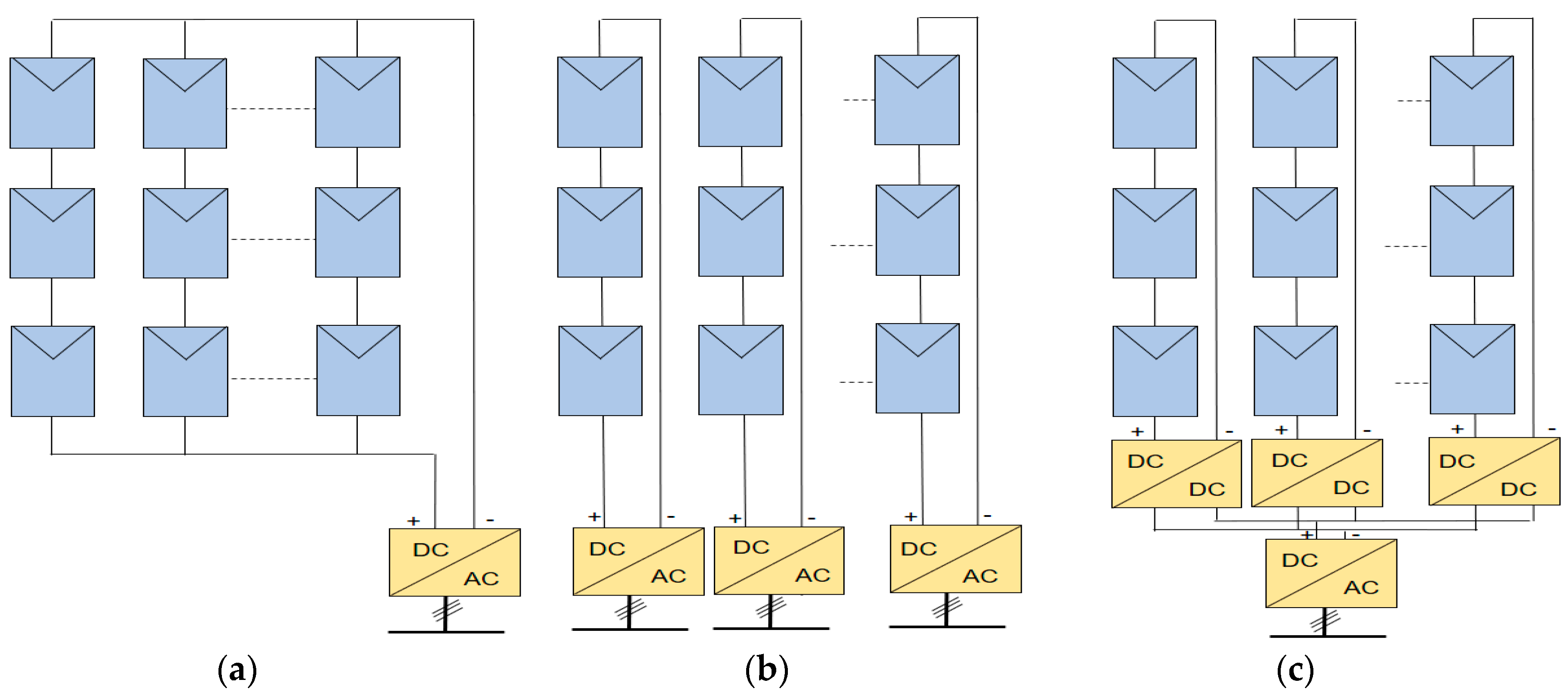
2.1. PV Power System Layer

The basic components of a typical large-scale PV power plant are PV panels, PV inverters, transformers and protection devices [17]. The PV panels (a number of solar cells connected in series and encapsulated with a special frame) convert solar energy into electricity. PV panels are arranged in groups and are connected together to form module strings. If there is a fault in any single module or shading, the output voltage of PV panels will be affected, which may degrade the system output [18]. The outputs from the PV panels are connected to PV inverters. The PV inverters are electronic devices used to allow the conversion from DC to AC. This can be done through one stage (DC/AC) or two stages (DC/DC, DC/AC). Transformers are used to step up the output voltage from the PV inverters and to connect the PV power plant to the grid.
Figure 1 shows different configurations for the interconnection between PV panels and inverters such as central, string and multi-string [4,5]. The selection among different configurations is based on the cost, reliability, and power quality. In the central configuration, all the PV panels are connected to one inverter. The PV panels are clustered into PV arrays. Each PV array consists of many PV strings connected in parallel and each string consists of many PV panels connected in series. In the string configuration, each string is connected to one inverter. In the case of multi-string configuration, the PV strings are connected to a DC/DC converter and each group of DC/DC converters are connected one DC/AC inverter.
The internal topology of a PV power plant represents the electrical connections among PV panels, PV inverters and transformers. Different topologies and configurations could be considered based on output power, cost, and reliability such as central topology, string topology and multi-string topology. There are different configurations for connecting the internal DC collection grid and the AC collection grid, such as radial, star, and ring [4,5].
  • Radial topology considers a group of PV generators connected to one feeder. This topology is simple and cheap but has low reliability. In the case of a fault in the first generator connected to the feeder, all the string will be disconnected.
  • Ring topology is based on the radial topology configuration but adds an extra feeder to the string from the other side. This enables connection to the PV generators even in the case of a PV generator fault. However, this configuration brings more complexity and cost for the installations.
  • Star topology offers higher reliability compared with radial and ring. Each PV generator is connected to the main controller through a feeder connection. The connections between PV generators and feeders increase the total cost of the star topology configuration.

2.2. Data Communication of PV Power Plants

In PV power plants, supervisory control and data acquisition (SCADA) systems play an important role in the remote monitoring and control of field devices (sensors, smart meters, remote terminal units (RTUs), intelligent electric devices (IEDs), etc.) [19,20]. A typical SCADA system consists of data acquisition units, RTUs, communication networks, and system servers. Data acquisition units measure and collect monitoring parameters such as voltage, current, temperature, irradiance, etc., and then transmit it through the communication infrastructure to the control center. As the control center represents the core of the SCADA system, there are several application servers, such as front-end servers, historian servers, web servers and human–machine interfaces, where monitoring data are analyzed and visualized. The front-end servers are responsible for collecting data from the field devices, while the historian servers are used for data storage. Figure 2 shows the communication network for a PV monitoring system. Each local control center is dedicated to the monitoring and control of a PV power plant. All control centers are connected to a wide area network via routers.

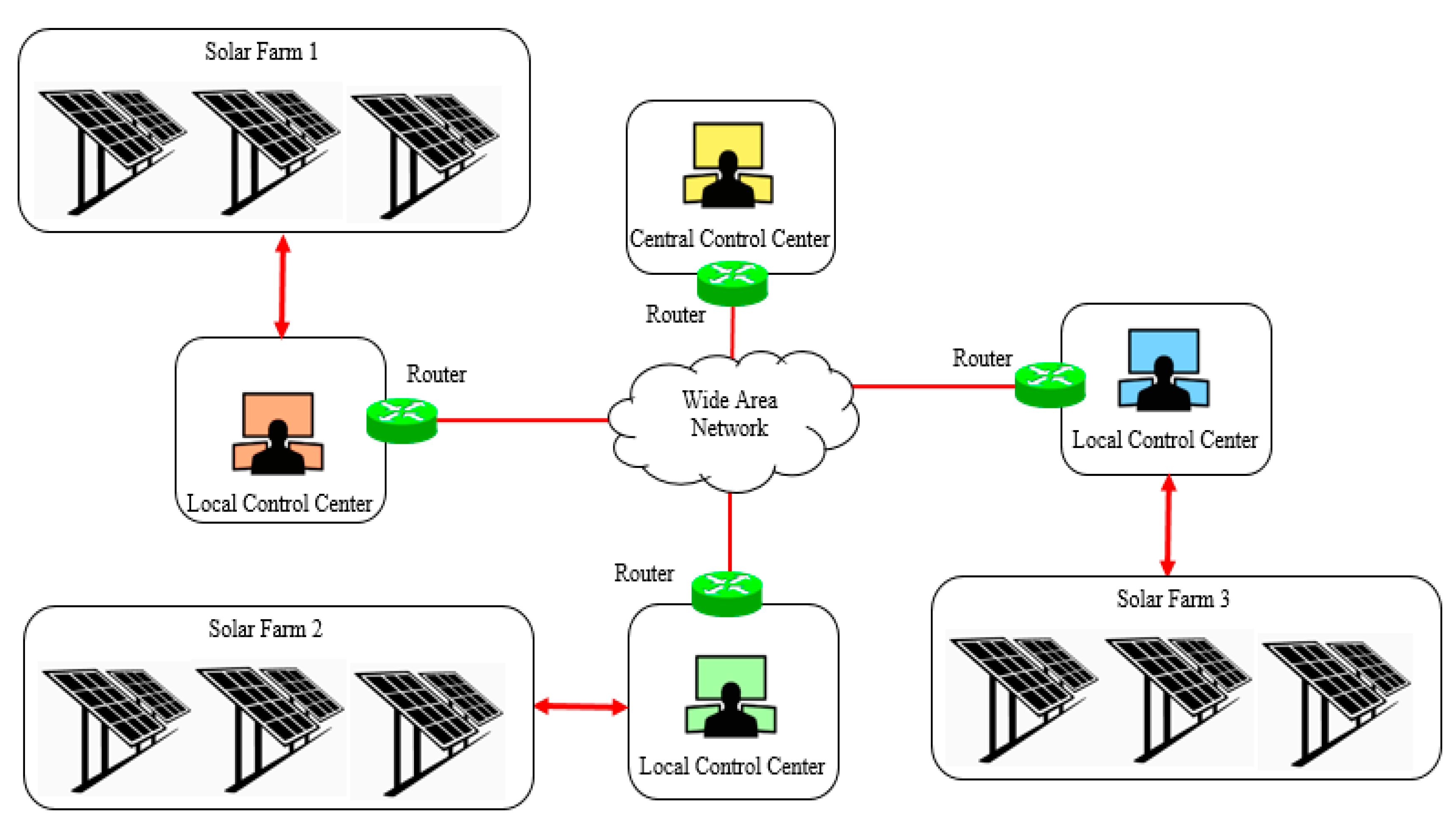
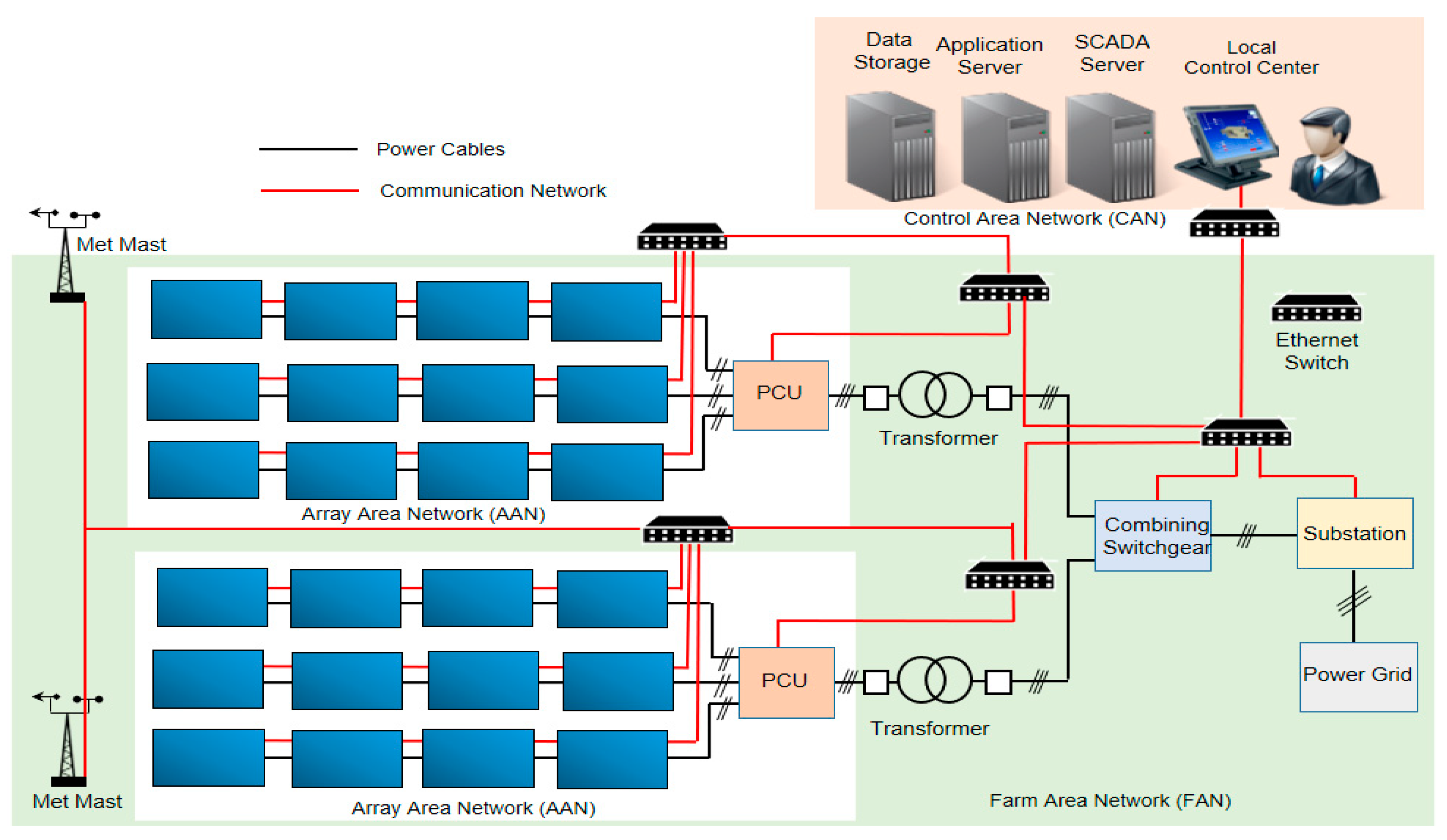
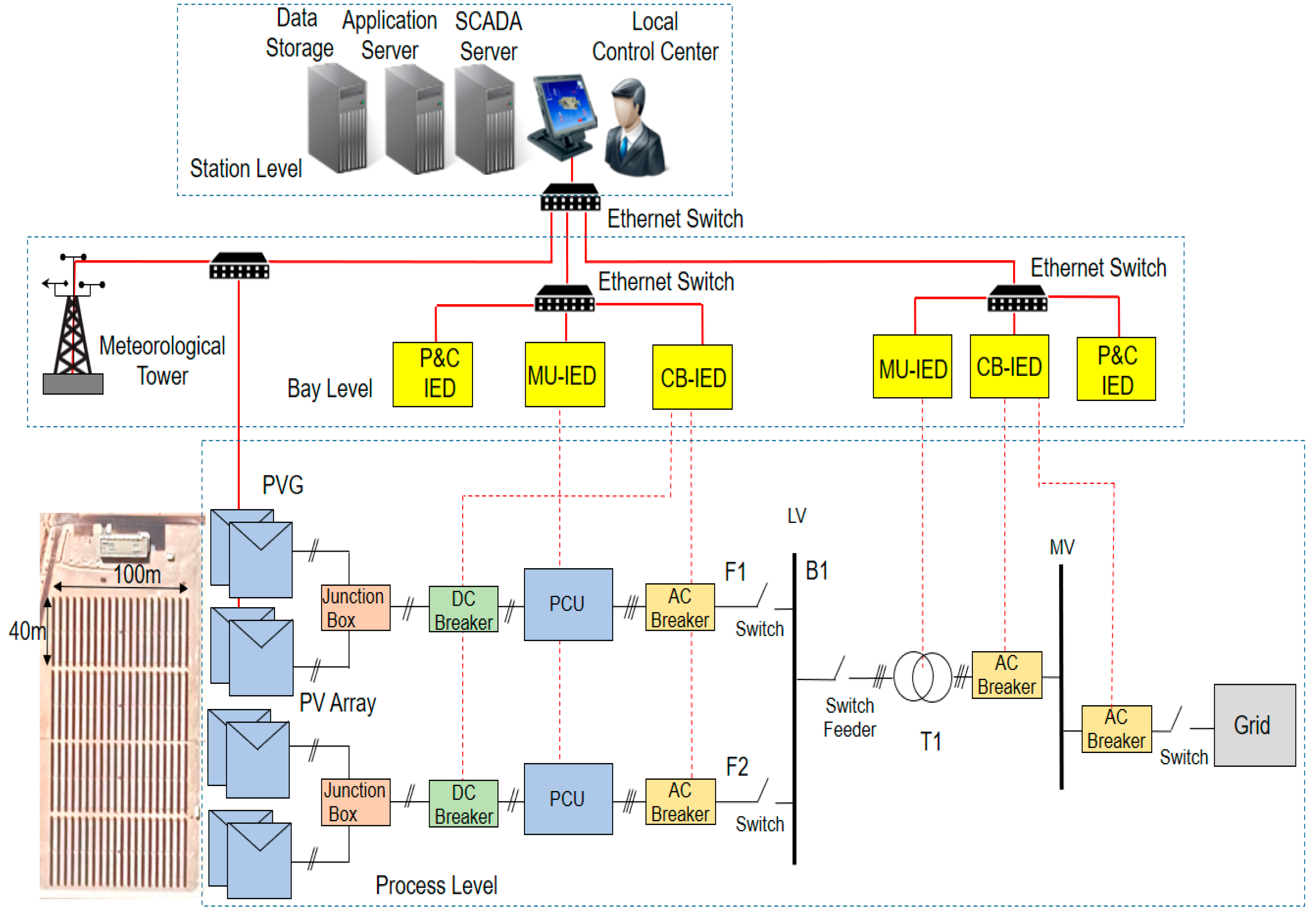
3. Communication Network Architecture for Large Scale Photovoltaic Power Plants

The proposed communication network architecture for large-scale PV power plant consists of three layers: the PV power system layer, the communication network layer and the application layer, as shown in Figure 3.

3.1. PV Power System Layer

The PV power system layer consists of all physical devices including PV modules, junction boxes, circuit breakers, protection devices, PV inverters, power cables, grid connection, transformers, the substation, etc. PV modules are connected in series to form a module string. Groups of strings are connected together in a string combined box. The string combiner boxes are connected to a power condition unit (PCU), which plays an important role in the PV power plant as it inverts the output DC voltage from PV panels to AC and is connected to a transformer based on PV power plant topology.

3.2. Communication Network Layer

The communication network layer enables two-way communications between PV power plant subsystems and the local control center. It consists of various communication devices connected with communication links. There are different types of sensor nodes and measurement devices interfacing with the power system layer. For example, pyranometers are used for measuring solar radiation, while anemometers are used for measuring wind speed and wind direction. Other measurements include modules temperature, air humidity, ambient temperature, atmospheric pressure and rain. Monitoring data from the PV subsystem and meteorological parameters are transmitted to the control center via the communication network layer. The communication network layer in PV power plant can be divided into subnetworks: the PV array area network (AAN), PV farm area network (FAN) and control area network (CAN). Each sub-network has different requirements in view of network configuration, coverage range and data rate. The main applications are given below:
  • SCADA system: Used for monitoring the performance of the PV power plant for documentation and analysis. This includes monitoring DC and AC parameters (voltage, current and power), PV modules, total generation from panels.
  • Meteorological system: Used for collecting meteorological information such as solar irradiance, ambient temperature, humidity and wind speed.
  • Protection and control system: Used for PV power plant protection. It interconnects among all protection and control IEDs in a PV power plant, which are responsible for safety and protection of the utility’s hardware components.
  • Metering the grid interface system: Used for measuring the electrical parameters at the point of interconnection. This could be done by monitoring real and reactive power, voltage and connection status at the point of interconnection in order to ensure the grid quality assurance.
The IEE 1646 Standard defines different requirements for data transmission for different applications [21]. Table 2 shows the requirements for data delivery time based on IEEE 1646 Standard. The requirements of data delivery for the protection information required strict delay compared with monitoring and control.

3.3. Application Layer

The control center is responsible for the monitoring and controlling the operation the PV power plant including PV panels, inverters, transformers, grid connection point, etc. Data collected from sensor nodes, measurement devices are processed and stored in system servers, and appropriate control actions are taken accordingly.

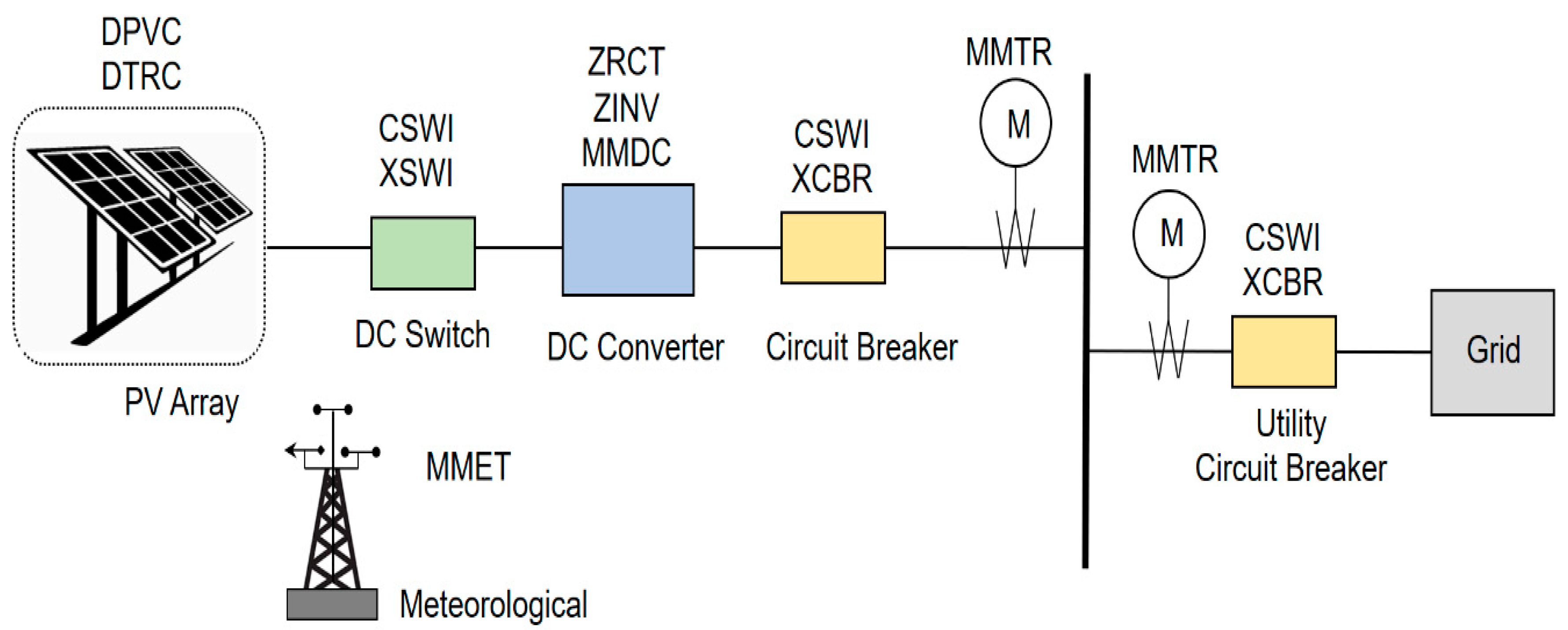
4. Modeling Photovoltaic System Based on IEC 61850-7-420 Standard

In a typical PV power plant, there are many factors that affect the plant operation, such as faults, cell damage, shading, dust, degradation, etc. [22]. Most of these factors are hidden and difficult to identify in a large-scale PV power plant. Supervisory control and data acquisition (SCADA) system represent an essential element for remote monitoring and control of PV power plant. It ensures a reliable and a safe operation for PV power plant subsystems as it enables the control center operator to analyze the performance, detect operation issues and identify faults during abnormal conditions. The PV power plant can be divided into different levels: the module level, string/array level, inverter level and grid level.
  • The module level monitors the voltages and current in each module. The status of each PV module can be determined and faults in any module can be identified.
  • The string/array level monitors the voltages and current in each string/array. Faults in any string/array can be identified.
  • The inverter level monitors the array output power and the performance of the section connected to that inverter. In the case of a malfunction, both the array and the inverter can be identified.
  • The grid level monitors the total performance of the PV power plant.
The IEC 61724 standard defines the general guideline for monitoring the overall performance of the PV system including in-plane irradiance, array output and energy storage system [23]. The required parameters to be measured are shown in Table 3, where all parameters should be continuously measured. The amount of data generated from sensor nodes are calculated based on the sampling rate, the sample size and the number of channels. The data rate was calculated given the assumption that each data sample is represented with 2 bytes (16 bit) [24].
IEC 61850-7-420 standard defines the general data model for distributed energy resource (DER) systems. The standard describes the information model of the photovoltaic system including PV panels, conversion system, circuit breakers, protection devices, and metering devices. Figure 4 shows the architecture model of the photovoltaic system based on IEC 61850-7-420 standard [25]. A photovoltaic array controller (DPVC) and a PV tracking controller (DTRC) represent the logical nodes of the PV panels, as shown in Equation (1). In order to maximize the output power of the PV system, the output voltage and current are adjusted through the maximum power point tracking.
PVLN = {DPVC, DTRC},
The main operation of the switchgear is to monitor and control the operation of circuit breakers and switches. The logical nodes of the DC switch (SWLN) is represented with a circuit breaker (CSWI) and a switch controller (XSWI) while the circuit breaker (CBLN) is represented with a circuit breaker (CSWI) and a circuit switch (XCBR), as shown in Equations (2) and (3).
SWLN = {CSWI, XSWI},
CBLN = {CSWI, XCBR},
The rectifier (ZRCT), inverter (ZINV) and DC metering (MMDC) represent the logical nodes of the inverter (INVLN), as shown Equation (4).
INVLN = {ZRCT, ZINV, MMDC},
The electric measurements are represented with the logical node metering (MMTR). The logical node MMXU represents the metering of the AC current while MMDC represents the DC current. The logical node (MMET) represent the meteorological measurements, which includes monitoring parameters of meteorological information such as solar irradiation and ambient temperature. The list of logical nodes associated with the photovoltaic system is given in Table 4.
There are three types of IED: circuit breaker CB-IED, merging unit MU-IED, and protection and control P&C IED. The CB-IED monitors the status of the circuit breaker and sends status information for the P&C IED. The MU-IED measures the current and voltage signals and transmits it to the P&C IED. The P&C IED manages and supervises the operation of all IEDs. Based on IEC 61850 standard, the P&C system can be divided into three levels: the process level, bay level and station level.

5. Network Modeling and Simulation Results

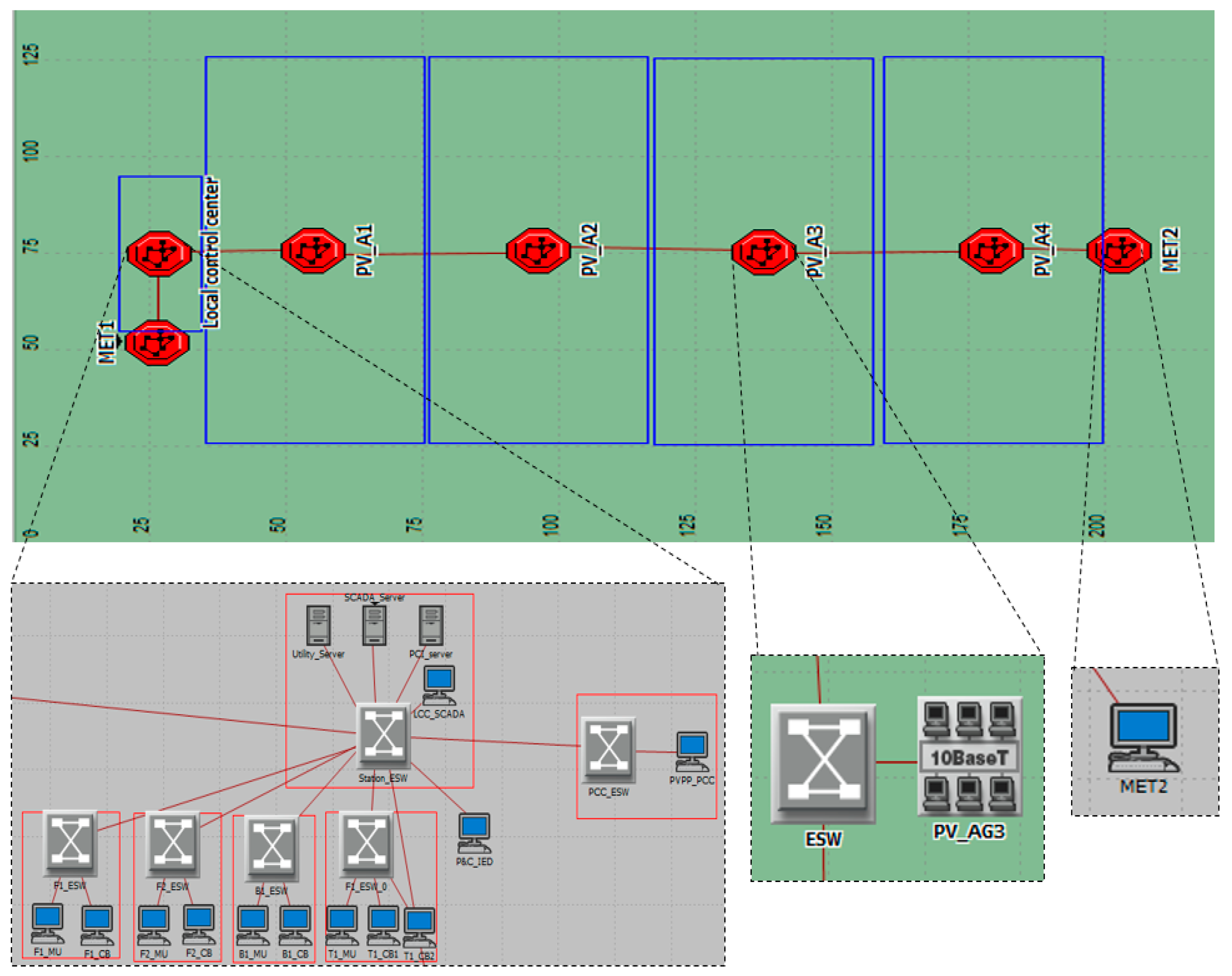
5.1. Single PV Power Plant Scenario

This section explains the simulation models that were developed to evaluate the performance of the communication network of a PV power plant. The simulation models were built using OPNET Modeler based on a real project (Layla solar plant (10 MW), phase 1) in Saudi Arabia. The developed model consists of 80 PV strings, two feeders, two power conditioning units (PCU), one bus, one transformer, two meteorological masts and a local control center, as shown in Figure 5. The main components of the PV power plant and IEDs are summarized in Table 5 and Table 6, respectively.
In a real PV power plant, independent communication networks are used to support different applications (sometimes from different service providers) where all subnetworks are connected together via a common backbone network. In this work, independent communication networks (independent communication links and switches) are considered to support different applications (PV arrays, protection and control and utility grid).
Figure 6 shows the OPNET simulation model for the PV power plant. It consists of seven octagons representing four PV arrays, two meteorological masts and one control center. The configuration is based on the actual PV power plant dimensions. Two scenarios are considered: fixed mounted PV arrays (no tracker tilt angle nor tracker azimuth angle) and PV arrays with sun trackers (each PV sun tracking unit is equipped with a pyranometer). Two different link capacities are considered for local area communication (LAN): 10 BaseT and 100 BaseT. The traffic configuration, including the source and destination, is given in Table 7. The performance of the proposed communication network is evaluated for a switched Ethernet architecture in view of bandwidth and end-to-end delay. Table 8 and Table 9 show the end-to-end delay for different scenarios of PV arrays with different channel capacities. Each PV array is modeled with an Ethernet LAN of 20 workstations in a switched topology. The results of latency are compared with different numbers of PV arrays.
In general, the architecture of the substation automation system consists of a process level, protection and control level, and station level. In this work, the substation automation system of the PV power plant is implemented using different IEDs. These different IEDs include PV generator, collector feeder, collector bus and transformer which are interconnected through a communication network. The model of the transformer IEDs consists of two CB IED, one MU IED and one P&C IED. The models of collector bus and collector feeders consist of one CB IED, one MU IED and one P&C IED. The communication network is configured as a star topology. A PCI server is used to represent the station level, while the bay level includes different protection and control IEDs. The data generated from IEDs are transmitted to the PCI server. Note that the protection and control functions require a fast response time compared with SCADA monitoring. Two scenarios are considered for the substation communication using LAN with 10 Mbps and 100 Mbps. The end-to-end delay for different protection and control IEDs are shown in Table 10.

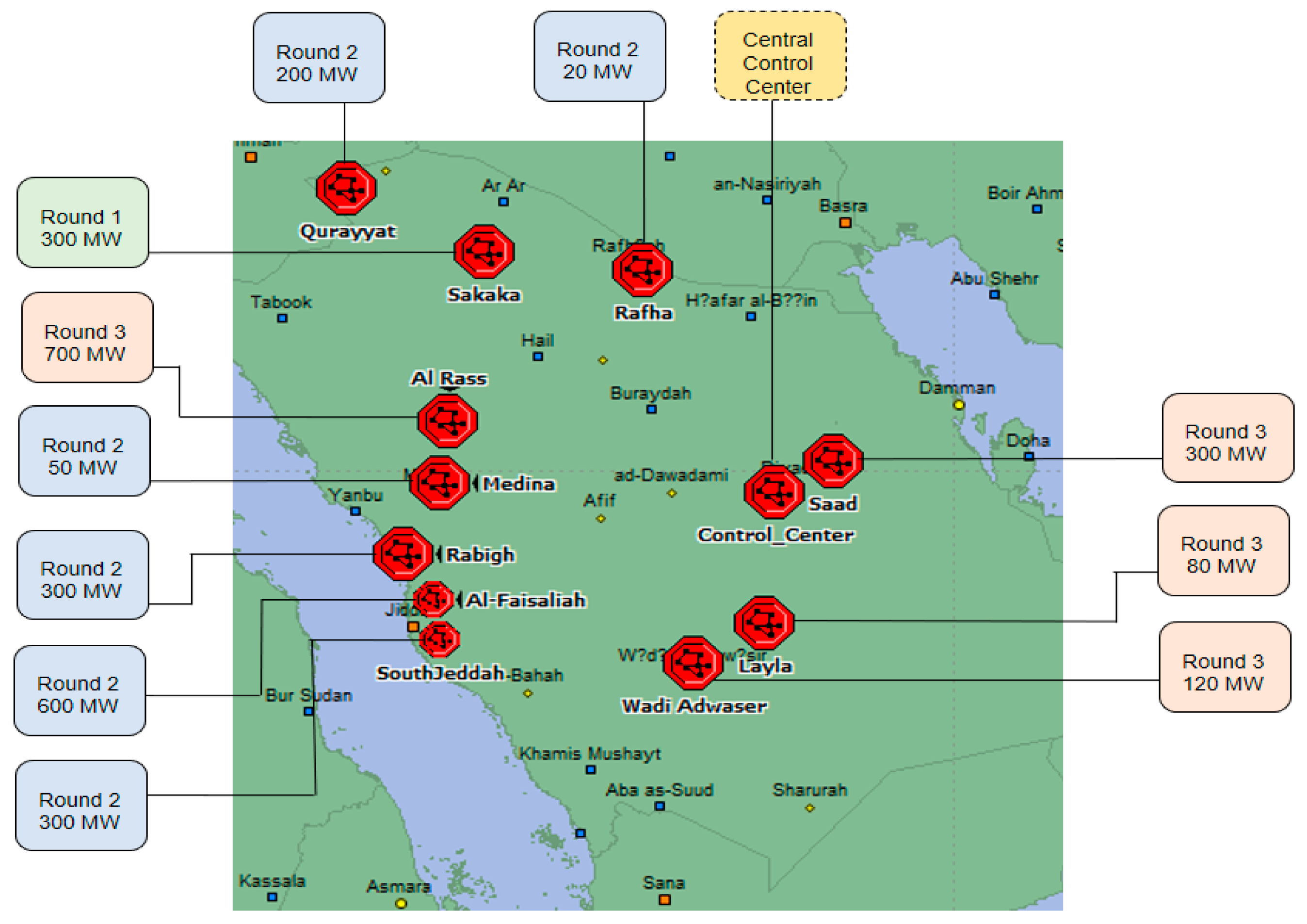
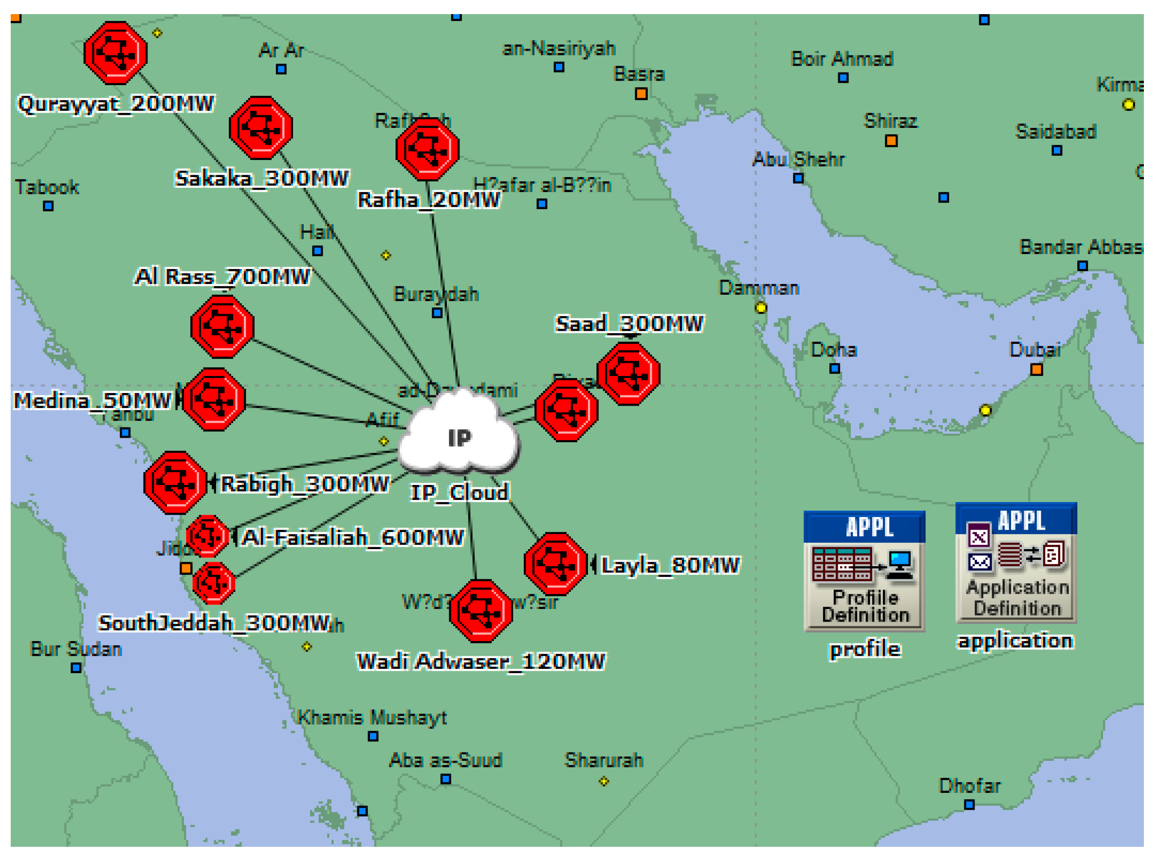
5.2. PV Power Plants Scenario

This work considers the planned PV power plants in Saudi Arabia based on the Renewable Energy Project Development Office (REPDO) [26]. Table 11 shows a list of the planned solar power projects across the kingdom. The projects have been divided into three rounds: round 1 includes one project (Sakaka PV project, 300 MW), round 2 includes six projects (1.47 GW) and round 3 includes four projects (1.2 GW). Al-Faisaliah project is the largest among them, with a generation capacity of about 600 MW. Figure 7 shows the locations of PV power plants. The solar PV power plants are distributed among different regions, where all projects will be connected to the national electricity grid.
The proposed communication network model was developed for the wide monitoring of PV power plants. It consists of 12 subnetworks (each subnetwork is represented by an octagon) and a central control center. Each PV power plant is configured to transmit the monitoring data of the point of common coupling (PCC) including voltage, current and power to the central control center (CCC), where monitoring data are stored and used by other applications such as an energy management system. As the computer systems are the core part of the control center, the system must be sized to receive, process and store the necessary information. The main elements are front-end units (industrial servers), a historian server, operator consoles, a web server and a video wall [27]. The front-end units are responsible for receiving information from PV power plants. Additional front-end units are added as the number of PV power plants increases. Historical servers are used to store the information received from the front-end units. The decision regarding the type of historical database in the control center is based on the amount of information to be stored, the scan rate and the speed required in data access using reports. The new control centers are moving toward virtual machines with the target of decreasing the amount of equipment, reducing maintenance costs, and reducing energy consumption and wiring, etc.
All PV power plants communicate with the CCC through the public communication network. Figure 8 shows the developed OPNET model for the grid integration of 11 PV power plants. The communication networks inside all subnetwork are configured as local area networks. Each subnetwork contains an Ethernet Switch, a workstation and a router. The communication among the subnetworks and the CCC is configured using the internet, which is represented by the internet protocol (IP) cloud. The communication links between each PV power plant and the IP cloud is configured with PPP-DS3 with a link capacity of 44.736 Mbps.
Considering the measured parameters at the grid side, the amount of the received traffic for voltage, current and power are 12,288, 12,288 and 10 bytes/s, respectively. The total amounts of traffic received at the control center are 270,336, 135,168 and 220 bytes/s, for current, voltage, and power, respectively. All monitoring data are received successfully.
Table 12 shows the end-to-end delay between PV power plants and the central control center using a link capacity of 44.736 Mbps. The packet discard ratio (PDR) of the IP cloud has been configured at 1%, which specifies the percentage of packets dropped (ratio of dropped packets to the total submitted packets to this cloud). In case of no PDR, the end-to-end delay was about 7.79 ms for Qurayyat PV power plant, while about 5.83 ms for Saad PV power plant. With the PDR of 1%, the end-to-end delay was about 7.93 ms for Qurayyat PV power plant, while about 5.90 ms for Saad PV power plant. The difference in end-to-end delay among different projects is due to the location of each PV power plant.

6. Conclusions

Reliable communication networks play an important role in supporting the grid integration of large scale PV power plants. The underlying communication infrastructures are responsible for real-time monitoring and have a direct impact on the performance of the PV power plants as well as the capability for meeting the target application requirements. This work proposed communication network models for the PV power system in order to evaluate future scenarios of PV power plants. Various scenarios have been considered in order to evaluate the performance of the communication network, including a single PV power plant and a group of PV power plants from different regions in Saudi Arabia. The monitoring measurements are communicated to a local control center in a single PV power plant scenario, and to a central control center in the multiple PV power plants scenario for further assessment. The proposed model considered 11 PV power plants which are geographically distributed in different regions and the proposed communication models have been evaluated with respect to end-to-end delay for different applications using OPNET Modeler. The simulation results in a single PV power plant scenario show that the maximum end-to-end delay for protection data was less than 4 ms considering a channel capacity of 100 Mbps. In the case of multiple PV power plants, the simulation results show that the background traffic and packet discard ratio have a direct impact on the end-to-end delay. Future works aim to evaluate the performance of the proposed communication network using different wireless communication technologies.

Author Contributions

Conceptualization, A.M.E., M.A.A.(Mohamed A. Ahmed) and Y.-C.K.; Methodology, A.M.E., M.A.A.(Mohamed A. Ahmed) and Y.-C.K.; Software, M.A.A.(Mohamed A. Ahmed); Validation, A.M.E., M.A.A.(Mohamed A. Ahmed), M.A.A.(Majed A. Alotaibi), A.I.A. and Y.-C.K.; Formal Analysis, A.M.E., M.A.A.(Mohamed A. Ahmed), M.A.A.(Majed A. Alotaibi), A.I.A. and Y.-C.K.; Supervision, A.M.E.; Project Administration, A.M.E.; Writing—Original Draft Preparation, A.M.E., M.A.A.(Mohamed A. Ahmed), M.A.A.(Majed A. Alotaibi), A.I.A. and Y.-C.K.; Writing—Review & Editing, A.M.E., M.A.A.(Mohamed A. Ahmed), M.A.A.(Majed A. Alotaibi), A.I.A. and Y.-C.K. All authors have read and agreed to the published version of the manuscript.

Acknowledgments

The authors acknowledge the National Plan for Sciences and Technology program (Project No. 13-ENE2210-02) by King Saud University for the financial support to carry out the research work reported in this paper.

Conflicts of Interest

The authors declare no conflict of interest.

References

  1. Salam, M.A.; Khan, S.A. Transition towards sustainable energy production—A review of the progress for solar energy in Saudi Arabia. Energy Explor. Exploit. 2018, 36, 3–27. [Google Scholar] [CrossRef]
  2. National Renewable Energy Program. Saudi Arabia Awards First NREP Solar Project. Available online: https://www.powersaudiarabia.com.sa/web/attach/news/300MW-Sakaka-Solar-PV-Project-Awarded.pdf (accessed on 10 January 2020).
  3. Yu, F.; Zhang, P.; Xiao, W.; Choudhury, P. Communication systems for grid integration of renewable energy resources. IEEE Netw. 2011, 25, 22–29. [Google Scholar] [CrossRef] [Green Version]
  4. Cabrera-Tobar, A.; Bullich-Massagué, E.; Aragüés-Peñalba, M.; Gomis-Bellmunt, O. Topologies for large scale photovoltaic power plants. Renew. Sustain. Energy Rev. 2016, 59, 309–319. [Google Scholar] [CrossRef] [Green Version]
  5. La Manna, D.; Li Vigni, V.; Riva Sanseverino, E.; Di Dio, V.; Romano, P. Reconfigurable electrical interconnection strategies for photovoltaic arrays: A review. Renew. Sustain. Energy Rev. 2014, 33, 412–426. [Google Scholar] [CrossRef]
  6. Rao, S.; Katoch, S.; Turaga, P.; Spanias, A.; Tepedelenlioglu, C.; Ayyanar, R.; Braun, H.; Lee, J.; Shanthamallu, U.; Banavar, M.; et al. A cyber-physical system approach for photovoltaic array monitoring and control. In Proceedings of the 2017 8th International Conference on Information, Intelligence, Systems & Applications (IISA), Larnaca, Cyprus, 27–30 August 2017; pp. 1–6. [Google Scholar]
  7. Paredes-Parra, J.; Mateo-Aroca, A.; Silvente-Niñirola, G.; Bueso, M.; Molina-García, Á. PV Module Monitoring System Based on Low-Cost Solutions: Wireless Raspberry Application and Assessment. Energies 2018, 11, 3051. [Google Scholar] [CrossRef] [Green Version]
  8. Paredes-Parra, J.M.; García-Sánchez, A.J.; Mateo-Aroca, A.; Molina-Garcia, A. An Alternative Internet-of-Things Solution Based on LoRa for PV Power Plants: Data Monitoring and Management. Energies 2019, 12, 881. [Google Scholar] [CrossRef] [Green Version]
  9. Guerriero, P.; D’Alessandro, V.; Petrazzuoli, L.; Vallone, G.; Daliento, S. Effective real-time performance monitoring and diagnostics of individual panels in PV plants. In Proceedings of the 2013 International Conference on Clean Electrical Power (ICCEP), Alghero, Italy, 11–13 June 2013; pp. 14–19. [Google Scholar]
  10. Pau, M.; Locci, N.; Muscas, C. A tool to define the position and the number of irradiance sensors in large PV plants. In Proceedings of the 2014 IEEE International Energy Conference (ENERGYCON), Cavtat, Croatia, 13–16 May 2014; pp. 374–379. [Google Scholar]
  11. Xu, X.; Qiao, D. Remote monitoring and control of photovoltaic system using wireless sensor network. In Proceedings of the 2011 International Conference on Electric Information and Control Engineering, Wuhan, China, 15–17 April 2011; pp. 633–638. [Google Scholar]
  12. Dhoke, A.; Sharma, R.; Saha, T.K. Condition monitoring of a large-scale PV power plant in Australia. In Proceedings of the 2016 IEEE Power and Energy Society General Meeting (PESGM), Boston, MA, USA, 17–21 July 2016; pp. 1–5. [Google Scholar]
  13. Shapsough, S.; Takrouri, M.; Dhaouadi, R.; Zualkernan, I. An MQTT-Based Scalable Architecture for Remote Monitoring and Control of Large-Scale Solar Photovoltaic Systems. In Smart Grid and Internet of Things; Pathan, A.-S.K., Fadlullah, Z.M., Guerroumi, M., Eds.; Springer International Publishing: Cham, Switzerland, 2019; pp. 57–67. ISBN 978-3-030-05928-6. [Google Scholar]
  14. Montoya, J.C.; Muñoz, C.Q.G.; Márquez, F.P.G. Remote condition monitoring for photovoltaic systems. In Non-Destructive Testing and Condition Monitoring Techniques for Renewable Energy Industrial Assets; Papaelias, M., Márquez, F.P.G., Karyotakis, A., Eds.; Elsevier: Boston, MA, USA, 2020; pp. 133–142. ISBN 978-0-08-101094-5. [Google Scholar]
  15. Zhang, J.; Hasandka, A.; Alam, S.M.S.; Elgindy, T.; Florita, A.R.; Hodge, B.-M. Analysis of Hybrid Smart Grid Communication Network Designs for Distributed Energy Resources Coordination. In Proceedings of the 2019 IEEE Power & Energy Society Innovative Smart Grid Technologies Conference (ISGT), Washington, DC, USA, 18–21 February 2019; pp. 1–5. [Google Scholar]
  16. ALI, I.; Hussain, S. Communication Design for Energy Management Automation in Microgrid. IEEE Trans. Smart Grid 2016, 9, 2055–2064. [Google Scholar] [CrossRef]
  17. Moreno-Garcia, M.I.; Palacios-Garcia, J.E.; Pallares-Lopez, V.; Santiago, I.; Gonzalez-Redondo, J.M.; Varo-Martinez, M.; Real-Calvo, J.R. Real-Time Monitoring System for a Utility-Scale Photovoltaic Power Plant. Sensors 2016, 16, 770. [Google Scholar] [CrossRef] [PubMed] [Green Version]
  18. Eltamaly, A.M.; Al-Saud, M.S.; Abokhalil, A.G. A Novel Bat Algorithm Strategy for Maximum Power Point Tracker of Photovoltaic Energy Systems under Dynamic Partial Shading. IEEE Access 2020, 8, 10048–10060. [Google Scholar] [CrossRef]
  19. Kopacz, C.; Spataru, S.; Sera, D.; Kerekes, T. Remote and centralized monitoring of PV power plants. In Proceedings of the 2014 International Conference on Optimization of Electrical and Electronic Equipment (OPTIM), Bran, Romania, 22–24 May 2014; pp. 721–728. [Google Scholar]
  20. Hongchun, Y.; Ming, X. Design of Large-Scale PV Power Station Supervisory Control and Data Acquisition System Based on Fieldbus and Industrial Ethernet; Yang, D., Ed.; Springer: Berlin/Heidelberg, Germany, 2011; pp. 351–357. ISBN 978-3-642-25992-0. [Google Scholar]
  21. IEEE Standard Communication Delivery Time Performance Requirements for Electric Power Substation Automation; IEEE Std 1646-2004; IEEE: New York, NY, USA, 2005; ISBN 978-0-7381-4503-7.
  22. Farh, H.; Othman, M.; Eltamaly, A.; Al-Saud, M. Maximum Power Extraction from a Partially Shaded PV System Using an Interleaved Boost Converter. Energies 2018, 11, 2543. [Google Scholar] [CrossRef] [Green Version]
  23. International Standard IEC 61724-1.0: Photovoltaic System Performance–Part 1: Monitoring; International Electrotechnical Commission: Geneva, Switzerland, 2017.
  24. Wei, M.; Chen, Z. Distribution system protection with communication technologies. In Proceedings of the IECON 2010-36th Annual Conference on IEEE Industrial Electronics Society, Glendale, AZ, USA, 7–10 November 2010; pp. 3328–3333. [Google Scholar]
  25. International Standard IEC 61850-7-420: Communication Networks and Systems for Power Utility Automation–Part 7-420: Basic Communication Structure–Distributed Energy Resources; International Electrotechnical Commission: Geneva, Switzerland, 2009.
  26. Saudi Arabia invites bids for Round Two of the National Renewable Energy Program. Available online: https://www.powersaudiarabia.com.sa/web/attach/news/1-august-2019.pdf/ (accessed on 1 February 2020).
  27. Gallardo-Calles, J.-M.; Colmenar-Santos, A.; Ontañon-Ruiz, J.; Castro-Gil, M. Wind control centres: State of the art. Renew. Energy 2013, 51, 93–100. [Google Scholar] [CrossRef]
Figure 1. Different configurations for PV inverter topologies. (a) Central, (b) string, (c) multi-string.
Energies 13 05527 g001
Figure 2. Communication network for a PV monitoring system.
Energies 13 05527 g002
Figure 3. Layout of grid integration of a large-scale PV power plant.
Energies 13 05527 g003
Figure 4. Logical nodes associated with photovoltaic system based on IEC 61850-7-420 standard.
Energies 13 05527 g004
Figure 5. Proposed communication network model for the PV power plant. PVG: PV generator; PCU: power conditioning unit F: feeder; B: bus; T: transformer, LV: low voltage; MV: medium voltage.
Energies 13 05527 g005
Figure 6. OPNET model for communication network of the PV power plant.
Energies 13 05527 g006
Figure 7. Geographical location of future PV power projects across Saudi Arabia.
Energies 13 05527 g007
Figure 8. OPNET simulation model for grid integration of PV power plants.
Energies 13 05527 g008
Table 1. Comparison among monitoring system used in photovoltaic (PV) power plant.
Ref.PV Monitoring SystemComments
SensorsData TransmissionStorage and Analysis
[3]NoYesNoRS-485 → Between inverter and data logger
Ethernet, WiFi, ZigBee → local monitoring
RS-232 and USB → On-site configuration
Overview of communication systems for grid integration of PV power plants
[6]NoNoYesApplication of machine learning and computer vision for improving the reliability of PV arrays
[7]YesYesNoRF data transmission between sensor nodes (for electric data and meteorological data) and the gatewayLow cost wireless monitoring system for PV module
[8]YesYesNoLong range communication using LoRa for remote monitoring of PV systems
[9]YesNoNoMonitoring system for individual panels in PV system including operating voltage and current, open circuit voltage and short circuit current
[10]YesNoNoDefine the number of irradiance sensors and the position in large PV system
[11]YesYesNoZigBee wireless network for remote condition monitoring for PV operationSensor nodes include voltage, current, irradiance and temperature
[12]NoNoYesFault detection of PV power plant including string fault, module bypassed and partial shading
[13]YesYesYesIoT-based architecture for remote monitoring of solar PV system including the backend and web server applicationMonitoring parameters include camera, voltage, current, irradiance and temperature
[14]NoNoYesThe PV monitoring system includes an algorithm with a thermal camera for hot spot detection
[15]NoYesNoDifferent communication technologies including Ethernet, WiFi, WiMAXSimulation of hybrid communication models for rooftop solar PV panels
Table 2. Requirements for data delivery time based on IEEE 1646 Standard [21].
Information TypeInternal to SubstationExternal to Substations
Protection4 ms8–12 ms
Monitoring and control16 ms1 s
Operation and Maintenance1 s10 s
Image Files10 s60 s
Audio and Video1 s1 s
Table 3. Measured parameters for the photovoltaic system based on IEC 61724 standard.
LevelParametersSymbolUnitSampling RateChannel NumberData Rate
PV ArrayOutput voltageVAV360 Hz1720 bytes/s
Output currentIAA360 Hz1720 bytes/s
Output powerPAkW5 Hz110 bytes/s
Module temperatureTm°C1 Hz12 bytes/s
Tracker tilt angleØTdegree3 Hz16 bytes/s
Tracker azimuth angleØAdegree3 Hz16 bytes/s
Utility GridUtility voltageVUV2048 Hz312,288 bytes/s
Current to utility gridITUA2048 Hz312,288 bytes/s
Current from utility gridIFUA2048 Hz312,288 bytes/s
Power to utility gridPTUkW5 Hz110 bytes/s
Power from utility gridPFUkW5 Hz110 bytes/s
Meteoro-logicalTotal irradianceGIWm−2100 Hz1200 bytes/s
Ambient air temperatureTam°C1 Hz12 bytes/s
Wind speedSwm/s3 Hz16 bytes/s
Wind DirectionDwdegree3 Hz16 bytes/s
Table 4. List of logical nodes associated with photovoltaic system based on IEC 61850-7-420.
NameLogical NodeDescription
Photovoltaic ArrayDPVCPhotovoltaic array controller
DTRCPhotovoltaic Tracking controller
DC SwitchCSWISwitch Controller
XSWICircuit Switch
DC ConverterZRCTRectifier
ZINVInverter
MMDCDC Measurement
Circuit BreakerCSWISwitch Controller
XCBRCircuit Breaker
MeteringMMTRMetering
Meteorological TowerMMETMeteorological Information
Table 5. Summary of the system components for the developed model of the PV power plant.
ComponentsNumberComments
PV Strings80Every string consist of 20 modules
DC Box8Every 10 strings are connected to one DC box
PCU2Every 4 boxes are connected to one PCU
Transformer1Every PCU is connected to one transformer
Table 6. Intelligent electric device (IED) configurations for the developed model of the PV power plant.
ComponentsCB IEDMU IEDP&C IED
Transformer (T1)211
Collector Bus (B1)111
Collector Feeder (F1 and F2)111
PV generator (PVG)111
Table 7. Traffic configuration of the PV power plant.
Traffic TypeSourceDestination
Photovoltaic ArrayPV_A1, PV_A2, PV_A3, PV_A4SCADA Server
MeteorologicalMET1, MET2SCADA Server
ProtectionFeeder, bus and transformer (MU IED, CB IED)PCI Server
Utility GridPVPP_PCCUtility Server
Table 8. Internet Protocol (IP) end-to-end delay (ms) for fixed mounted PV arrays (without sun trackers) with different link capacity.
Scenario10 Mbps100 Mbps
Array 1Array 2Array 3Array 4Array 1Array 2Array 3Array 4
1 PV Array0.501---0.053---
2 PV Arrays0.4930.624--0.0530.066--
3 PV Arrays0.5180.6980.825-0.0540.0660.079-
4 PV Arrays0.5750.6970.8180.9090.0530.0670.0810.092
Table 9. IP end-to-end delay (ms) for PV arrays (with sun trackers) with different link capacity.
Scenario10 Mbps100 Mbps
Array 1Array 2Array 3Array 4Array 1Array 2Array 3Array 4
1 PV Array0.423---0.046---
2 PV Arrays0.4580.558--0.0470.058--
3 PV Arrays0.4940.5630.703-0.0470.0580.070-
4 PV Arrays0.4710.6600.7440.9300.0470.0590.0690.081
Table 10. End-to-end delay for different protection IEDs.
Dedicated NetworkShared Network
10 Mbps100 Mbps10 Mbps100 Mbps
F1-MU
F1-CB
22.65 ms
4.34 ms
2.26 ms
0.44 ms
25.82 ms
4.79 ms
2.31 ms
0.54 ms
F2-MU
F2-CB
22.40 ms
4.31 ms
2.24 ms
0.42 ms
25.31 ms
4.61 ms
2.27 ms
0.47 ms
B1-MU
B1-CB
22.30 ms
4.09 ms
2.22 ms
0.40 ms
24.92 ms
4.21 ms
2.25 ms
0.45 ms
T1-MU
T1-CB1
T1-CB2
22.93 ms
2.97 ms
4.78 ms
2.29 ms
0.28 ms
0.47 ms
26.09 ms
3.34 ms
4.61 ms
2.33 ms
0.34 ms
0.52 ms
Table 11. Summary of future PV power projects in Saudi Arabia [20].
RoundStatusSolar PV ProjectsCapacity (MW)Region
Round 1
300 MW
OperatingSakaka Project300Al Jouf
Round 2
1470 MW
Pre-DevelopedQurayyat Project200Al Jouf
Rabigh Project300Mecca
South Jeddah Project300Mecca
Al-Faisaliah Project600Mecca
Rafha Project20Northern Borders
Madinah50Medina
Round 3
1200 MW
Pre-DevelopedLayla Project80Riyadh
Wadi Al Dawaser Project120Riyadh
Saad Project300Riyadh
Al Rass Project700Riyadh
Table 12. End-to-end delay between PV power plant and the central control center. PDR: packet discard ratio.
LCCLink Capacity (DS3)
No PDRPDR (1 %)Background Traffic (50 %)
Sakaka Project7.50 ms7.67 ms8.06 ms
Qurayyat Project7.79 ms7.93 ms8.21 ms
Rabigh Project6.97 ms7.19 ms7.43 ms
South Jeddah Project7.22 ms7.28 ms7.59 ms
Al-Faisaliah Project6.38 ms6.48 ms6.93 ms
Rafha Project7.73 ms8.01 ms8.31 ms
Madina Project6.32 ms6.67 ms7.16 ms
Layla Project6.08 ms6.17 ms6.51 ms
Wadi adwaser Project7.441 ms7.448 ms7.99 ms
Saad Project5.83 ms5.90 ms6.37 ms
Al Rass Project6.73 ms6.94 ms7.42 ms
Publisher’s Note: MDPI stays neutral with regard to jurisdictional claims in published maps and institutional affiliations.

