Article

Thermal Efficiency of Oxyhydrogen Gas Burner

by
Roberto Moreno-Soriano
1,2,
Froylan Soriano-Moranchel
1,
Luis Armando Flores-Herrera
1,
Juan Manuel Sandoval-Pineda
1,* and
Rosa de Guadalupe González-Huerta
2,*
1
Instituto Politécnico Nacional, Sección de Estudios de Posgrado e Investigación, ESIME-U. Azc., Av. de las Granjas 682, Col. Santa Catarina, Ciudad de México CP 02250, Mexico
2
Instituto Politécnico Nacional, ESIQIE, Laboratorio de Electroquímica, UPALM, Ciudad de México CP 07738, Mexico
*
Authors to whom correspondence should be addressed.
Energies 2020, 13(20), 5526; https://doi.org/10.3390/en13205526
Submission received: 21 September 2020 / Revised: 13 October 2020 / Accepted: 16 October 2020 / Published: 21 October 2020
(This article belongs to the Section A5: Hydrogen Energy)

Abstract

:
One of the main methods used to generate thermal energy is the combustion process. Burners are used in both industrial and residential applications of the open combustion process. The use of fuels that reduce polluting gas emissions and costs in industrial and residential processes is currently a topic of significant interest. Hydrogen is considered an attractive fuel for application in combustion systems due to its high energy density, wide flammability range, and only produces water vapor as waste. Compared to research conducted regarding hydrocarbon combustion, studies on hydrogen burners have been limited. This paper presents the design and evaluation of an oxyhydrogen gas burner for the atmospheric combustion process. The gas is generated in situ with an alkaline electrolyzer with a production rate of up to 3 sL min−1. The thermal efficiency of a gas burner is defined as the percentage of the input thermal energy transferred to the desired load with respect to a given time interval. The experimental results show a thermal efficiency of 30% for a minimum flow rate of 1.5 sL min−1 and 76% for a flow rate of 3.5 sL min−1. These results relate to a 10 mm height between the burner surface and heated container.

1. Introduction

New environmental regulations for the generation of thermal energy with stationary systems have motivated the development of burners that use clean fuel. Hydrogen is considered a clean fuel under the electric industry law of the Mexican regulations issued in 2014 [1]. Two methods for hydrogen usage prevail: first, as the feed to fuel cells for electricity generation or, second, through a combustion process to generate heat. Worldwide efforts have been made to commercialize the proton exchange membrane fuel cell (PEMFC) in recent years; however, the cost of PEMFC is still considerably higher than that of conventional combustion devices (burners and internal combustion engines). Therefore, in the short term, hydrogen as a fuel will be implemented using the existing infrastructure, rendering the necessary changes and adaptations simple and inexpensive. This will facilitate the implementation of rules and regulations of hydrogen uses so that after a decade, the PEMFC could be used extensively [2,3].
In an atmospheric combustion process, hydrogen can be used alone or, in appropriate proportions, as a partial complementary substitute for natural gas (NG) or liquefied petroleum gas (LPG). When considering fuels with a high hydrogen content (>60%), factors such as the combustion velocity, temperature, and flashback or blow-off flame should be controlled with an appropriate burner design. Therefore, burners with a complex flow rate regime have been proposed, such as swirl burners, flat flame burners, micro-mix burners, and partial-premixed body burners. These devices operate with a highly optimized flow rate to achieve an efficient performance while ensuring minimal production of contaminants [2]. The lower calorific value of hydrogen is 122 kJ/g which is higher than that of other hydrocarbon fuels, such as gasoline with 45 kJ/g and NG with 42 kJ/g. Safety standards must be strictly adhered to when handling hydrogen, which has a safety factor equal to 1 compared with 0.8 and 0.53 for that of methane and gasoline, respectively. In contrast with methane and gasoline, hydrogen has a very low density, high diffusion coefficient, wider ignition limits, and higher ignition temperature. The full benefits of hydrogen as a clean, versatile, and efficient fuel will depend on the raw materials and processes used in its production [2,3,4,5,6]. Hydrogen can be produced from various renewable and non-renewable resources; currently, its production is based mainly on fossil fuel to the steam reforming process (96%). Electrolysis technology is used to produce the remaining 4%; however, energy is required to split the molecules. If electric current is produced by a renewable source (e.g., solar PV or a wind turbine), the clean hydrogen produced is known as green hydrogen; the objective is to eliminate fossil fuels from the water-splitting cycle. A water alkaline electrolyzer (WAE) utilizes a hydroxyl ions (OH) solution, whereby the water molecule is separated into hydrogen and oxygen when direct current electrical energy is applied. This technology is prominent among others such as the proton exchange membrane electrolyzer (PEME) since it has the greatest maturity and many devices that offer the advantage of low cost and simplicity are commercially available [3,4]. In a WAE, hydrogen and oxygen can be produced separately if a membrane is used between the electrodes. Gases of 99.9% purity can be obtained in a water alkaline electrolyzer (WAE) with a basic purification system, which is suitable for combustion systems. The mixture of hydrogen and oxygen (2H2/O2) produced in stoichiometric proportions in the WAE without a membrane is known by various names, such as hydroxy gas, oxyhydrogen gas, and Brown gas; oxyhydrogen gas (OH2G) is used in this study. The first use of this gas was reported by Brown for welding processes. In recent years, OH2G has been used mainly as a supplement to fuels for internal combustion engines due to its excellent combustion properties. Most of the research studies conducted in the field of diesel and gasoline vehicle engines with OH2G dual-combustion resulted in lower fuel consumption, increased engine performance, and reduced emissions of polluting gases [5,6,7]. The H2OG should not be stored for safety reasons, its use is based on avoiding heavy and complex hydrogen storage systems, it should be produced in situ, using an alkaline electrolyzer, improving safety and eliminating storage systems. In addition, hydrogen can be used in some of the existing equipment and infrastructures designed for NG applications; several studies have shown that NG can be mixed with hydrogen as a fuel [8,9,10,11,12,13]. In the same way, OH2G can be used as a fuel in industrial and domestic applications, such as cutting and welding processes, domestic heating, or cooking. Uykur et al. [12] evaluated the addition of H2 (10–20%) and OH2G (10%) to methane. The results show that the addition of 10–20% H2 increases the flame combustion rate (SL) by 8–15%. Echeverri et al. [13] performed a numerical and experimental analysis of OH2G addition in laminar flames premixed with methane/air, obtaining a maximum increment of 14.8% in the rate of combustion with 25% OH2G in the gas mixture. Pan et al. [14] investigated the efficiency of a porous media micro combustor with numerical analysis. They considered OH2G mixtures, the equivalence ratio (∅), and the flow rate in the gas mixture. The results show enhanced efficiency for micro combustion with ∅ = 0.8 and a flow rate of 6 m s−1. Tanneberger et al. [15] analyzed the efficiency of the combustion of OH2G under stoichiometric conditions by applying the concept of dilute (or wet) combustion with steam to reduce NOx and CO emissions. The results revealed: for temperatures above 826.85 °C, the combustion efficiency exceeds 95%, while at lower temperatures the efficiency decreases significantly [16].
This paper presents the design and evaluation of OH2G burners, where the OH2G is produced in situ using a WAE. The design analysis allows us to determine the optimal configuration (diameter, length, spacing, and number) of the flame ports in the burner, thus guaranteeing adequate combustion while simultaneously avoiding backlash or blow-off flame. Thermal evaluation of the flame generated allows us to quantify the efficiency of the OH2G burner; the relation between flame stability and gas flow rate produced in the WAE is obtained. The results provide an improved perspective on the advantages of using OH2G as the fuel gas, which can be used alone or in parallel with NG or LPG burners. Moreover, its implementation is simple and cheap, without the need for radical modifications to facilities.

2. Materials and Methods

Burners used in domestic appliances are of the Bunsen type and are commonly referred to as atmospheric burners and consume commercial hydrocarbon gas (LPG or NG) as fuels. The materials used for these burners are carbon steel, stainless steel, copper, and brass, so its costs are accessible. Atmospheric burners need a portion of the air to be mixed with the gas before it reaches the burner ports; this is called primary air. The additional air required is taken from the atmosphere surrounding the flames and is termed secondary air. The primary air is the most important; if the volume is increased, a limit is established above which the flames either blow away from the ports or flashback into the burner, depending upon the gas rate used. Furthermore, the volume of the primary air decreases to a limit below which the combustion process is incomplete [16].
For OH2G burners, the operation principle and materials used for their manufacture are the same as the burners for NG and LPG. In this case, the stoichiometric amount of oxygen or primary air is already mixed with the fuel; therefore, the combustion process will depend only on the flow rate of oxyhydrogen gas (OH2G) produced in the WAE.
The burner design is influenced by the type of fuel. Burner design analysis allows for the selection of a burner that delivers the most satisfactory performance, which includes an efficient combustion process, high heat transfer, and operational safety. One of the principal requisites of a well-designed burner is its capability to completely burn the gas supplied to it. The oxidizer-fuel rates can be used to adjust the design of the burner components (injector, throat, and head). Chemically, the complete combustion of oxyhydrogen is defined as (1):
2 H 2 + O 2 2 H 2 O
The equivalence ratio (∅) given in Equation (2), is used to identify the quality and type of mixture (fuel/oxidizer) according to the flow rate characteristics of each gas:
= R a c t R s t o i = ( m ˙ H 2 m ˙ O 2 ) a c t / ( m ˙ H 2 m ˙ O 2 ) s t o i
where Ract represents the fuel/oxidizer ratio according to the gases supplied and Rstoi represents the stoichiometric ratio to guarantee combustion of the gas mixture. m ˙ H 2 is the mass flow rate of hydrogen and m ˙ O 2 is the mass flow rate of oxygen. ∅ = 1 represents a mixture under stoichiometric conditions, ∅ < 1 represents a mixture with excess oxidizer, and ∅ > 1 represents a mixture with excess fuel [14].

2.1. H2 and OH2G Gas Properties

Hydrogen is a colorless and odorless gas with a molar mass of 2.02 g mol−1, a density of 0.089 g L−1 (at 25 °C and 1 atm), and higher and lower heat values of 142.18 kJ g−1 and 120.21 kJ g−1, respectively.
The properties of OH2G at 25 °C are as follows: molar mass of 12.01 g mol−1, a density of 0.49115 g L−1, a volumetric ratio of 2:1 of H2 (66.6%) and O2 (33.34%), and upper and lower calorific values of 12,751 kJ m−3 (142.18 kJ g−1) and 10,789 kJ m−3 (120.21 kJ g−1), respectively, which coincide with the values for pure hydrogen. The temperature of the adiabatic flame is 2107 °C and 2800 °C for hydrogen mixtures with air and oxygen, respectively [17,18].
The homemade water alkaline electrolyzer (WAE) is a dry cell system without a membrane between the electrodes, which has a common outlet for oxygen and hydrogen gases (oxyhydrogen gas), the ten electrodes are nickel-based, the connection is serial; PDM gaskets and alkali solution (NaOH, 5 wt%) were used. Its operation ranges are powered from 100 W–800 W and temperatures from 30 °C to 80 °C. A WAE was chosen because the device is one of the easiest ways for oxyhydrogen production, offering the advantage of simplicity and lower costs. In this study, the OH2G production system does not have the ability to compress the generated gas, and the system pressure is low at 1 atm. For this reason, the flow, pressure, composition, and temperature of OH2G at the burner inlet will depend directly on the operating conditions of the WAE, which include the operating power, electrolyte concentration, operating temperature, and time of WAE operation.

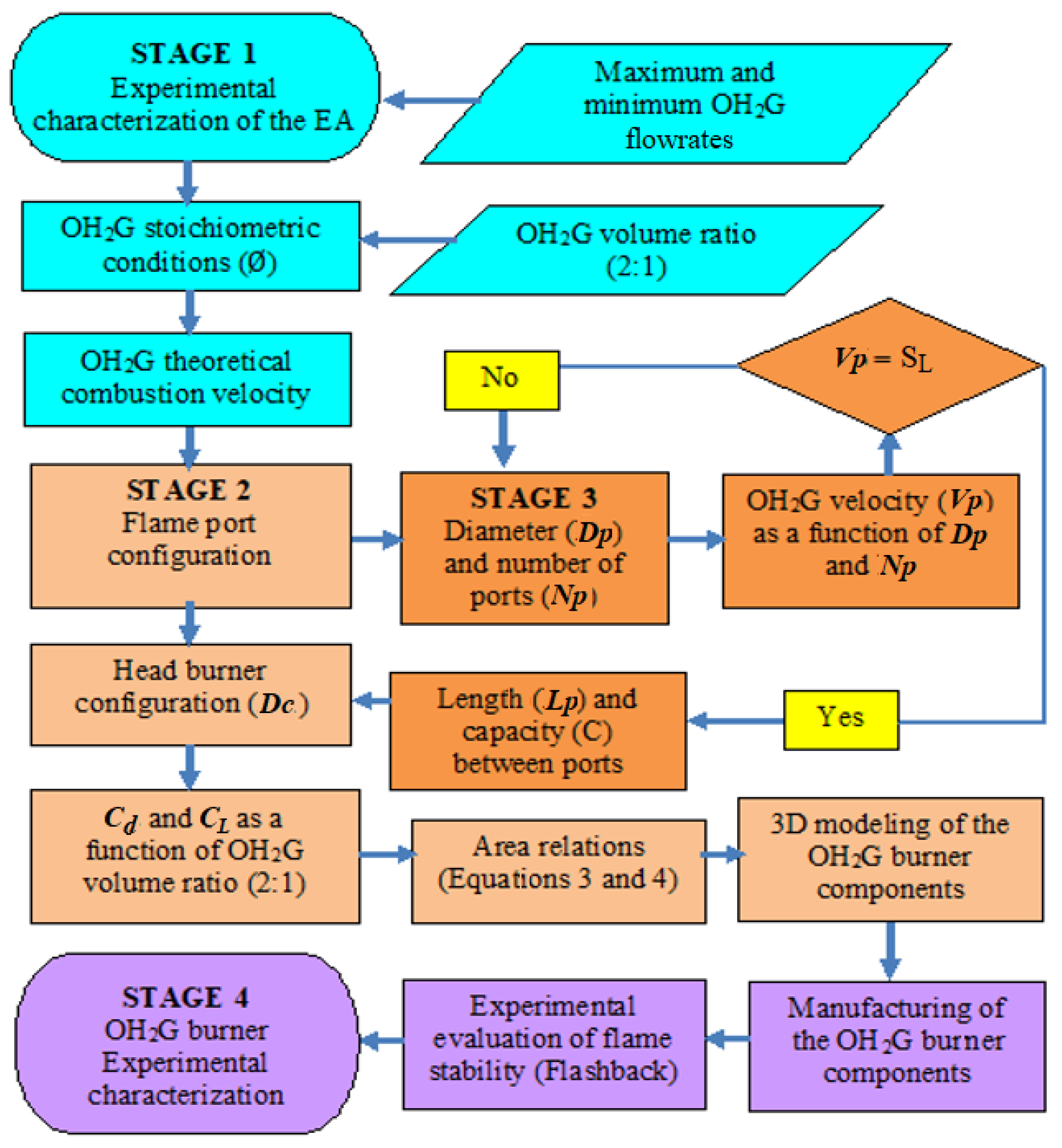
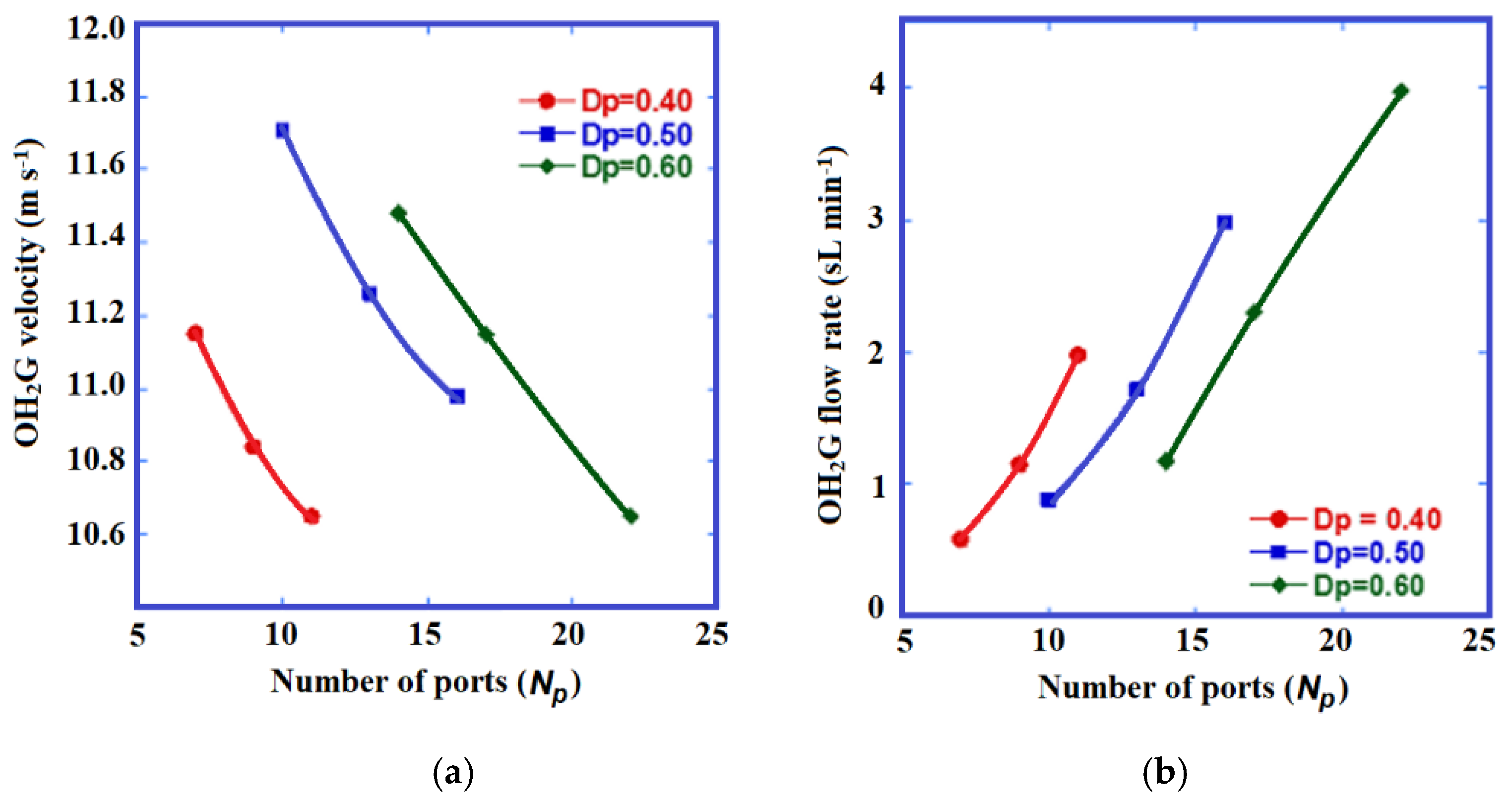
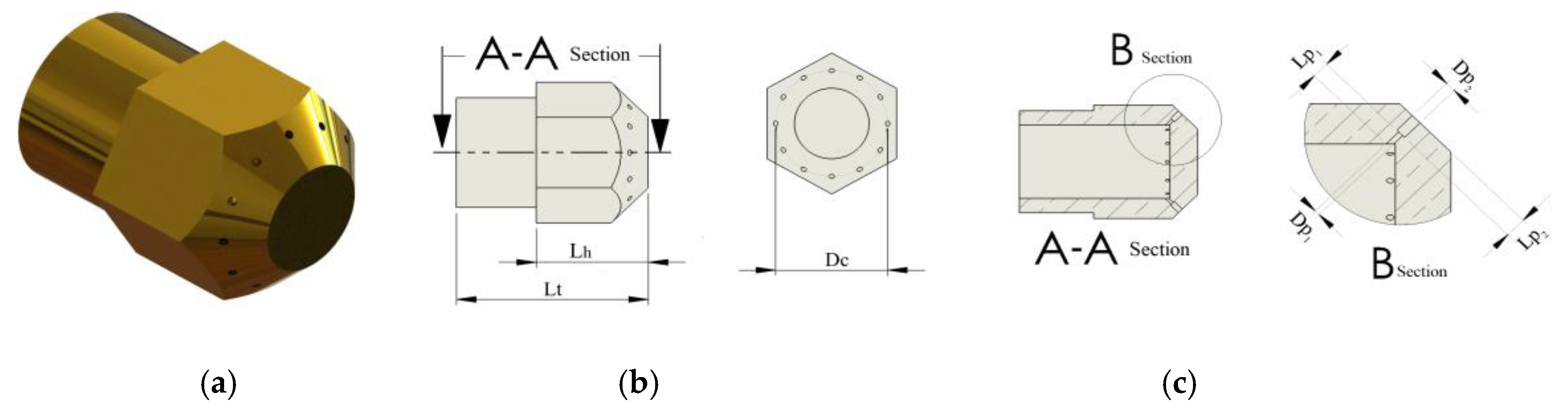
2.2. Procedure to Establish Dimensions of the Burner

The area relationships, presented by Jones et al. [19], were used to establish the dimensions of the main sections of the burner and to calculate the optimal ratio between the injector area (Ai) and the throat area (At), Equation (3):
A i A t = σ ( σ + R ) ( 1 + R ) ( 1 + C L )
in which, σ is the relative density of the gas mixture and R is the (air/fuel) drag ratio. Jones also calculated the relationship between the throat area (At) and the total area of the flame portholes (Ap), using Equation (4):
A t A P = C d 1 + C L
where CL and Cd are the friction loss coefficients generated in the gas as it flows through the burner sections. They have typical values between 30% and 60% considering a primary air composition (the portion of air required to complete combustion mixes with the gas before it reaches the burner port), OH2G has a 66.6–33.4% volumetric relationship in the fuel-oxidant premixing stage. At the top of the burner, the number of flame ports (Np) is defined as Equation (5) [19,20,21]:
N p = m ˙ m i x ρ m i x A P V p
To characterize the combustion requirements, the flame port design is optimized to define the gas flow rate characteristics before ignition. Important changes are observed if the geometry (Ap), flow rate ( m ˙ m i x ) , density ( ρ m i x ) , and gas velocity in the flame port (Vp) (without combustion) are modified as demonstrated in the continuity Equation (6) [21,22,23]:
V p = m ˙ m i x A P ρ m i x
Compared to research conducted with regard to hydrocarbon gas flame ports, limited studies have been performed on hydrogen or OH2G. Jones et al. [19] recommended a maximum spacing between ports of 6 mm, a depth/diameter ratio greater than two, a length in the mixing zone of 10 to 12 times the throat diameter (Dt), and a Dp = 0.80 mm for hydrogen/air mixtures. OH2G is produced under stoichiometric conditions (∅ = 1); thus, the risk of flashback increases. This is attributed to the difference between the gas velocity (Vp) and the combustion rate (SL) in the flame ports. In this case, Vp depends directly on the configuration of the flame port and SL is a function of the equivalence ratio (∅) in the gas mixture, where the value of SL can be established to be within a range of 9.5–10.30 m s−1 according to studies on H2/O2 stoichiometric conditions [24,25,26,27,28,29]. Figure 1 describes the method used for the development of the OH2G burner.
Figure 2 show the evaluation of the number of flame ports with respect to the OH2G flow rate from 0.5 to 4 sL min−1 (sL means liters to standard conditions at 25 °C and 1 atm) this flow was measured with the flow meter Alicat Scientific (which is special for oxyhydrogen flow and operating range of 0-20 L min−1) and gas velocities in the flame port (Vp) were calculated for port diameters (Dp) of 0.40, 0.50, and 0.60 mm. Figure 2a shows the relationship between the OH2G velocity (m s−1) and the number of ports. In this case, Dp is defined and the OH2G flow rate for each flame port is evaluated. The results correspond to Vp values higher than those found in the literature for a combustion velocity of 9.50–10.30 m s−1 to guarantee the stability of the flames at each port.
Figure 2b shows the OH2G flow rate (sL min−1) according to the diameter and number of defined ports. The OH2G flow rate represents the minimum flow rate required to guarantee that the developed velocity (Vp) of OH2G in each of the flame ports is greater than or equal to the OH2G combustion rate (SL), to prevent the development of flashback in the generated flames.
The dimensions of the different burner sections are obtained from the optimization of the configuration of the flame ports. Figure 3a shows the final design of the burner head, Figure 3b describes the distribution of flame ports where A-A is a cross section, Lh is the head length, Lt is the burner length total and Dc is a center diameter; and Figure 3c shows the cross section B, where are showed Dp and Lp configuration of the flame ports in the burner head, a port diameter (Dp1) of 0.50 mm and to a and length (Lp1) of 1.60 mm in order to accelerate the flow to a velocity of 11.7 m s−1 are selected for a total of 12 flame ports distributed in the burner head with a spacing of 3 mm between ports, and (Dp2) of a 1.5 mm and (Lp2) of a 2 mm to direct the flow into the burner head, improving stability of the flame.

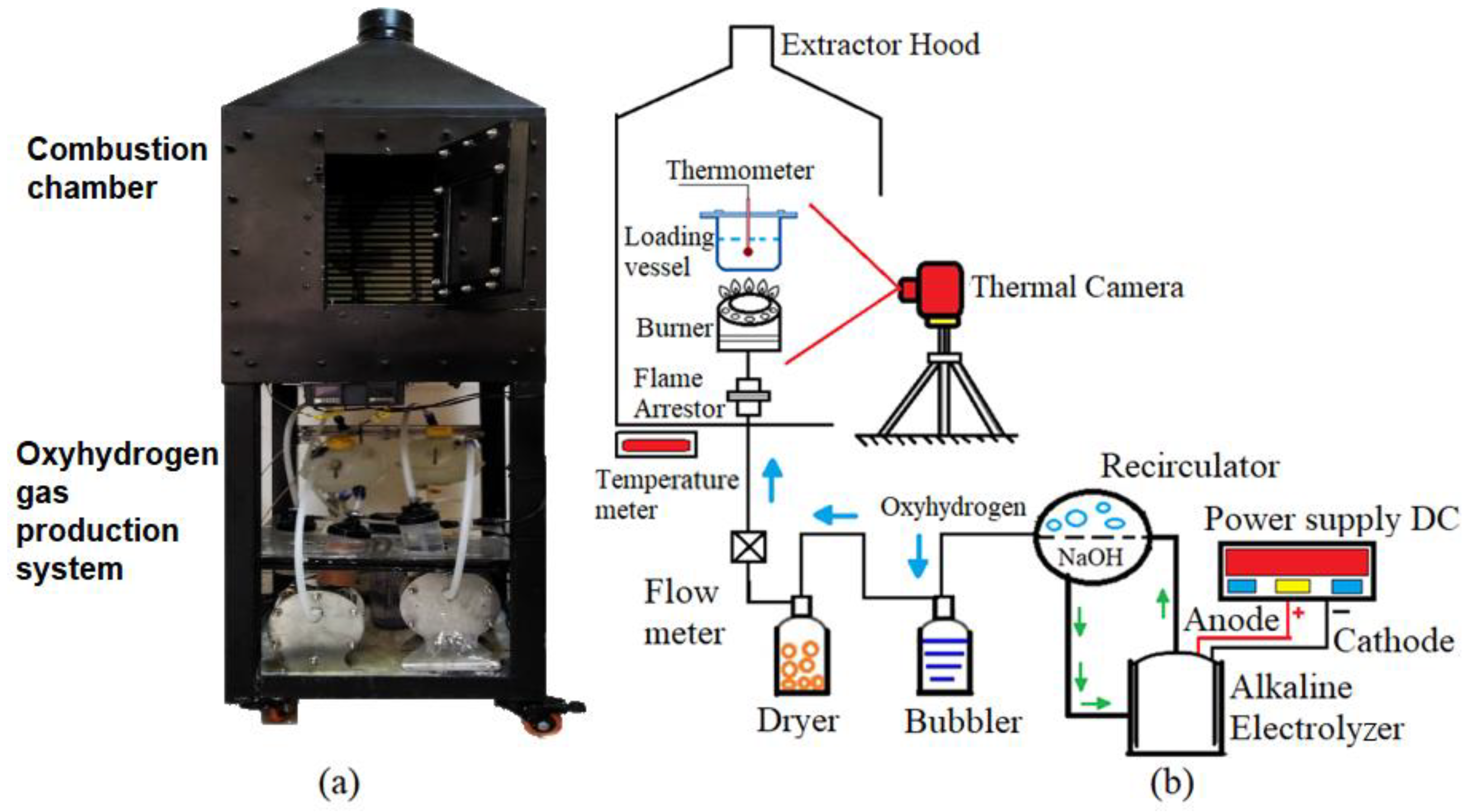
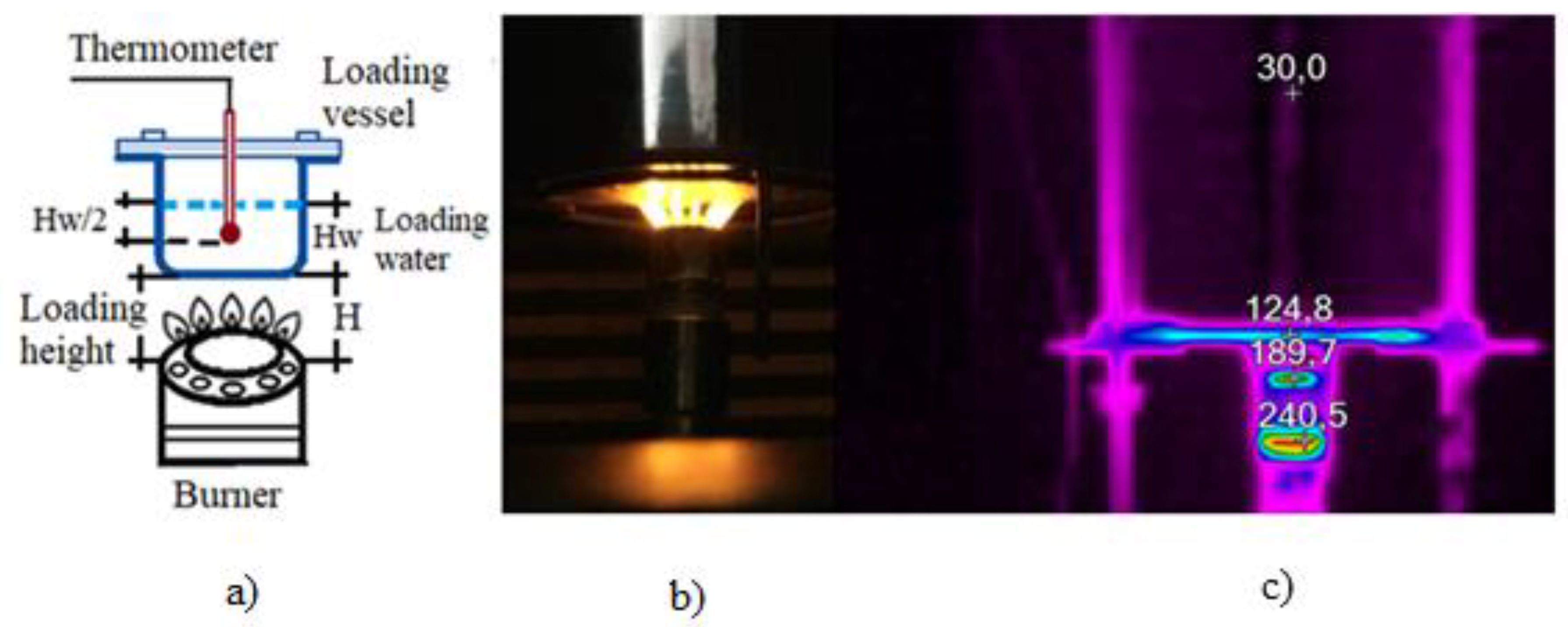
2.3. Burner Evaluation in the Experimental Test Module

The thermal efficiency of the burner (q) depends on the mass flow rate m ˙ O H 2 G and Lower Calorific Value (LCV) of OH2G, as described in Equation (7):
q = m ˙ O H 2 G L C V O H 2 G
The thermal efficiency of a gas burner is defined as the percentage of the input thermal energy transferred to the desired load with respect to a time interval. In this case, the thermal efficiency is determined by measuring the required time to produce an increment of 50 °C from the initial temperature for a standard load of 1 kg of water as described in Equation (8):
η = ( m w C p w + m R C p R ) ( T 2 T 1 ) m ˙ O H 2 G L C V O H 2 G
where mw and mR are water and container masses, respectively. Cpw and CpR correspond to the water and container-specific heats, respectively, T1 is the initial room temperature in the place of the experiment, and T2 is the final temperature of the water load, both temperatures were measured with a thermometer. Figure 4 shows the experimental test module (ETM), which comprises the combustion chamber and oxyhydrogen gas production system. Figure 4a shows a photograph of the homemade ETM. Figure 4b shows a diagram of the ETM components. The OH2G production system comprises a DC power source, WAE, recirculatory, bubbler, and dryer vessel. The combustion chamber includes a flame arrestor, burner, loading vessel, thermometer, and thermography camera.
The thermal camera used for this experiment is a Fluke TiS 20 with a thermal resolution of 0.10 °C and a temperature range from −20 to 350 °C. This camera allows an automatic and uniform scaling, with an image quality of 5 Mpx (Megapixels). The thermal camera was located at 30 cm from the burner head keeping perpendicularity for better image capture, in the same way, a tripod was used to provide stability and support the camera and avoid the vibrations in the photos. The hydrogen percentage in oxyhydrogen gas flow was determined with a K1550 hydrogen analyzer, which operates in a detection range of 50–100% accuracy ± 2%, this device is ideal for measuring a high percentage of hydrogen in binary gases.

3. Results and Discussion

The thermal efficiency of OH2G burners is evaluated as a function of the oxyhydrogen gas flow rate. The hydrogen percentage determined in the oxyhydrogen gas flow rate with the K1550 analyzer was 66.65%. According to the WAE operating conditions and the burner design parameters, a minimum and maximum flow rate of 1.5 sL min−1 and 3.5 sL min−1, respectively, were selected. Figure 5a,b show the shape and configuration of the flames for the WAE minimum and maximum operating flows respectively, and the burner head thermography. The yellow color of the flames is attributed to electrolyte traces (NaOH) and water drawn in by OH2G. Also shown in the figure, the temperature values reached in each zone of the burner.
The length and thickness of the obtained flames depend on the OH2G flow rate supplied. The OH2G velocity in the flame port increases as the flow rate increases, and the combustion velocity remains constant to achieve flames of greater length and thickness. The purpose of the thermography observation is to identify the flame heat distribution. The maximum temperature occurred on the thinner surfaces of the burner supports.

3.1. Efficiency Tests

In these tests, a flow rate range of 1.5 to 3.5 sL min−1 is considered. Figure 6a shows a diagram of the device installation and instrumentation used for the tests, Figure 6b shows photograph of the test and Figure 6c shows the thermographic results (°C).
Figure 7a shows the variation in thermal efficiency as a function of height (H). The thermal efficiency of the burner is a function of the distance between the burner and the loading vessel and the heat transfer. From the experimental results, an optimal height of 10 mm between the burner and the loading vessel is determined. Figure 7b shows the dependence between the thermal efficiency and OH2G flow rate.
The results show an almost linear dependence between the OH2G inlet flow rate and the efficiency in the burner for a loading height, while the volume of available air between the burner and the load remains constant. The burner efficiency is a function of the gas flow rate, which directly affects the length and thickness of the flames. High gas flow rate produces larger flames; however, decreasing the distance between the flames and increasing the heat transfer (convection) reduces the effects caused by the interaction between the flames and the secondary air.

3.2. Analysis of Flames as a Function of the WAE Operating Time

Table 1 shows the flames obtained in each of the tests performed over a period of 60 min. A drastic change in the luminous zone of the flame (left to right) is observed as the test progresses. The change in the luminosity of the flame is attributed to the decrease in the volume of hydrogen and an increase in the volume of water vapor in the mixture. The increment of water vapor in the gas mixture instigates a cooling of the flame, thus causing a decrease in temperature. A decrease in the thickness of the flames is observed, although the length of the flames shows insignificant change, which is due to the decrease in the volume of hydrogen in the gas mixture (OH2G-water vapor). Therefore, a flow rate of 2.50 sL min−1 of OH2G is considered to be the optimal operating condition, because if the electrolyzer works at higher flow rates (3.5 sL min−1), excess water vapor is produced and errors are generated in the data which could result in the flame being extinguished during the test.
It is important to clarify that at this stage of the study, it is not possible to carry out tests with natural gas in the designed burner, because the port diameter is very small and it was specially designed for oxyhydrogen. In the research group, a dual burner for oxyhydrogen and natural gas mixtures was already designed; the results of the test will be published shortly.

4. Conclusions

A burner for the controlled combustion of OH2G produced in situ in an alkaline electrolyzer was designed, manufactured, and experimentally characterized. The experimental results show a thermal efficiency of 30% for a minimum flow rate of 1.5 sL min−1 of OH2G and 76% for a flow rate of 3.5 sL min−1 of OH2G. The unique characteristics of oxyhydrogen are attractive as an alternative fuel for applications in open combustion systems, either as an enrichment gas or substitute in hydrocarbon-derived gases, for residential and industrial applications. The performance of the OH2G burner is subject to the WAE operating conditions and, if the electric energy required by the electrolyzer is produced by a renewable source such as solar, nuclear, hydroelectric, ocean, wind, and so on, the hydrogen produced is green.
As the efficiencies of the systems are improved, the efficiency of the combustion systems will also increase; with further improvements being made to the electrolyte recirculation system and the drying process for oxyhydrogen gas.
The efficiency results of the OH2G burner presented in this study can be compared with the values found in the literature that relates to the use of conventional hydrocarbon fuels (LP gas, methane, ethane, and propane) and the cost are similar because both atmospheric burners use the same materials in their manufacture. The main advantage of the OH2G burner is to eliminate the generation of carbon dioxide from the original natural gas burning to the emission of water steam from hydrogen combustion. This can be very attractive for industrial applications to meet environmental regulations.

Author Contributions

Conceptualization, R.d.G.G.-H. and J.M.S.-P.; methodology, R.M.-S.; validation, R.d.G.G.-H.; formal analysis, F.S.-M.; investigation, L.A.F.-H.; resources, R.d.G.G.-H. and J.M.S.-P.; writing—original draft preparation, J.M.S.-P.; writing—review and editing, R.d.G.G.-H.; visualization, L.A.F.-H.; funding acquisition, R.d.G.G.-H. and J.M.S.-P. All authors have read and agreed to the published version of the manuscript.

Funding

This research was funded by Instituto Politécnico Nacional: Multigrid Project SIP 2024 (2019-2021), Innovation project ESIQIE (20196841 and 20200935), Innovation project ESIME Unidad Azcapotzalco (20196831 and 20200927), and CONACYT for the support provided for projects CEMIE Océano 249795 and Ciencia Básica A1-S-15770 (2019-2022). COFAA for the support granted.

Acknowledgments

Roberto Moreno-Soriano and Froylan Soriano-Moranchel to thank the CONACYT for the scholarship assigned.

Conflicts of Interest

The authors declare no conflict of interest.

References

  1. Cámara de Diputados del H. Congreso de la Unión. Ley de la Regulación de la Industria Eléctrica; Diario Oficial de la Nación; Cámara de Diputados del H. Congreso de la Unión: Mexico City, Mexico, 2014. [Google Scholar]
  2. Sharma, S.; Ghoshal, S.K. Hydrogen the future transportation fuel: From production to applications. Renew. Sustain. Energy Rev. 2015, 43, 1151–1158. [Google Scholar] [CrossRef]
  3. Zeng, K.; Zhang, D. Recent progress in alkaline water electrolysis for hydrogen production and applications. Prog. Energy Combust. Sci. 2010, 36, 307–326. [Google Scholar] [CrossRef]
  4. David, M.; Ocampo-Martínez, C.; Sánchez-Peña, R. Advances in alkaline water electrolyzers: A review. J. Energy Storage 2019, 23, 392–403. [Google Scholar] [CrossRef] [Green Version]
  5. Subramanian, B.; Ismail, S. Production and use of HHO gas in IC engines. Int. J. Hydrogen Energy 2018, 43, 7140–7154. [Google Scholar] [CrossRef]
  6. Yilmaz, A.C.; Uludamar, E.; Aydin, K. Effect of hydroxy (HHO) gas addition on performance and exhaust emissions in compression ignition engines. Int. J. Hydrogen Energy 2010, 35, 11366–11372. [Google Scholar] [CrossRef]
  7. Trujillo-Olivares, I.; Soriano-Moranchel, F.; Álvarez-Zapata, L.A.; González-Huerta, R.d.G.; Sandoval-Pineda, J.M. Design of alkaline electrolyser for integration in diesel engines to reduce pollutants emission. Int. J. Hydrogen Energy 2019, 44, 25277–25286. [Google Scholar] [CrossRef]
  8. De Vries, H.; Mokhov, A.V.; Levinsky, H.B. The impact of natural gas/hydrogen mixtures on the performance of end-use equipment: Interchangeability analysis for domestic appliances. Appl. Energy 2017, 208, 1007–1019. [Google Scholar] [CrossRef]
  9. Zhao, Y.; McDonell, V.; Samuelsen, S. Influence of hydrogen addition to pipeline natural gas on the combustion performance of a cooktop burner. Int. J. Hydrogen Energy 2019, 44, 12239–12253. [Google Scholar] [CrossRef]
  10. Ge, B.; Ji, Y.; Zhang, Z.; Zang, S.; Tian, Y.; Yu, H.; Zhang, D. Experiment study on the combustion performance of hydrogen-enriched natural gas in a DLE burner. Int. J. Hydrogen Energy 2019, 44, 14023–14031. [Google Scholar] [CrossRef]
  11. Zhao, Y.; McDonell, V.; Samuelsen, S. Experimental assessment of the combustion performance of an oven burner operated on pipeline natural gas mixed with hydrogen. Int. J. Hydrogen Energy 2019, 44, 26049–26062. [Google Scholar] [CrossRef]
  12. Uykur, C.; Henshaw, P.F.; Ting, D.S.; Barron, R.M. Effects of addition of electrolysis products on methane/air premixed laminar combustion. Int. J. Hydrogen Energy 2001, 26, 265–273. [Google Scholar] [CrossRef]
  13. Echeverri-Uribe, C.; Amell, A.A.; Rubio-Gaviria, L.M.; Colorado, A.; Mcdonell, V. Numerical and experimental analysis of the effect of adding water electrolysis products on the laminar burning velocity and stability of lean premixed methane/air flames at sub-atmospheric pressures. Fuel 2016, 180, 565–573. [Google Scholar] [CrossRef]
  14. Pan, J.F.; Wu, D.; Liu, Y.X.; Zhang, H.F.; Tang, A.K.; Xue, H. Hydrogen/oxygen premixed combustion characteristics in micro porous media combustor. Appl. Energy 2015, 160, 802–807. [Google Scholar] [CrossRef]
  15. Tanneberger, T.; Schimek, S.; Paschereit, C.O.; Stathopoulos, P. Combustion efficiency measurements and burner characterization in a hydrogen-oxyfuel combustor. Int. J. Hydrogen Energy 2019, 44, 29752–29764. [Google Scholar] [CrossRef]
  16. Tang, C.; Zhang, Y.; Huang, Z. Progress in combustion investigations of hydrogen enriched hydrocarbons. Renew. Sustain. Energy Rev. 2014, 30, 195–216. [Google Scholar] [CrossRef]
  17. Kim, H.G.; Kwac, L.K.; Shin, J.D. Physical properties and flame characteristics of water electrolysis gas. Renew. Energy 2012, 42, 84–89. [Google Scholar] [CrossRef]
  18. Molnarne, M.; Schroeder, V. Hazardous properties of hydrogen and hydrogen containing fuel gases. Process. Saf. Environ. Prot. 2019, 130, 1–5. [Google Scholar] [CrossRef]
  19. Jones, H.R.N. The Application of Combustion Principles to Domestic Gas Burner Design; Taylor & Francis: Abingdon-on-Thames, UK, 1989; Volume 1, p. 200. [Google Scholar]
  20. Sutar, K.B.; Ravi, M.R.; Kohli, S. Design of a partially aerated naturally aspirated burner for producer gas. Energy 2016, 116, 773–785. [Google Scholar] [CrossRef]
  21. Namkhat, A.; Jugjai, S. Primary air entrainment characteristics for a self-aspirating burner: Model and experiments. Energy 2010, 35, 1701–1708. [Google Scholar] [CrossRef]
  22. Decker, T.; Baumgardner, M.; Prapas, J.; Bradley, T. A mixed computational and experimental approach to improved biogas burner flame port design. Energy Sustain. Dev. 2018, 44, 37–46. [Google Scholar] [CrossRef]
  23. Fulford, D. Biogas Stove Design; Kingdom Bioenergy: Woodley, UK, 1996; pp. 1–21. [Google Scholar]
  24. Namkhat, A.; Jugjai, S. Prediction of Total Equivalence Ratio for a Self-Aspirating Burner. In Proceedings of the 1st TSME International Conference on Mechanical Engineering (TSME-ICoME 2010), Ubon Ratchathani, Thailand, 20–22 October 2010. [Google Scholar]
  25. Edmondson, H.; Heap, M.P. The burning velocity of hydrogen-air flames. Combust. Flame 1971, 16, 161–165. [Google Scholar] [CrossRef]
  26. Koroll, G.W.; Kumar, R.K.; Bowles, E.M. Burning velocities of hydrogen-air mixtures. Combust. Flame 1993, 94, 330–340. [Google Scholar] [CrossRef]
  27. Pareja, J.; Burbano, H.J.; Ogami, Y. Measurements of the laminar burning velocity of hydrogen-air premixed flames. Int. J. Hydrogen Energy 2010, 35, 1812–1818. [Google Scholar] [CrossRef]
  28. Stathopoulos, P.; Sleem, T.; Paschereit, C.O. Steam generation with stoichiometric combustion of H2/O2 as a way to simultaneously provide primary control reserve and energy storage. Appl. Energy 2017, 205, 692–702. [Google Scholar] [CrossRef]
  29. Meraner, C.; Li, T.; Ditaranto, M.; Løvås, T. Effects of scaling laws on the combustion and NOx characteristics of hydrogen burners. Combust. Flame 2020, 214, 407–418. [Google Scholar] [CrossRef]
Figure 1. Methodology for the development of OH2G burners.
Energies 13 05526 g001
Figure 2. (a) OH2G velocity (Vp) and (b) OH2G flow rate, as a function of the number of ports (Np).
Energies 13 05526 g002
Figure 3. (a) Final design of burner head, (b) Distribution of flame ports, (c) Dp and Lp configuration of the flame ports in the burner head.
Energies 13 05526 g003
Figure 4. (a) Photograph of the experimental test module for burner evaluation for open combustion, (b) Diagram of the experimental test module.
Energies 13 05526 g004
Figure 5. Oxyhydrogen gas flames developed in burner and thermography of burner surfaces in °C, for (a) minimum and (b) maximum flow rate.
Energies 13 05526 g005
Figure 6. Analysis system for efficiency tests: (a) Diagram of system, (b) Photograph of the test, (c) Thermographic results (°C).
Energies 13 05526 g006
Figure 7. (a) Thermal efficiency as a function of load height, (b) Thermal efficiency as a function of OH2G flow rate.
Energies 13 05526 g007
Table 1. OH2G flames developed in the burner, obtained in each test.
DescriptionImage
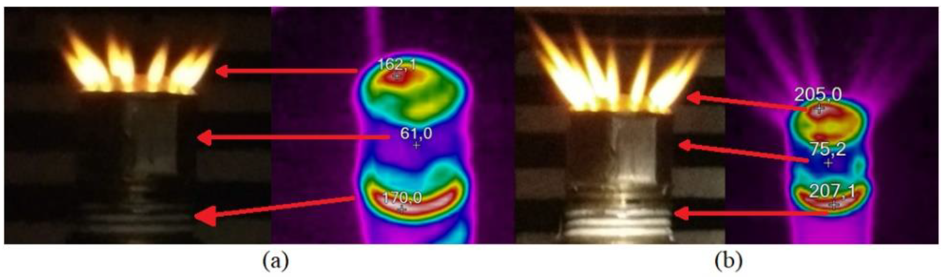
A drastic change in the luminous zone of the flame (top to bottom) is observed as the test progresses. This is due to the initial build-up and drag of the electrolyte. Energies 13 05526 i001
The change in the luminosity of the flame is attributed to the decrease in the volume of hydrogen and an increase in the volume of water vapor in the mixture. The increment of water vapor in the gas mixture instigates a cooling of the flame, thus causing a decrease in temperature. Energies 13 05526 i002
A decrease in the thickness of the flames is observed, although the length of the flames shows insignificant change, which is due to the decrease in the volume of hydrogen in the gas mixture (OH2G-water vapor). Therefore, a flow rate of 2.50 sL min−1 of OH2G is the optimal operating condition. Energies 13 05526 i003
If the electrolyzer works at higher flows (3.5 sL min−1) the increment of water vapor in the gas mixture instigates a cooling of the flame, thus causing a decrease in the temperature of the flame which could result in the flame being extinguished during the test. Energies 13 05526 i004
Publisher’s Note: MDPI stays neutral with regard to jurisdictional claims in published maps and institutional affiliations.

