A Review of the Integrated Design and Control of Electrified Vehicles


Abstract
1. Introduction
2. Energy-Aware Design and Control Optimization
2.1. Topology Generation
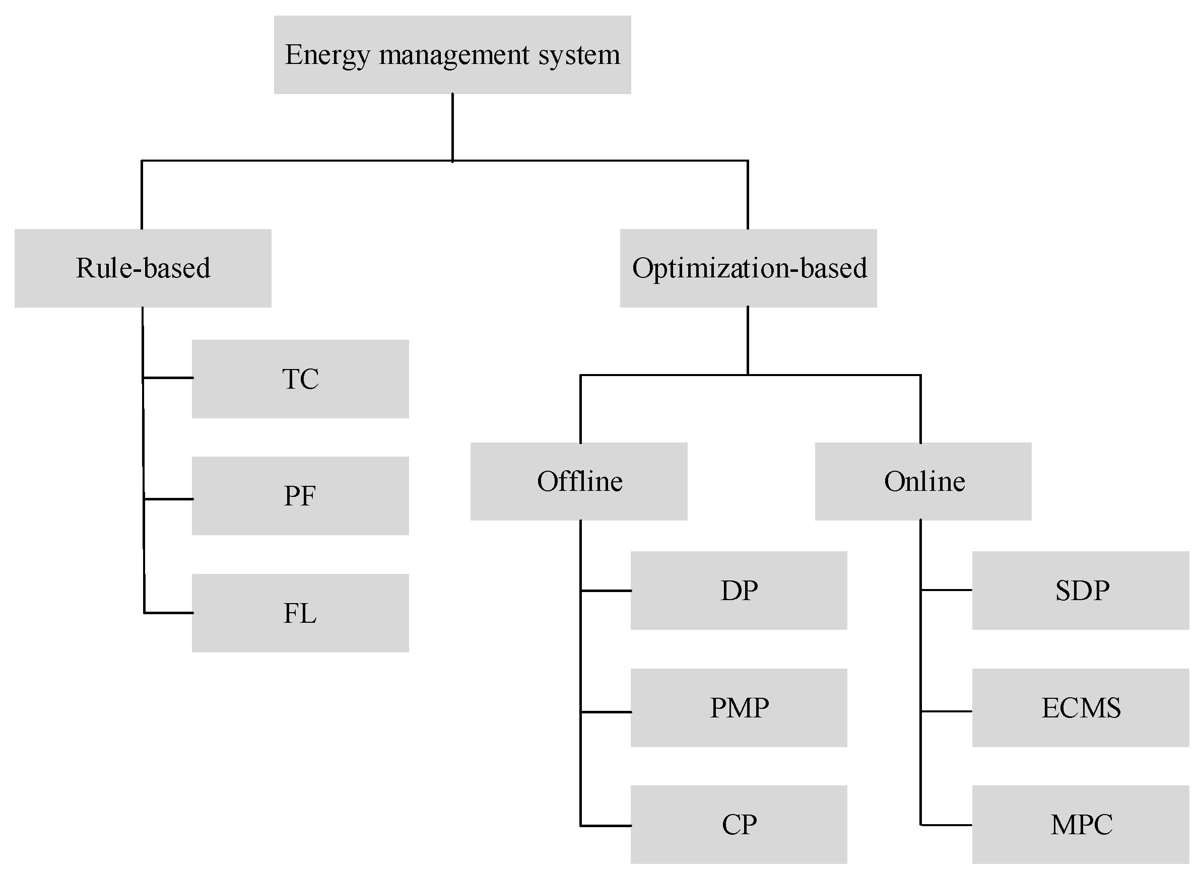
2.2. Control Optimization
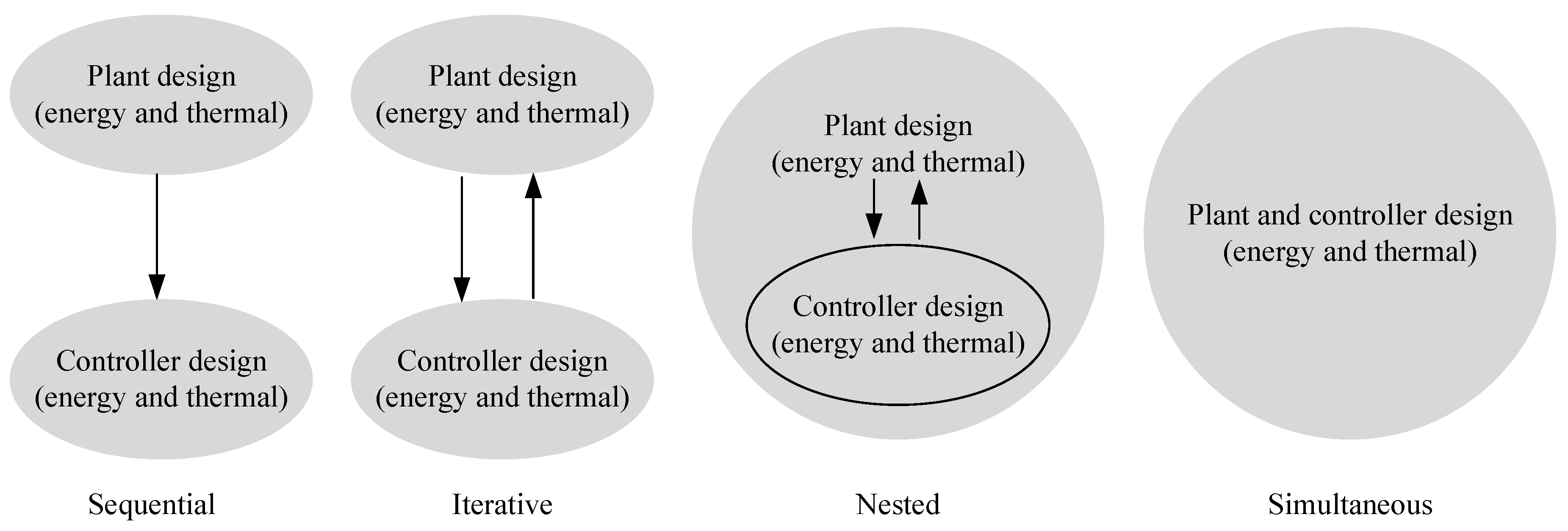
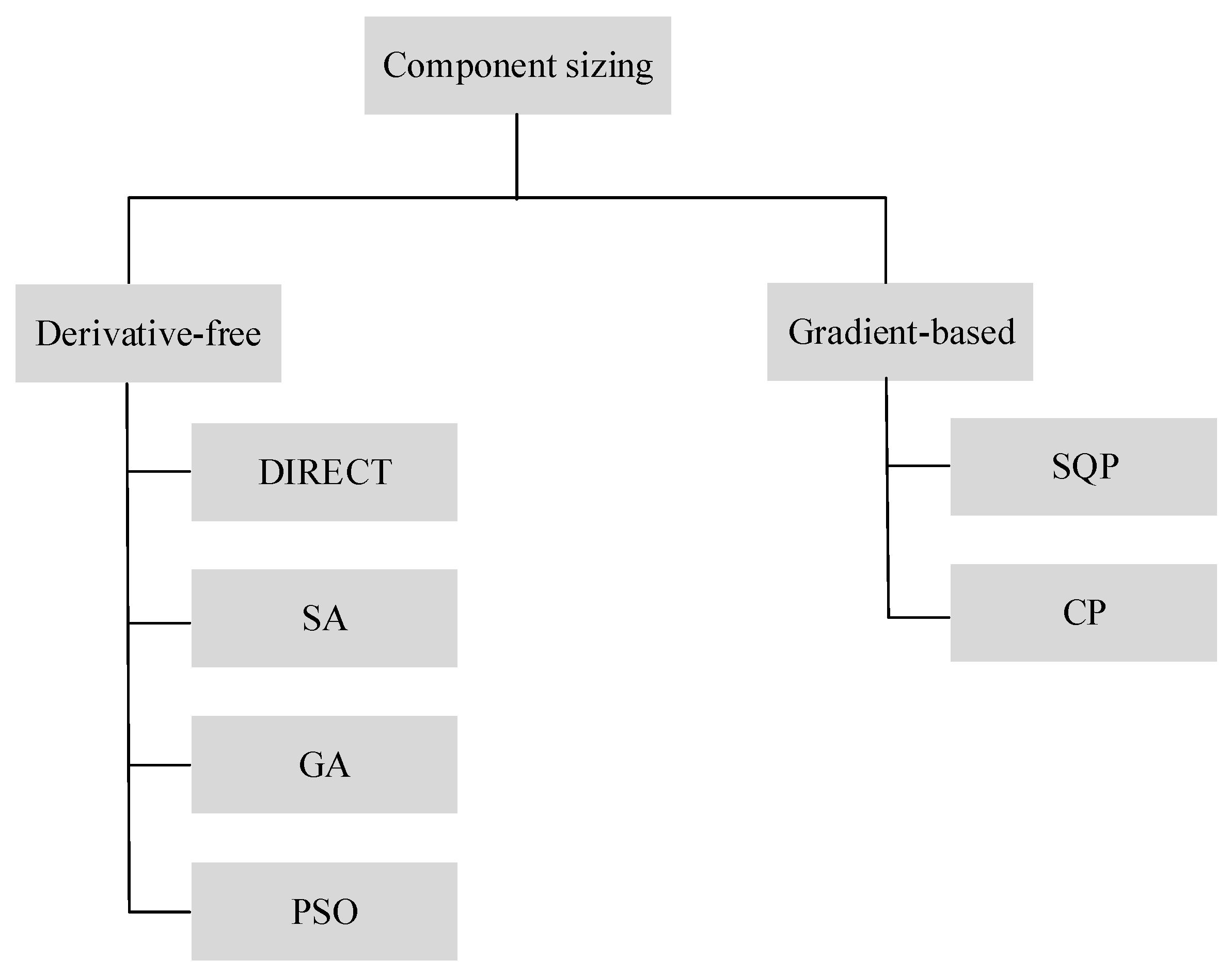
2.3. Combined Size and Control Optimization
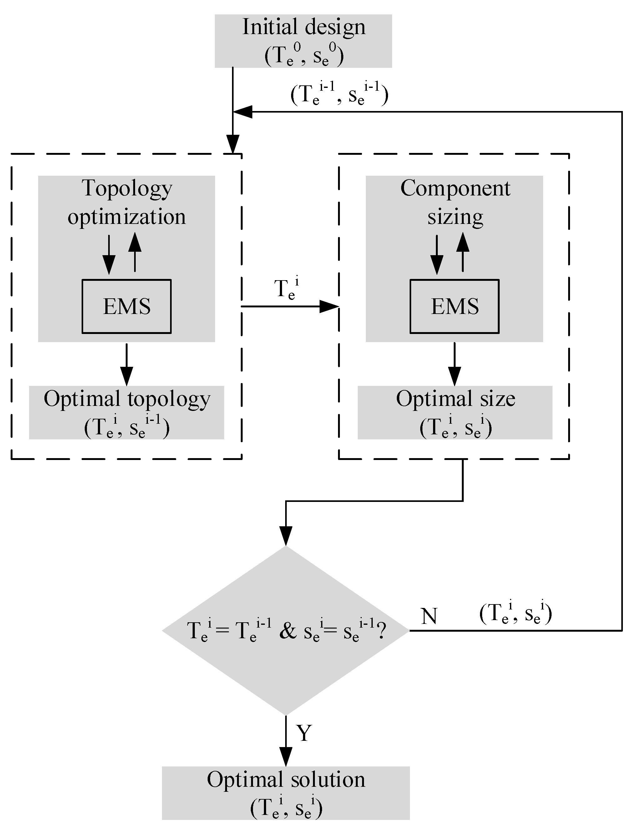
2.4. Combined Topology, Size and Control Optimization
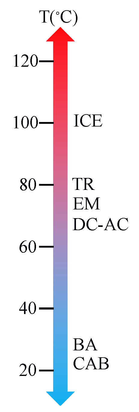
3. Thermal-Aware Design and Control Optimization
3.1. Topology Generation
3.2. Control Optimization
3.3. Size Optimization
3.4. Topology Optimization
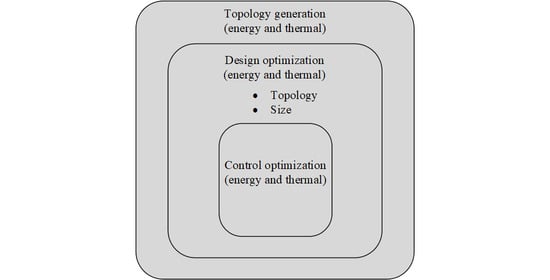
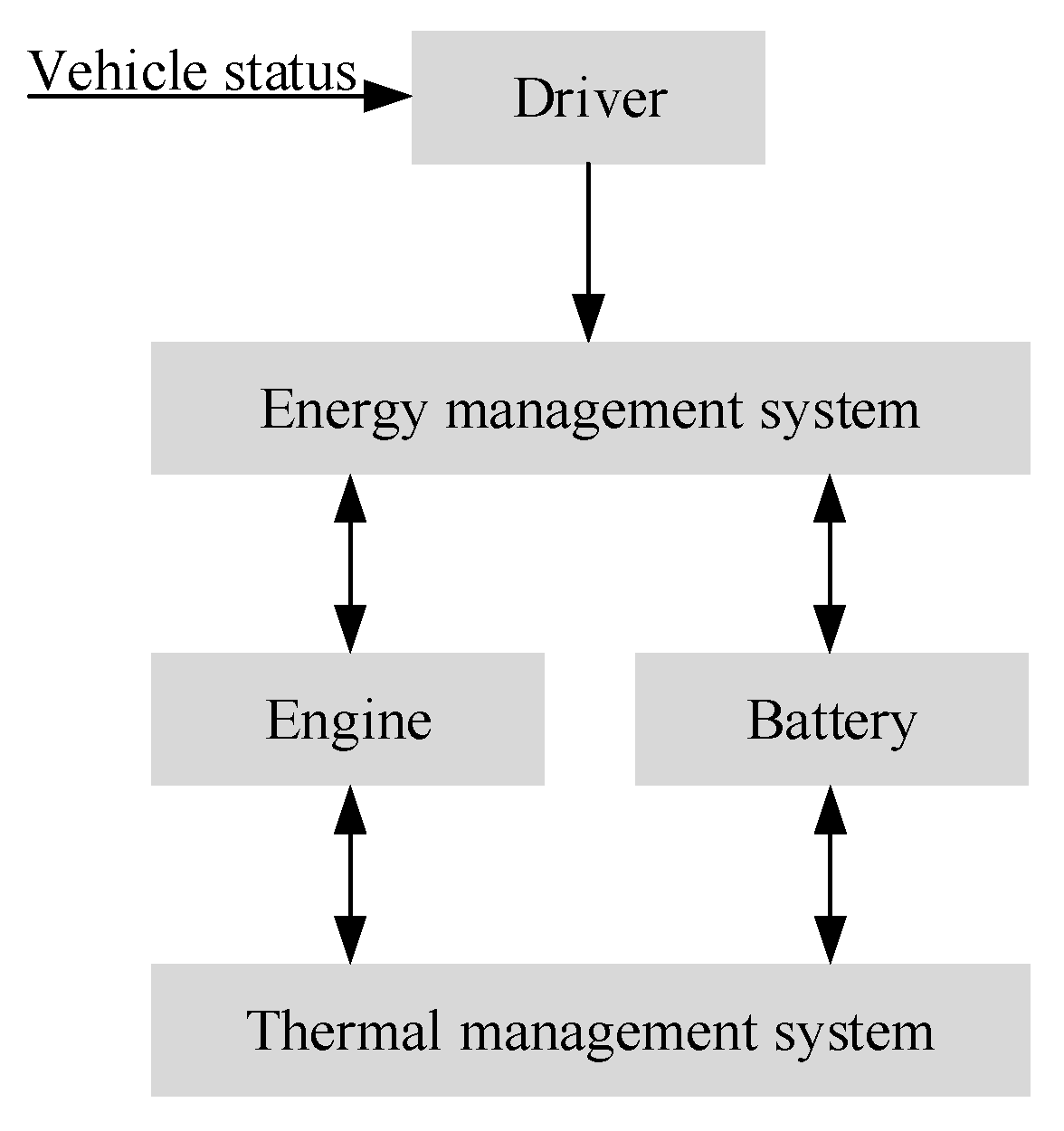
4. Energy and Thermal-Aware Design and Control Optimization
4.1. Topology Generation
4.2. Control Optimization
5. Observations and Future Trends
5.1. Controller Design
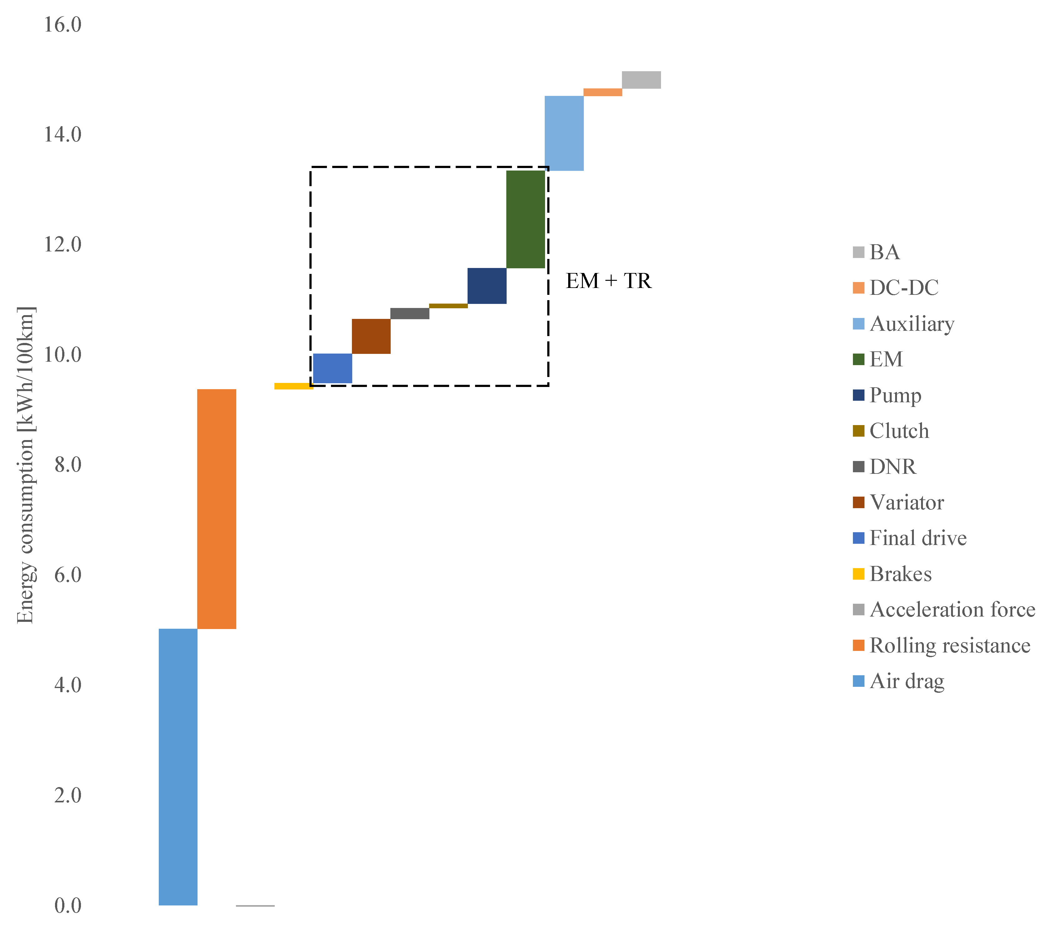
5.2. Waste Heat Recovery
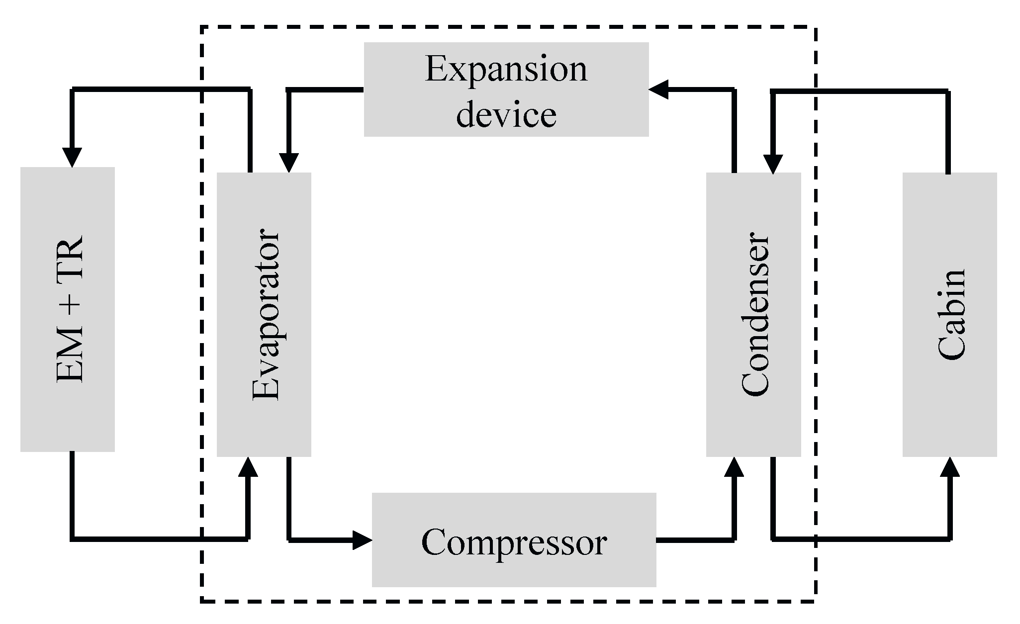
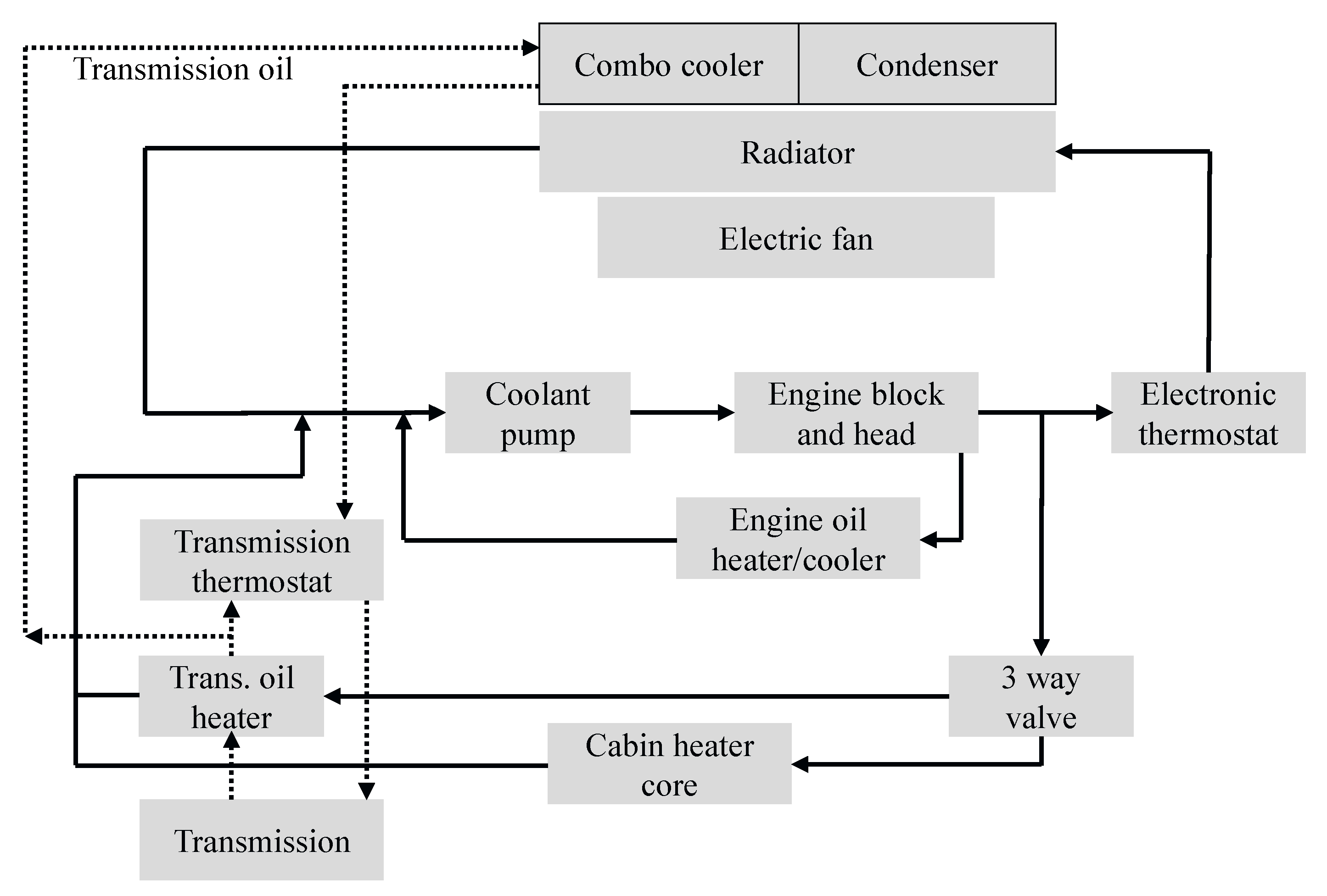
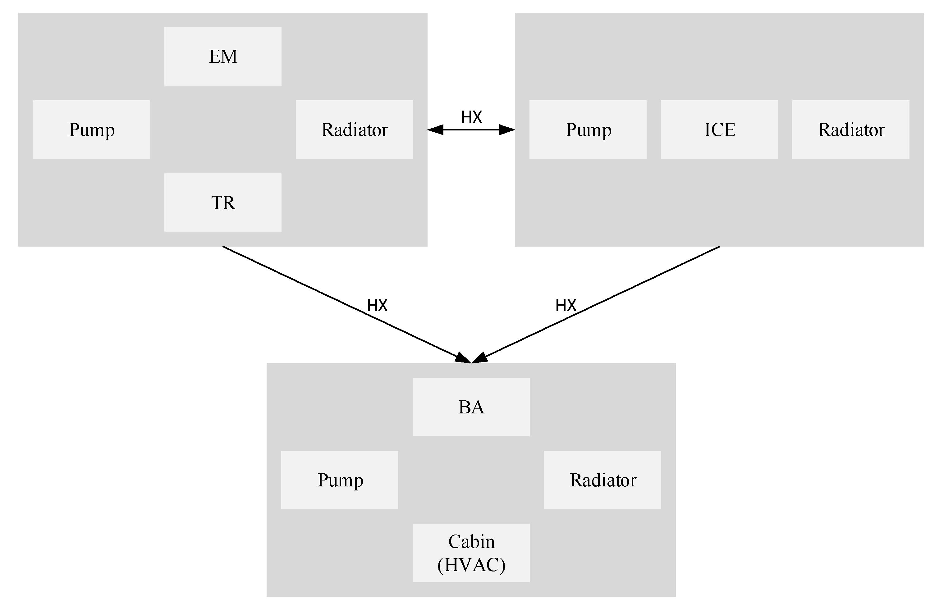
5.3. Heat Exchange
5.4. Transition to Electric Vehicles
5.5. Plant Design
6. Conclusions
Author Contributions
Funding
Acknowledgments
Conflicts of Interest
Abbreviations
| AC | Air Conditioning |
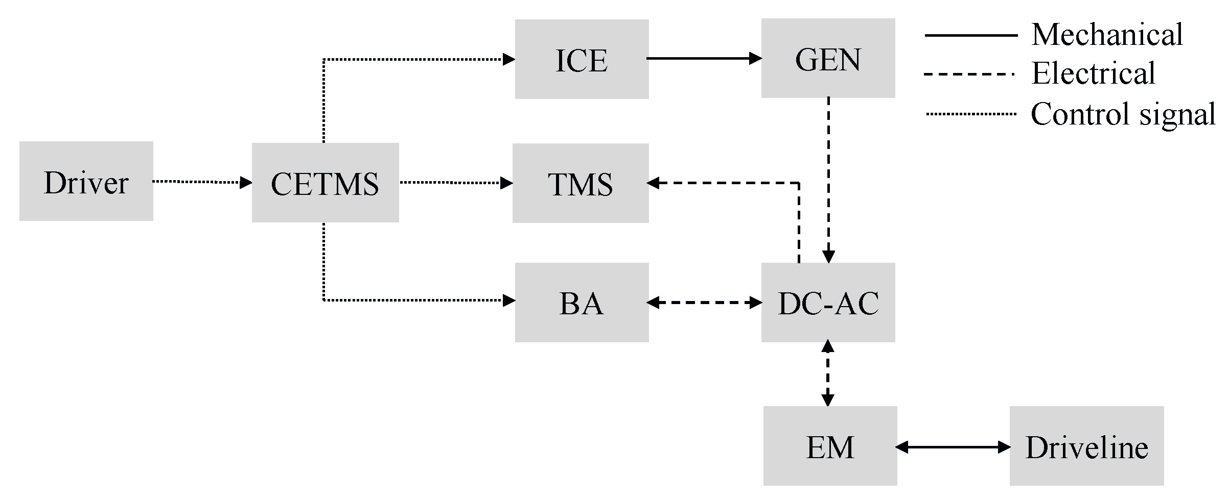
| BA | Battery |
| BER | Brake Energy Recuperation |
| CAB | Cabin |
| CAC | Charge Air Cooler |
| CETMS | Combined Energy and Thermal Management System |
| CH | Charging |
| CP | Convex Programming |
| CVT | Continuously Variable Transmission |
| DC | Direct Current |
| DIRECT | Dividing Rectangles |
| DNR | Drive, Neutral, and Reverse |
| DO | Distributed Optimization |
| DP | Dynamic Programming |
| ECMS | Equivalent Consumption Minimization Strategy |
| EM | Electric Machine |
| EMS | Energy Management System |
| EP | Electric Pump |
| EV | Electric Vehicle |
| FL | Fuzzy Logic |
| GA | Genetic Algorithm |
| GEN | Generator |
| HEV | Hybrid Electric Vehicle |
| HVAC | Heating, Ventilation, and Air Conditioning |
| ICE | Internal Combustion Engine |
| MA | Motor Assist |
| MINP | Mixed Integer Nonlinear Programming |
| MP | Mechanical Pump |
| MPC | Model Predictive Control |
| OB | Optimization-based |
| PF | Power Follower |
| PG | Planetary Gear |
| PI | Proportional-Integral |
| PMP | Pontryagin’s Minimum Principle |
| PSO | Particle Swarm Optimization |
| RB | Rule-based |
| SA | Simulated Annealing |
| SDP | Stochastic Dynamic Programming |
| SETMS | Separate Energy and Thermal Management System |
| SQP | Sequential Quadratic Programming |
| TC | Thermostat Control |
| TCO | Total Cost of Ownership |
| TMS | Thermal Management System |
| TR | Transmission |
References
- Yuan, R.; Fletcher, T.; Ahmedov, A.; Kalantzis, N.; Pezouvanis, A.; Dutta, N.; Watson, A.; Ebrahimi, K. Modelling and Co-simulation of Hybrid Vehicles: A Thermal Management Perspective. Appl. Therm. Eng. 2020, 180, 115883. [Google Scholar] [CrossRef]
- Tao, X. Design, Modeling and Control of a Thermal Management System for Hybrid Electric Vehicles. Ph.D. Thesis, Clemson University, Clemson, SC, USA, 2016. [Google Scholar]
- Shojaei, S.; McGordon, A.; Robinson, S.; Marco, J.; Jennings, P. Developing a Model for Analysis of the Cooling Loads of a Hybrid Electric Vehicle by Using Co-simulations of Verified Submodels. Proc. Inst. Mech. Eng. Part D J. Autom. Eng. 2018, 232, 766–784. [Google Scholar] [CrossRef]
- Biswas, S. Thermal Management System and Performance Characteristics of Electric Vehicle; SAE Technical Paper 2020-28-0022; SAE International: Warrendale, PA, USA, 2020. [Google Scholar]
- Amini, M.R.; Kolmanovsky, I.; Sun, J. Hierarchical MPC for Robust Eco-cooling of Connected and Automated Vehicles and Its Application to Electric Vehicle Battery Thermal Management. IEEE Trans. Control Syst. Technol. 2020, 1–13. [Google Scholar] [CrossRef]
- Lei, Z.; Qin, D.; Hou, L.; Peng, J.; Liu, Y.; Chen, Z.A. Adaptive Equivalent Consumption Minimization Strategy for Plug-in Hybrid Electric Vehicles based on Traffic Information. Energy 2020, 190. [Google Scholar] [CrossRef]
- Afzal, A.; Mohammed Samee, A.D.; Abdul Razak, R.K.; Ramis, M.K. Thermal management of Modern Electric Vehicle Battery Systems (MEVBS). J. Therm. Anal. Calorim. 2020. [Google Scholar] [CrossRef]
- Silvas, E.; Hofman, T.; Murgovski, N.; Etman, L.F.P.; Steinbuch, M. Review of Optimization Strategies for System-Level Design in Hybrid Electric Vehicles. IEEE Trans. Veh. Technol. 2017, 66, 57–70. [Google Scholar] [CrossRef]
- Guzzella, L.; Sciarretta, A. Vehicle Propulsion Systems: Introduction to Modeling and Optimization, 2nd ed.; Springer: Berlin, Germany, 2010. [Google Scholar]
- Zhuang, W.; Zhang, X.; Peng, H.; Wang, L. Simultaneous Optimization of Topology and Component Sizes for Double Planetary Gear Hybrid Powertrains. Energies 2016, 9, 411. [Google Scholar]
- Park, S. A Comprehensive Thermal Management System Model for Hybrid Electric Vehicles. Ph.D. Thesis, University of Michigan, Ann Arbor, MI, USA, 2011. [Google Scholar]
- Liu, J.; Peng, H. A Systematic Design Approach for Two Planetary Gear Split Hybrid Vehicles. Veh. Syst. Dyn. 2010, 48, 1395–1412. [Google Scholar] [CrossRef]
- Moura, S.J.; Callaway, D.S.; Fathy, H.K.; Stein, J.L. Tradeoffs between Battery Energy Capacity and Stochastic Optimal Power Management in Plug-in Hybrid Electric Vehicles. J. Power Sources 2010, 195, 2979–2988. [Google Scholar] [CrossRef]
- Chan, C.C.; Bouscayrol, A.; Chen, K. Electric, Hybrid, and Fuel-cell Vehicles: Architectures and Modeling. IEEE Trans. Veh. Technol. 2010, 59, 589–598. [Google Scholar] [CrossRef]
- Zhang, X.; Li, C.-T.; Kum, D.; Peng, H. Prius+ and Volt-: Configuration Analysis of Power-Split Hybrid Vehicles with a Single Planetary Gear. IEEE Trans. Veh. Technol. 2012, 61, 3544–3552. [Google Scholar] [CrossRef]
- Dagci, O.H.; Peng, H.; Grizzle, J.W. Hybrid Electric Powertrain Design Methodology with Planetary Gear Sets for Performance and Fuel Economy. IEEE Access 2018, 6, 9585–9602. [Google Scholar] [CrossRef]
- Bayrak, A.E.; Kang, N.; Papalambros, P. Decomposition-based Design Optimization of Hybrid Electric Powertrain Arhitectures: Simultaneous Configuration and Sizing Design. J. Mech. Des. 2016, 138. [Google Scholar] [CrossRef]
- Silvas, E.; Hofman, T.; Serebrenik, A.; Steinbuch, M. Functional and Cost-based Automatic Generator for Hybrid Vehicles Topologies. IEEE/ASME Trans. Mechatronics 2015, 20, 1561–1572. [Google Scholar] [CrossRef]
- Johri, R.; Filipi, Z. Optimal Energy Management of a Series Hybrid Vehicle with Combined Fuel Economy and Low-emission Objectives. Proc. Inst. Mech. Eng. Part D J. Autom. Eng. 2014, 228, 1424–1439. [Google Scholar] [CrossRef]
- Shabbir, W.; Evangelou, S.A. Threshold-changing Control Strategy for Series Hybrid Electric Vehicles. Appl. Energy 2019, 235, 761–775. [Google Scholar] [CrossRef]
- Singh, K.V.; Bansal, H.O.; Singh, D. Feed-forward Modeling and Real-time Implementation of an Intelligent Fuzzy Logic-based Energy Management Strategy in a Series–parallel Hybrid Electric Vehicle to Improve Fuel Economy. Electr. Eng. 2020, 102, 967–987. [Google Scholar] [CrossRef]
- Ehsani, M.; Gao, Y.; Emadi, A. Modern Electric, Hybrid Electric, and Fuel Cell Vehicles: Fundamentals, Theory, and Design, 2nd ed.; CRC: Boca Raton, FL, USA, 2010. [Google Scholar]
- Vinot, E.; Trigui, R.; Cheng, Y.; Espanet, C.; Bouscayrol, A.; Reinbold, V. Improvement of an EVT-based HEV Using Dynamic Programming. IEEE Trans. Veh. Technol. 2014, 63, 40–50. [Google Scholar] [CrossRef]
- Kim, N.; Cha, S.; Peng, H. Optimal Control of Hybrid Electric Vehicles based on Pontryagin’s Minimum Principle. IEEE Trans. Control Syst. Technol. 2011, 19, 1279–1287. [Google Scholar]
- Hadj-Said, S.; Colin, G.; Ketfi-Cherif, A.; Chamaillard, Y. Convex Optimization for Energy Management of Parallel Hybrid Electric Vehicles. IFAC-PapersOnLine 2016, 49, 271–276. [Google Scholar] [CrossRef]
- Opila, D.F.; Wang, X.; McGee, R.; Grizzle, J.W. Real-time Implementation and Hardware Testing of a Hybrid Vehicle Energy Management Controller based on Stochastic Dynamic Programming. J. Dyn. Syst. Meas. Control 2013, 135. [Google Scholar] [CrossRef]
- Nüesch, T.; Cerofolini, A.; Mancini, G.; Cavina, N.; Onder, C.; Guzzella, L. Equivalent Consumption Minimization Strategy for the Control of Real Driving NOx Emissions of a Diesel Hybrid Electric Vehicle. Energies 2014, 7, 3148–3178. [Google Scholar]
- Borhan, H.; Vahidi, A.; Phillips, A.M.; Kuang, M.L.; Kolmanovsky, I.V.; Di Cairano, S. MPC-based Energy Management of a Power-split Hybrid Electric Vehicle. IEEE Trans. Control Syst. Technol. 2012, 20, 593–603. [Google Scholar] [CrossRef]
- Sundström, O.; Guzzella, L.; Soltic, L.P. Torque-assist Hybrid Electric Powertrain Sizing: From Optimal Control towards a Sizing Law. IEEE Trans. Control Syst. Technol. 2010, 18, 837–849. [Google Scholar] [CrossRef]
- Pourabdollah, M.; Murgovski, N.; Grauers, A.; Egardt, B. Optimal Sizing of a Parallel Phev Powertrain. IEEE Trans. Veh. Technol. 2013, 62, 2469–2480. [Google Scholar] [CrossRef]
- Sinoquet, D.; Rousseau, G.; Milhau, Y. Design Optimization and Optimal Control for Hybrid Vehicles. Optim. Eng. 2011, 12, 199–213. [Google Scholar] [CrossRef]
- Ma, C.; Ko, S.Y.; Jeong, K.Y.; Kim, H.S. Design Methodology of Component Design Environment for PHEV. Int. J. Automot. Technol. 2013, 14, 785–795. [Google Scholar] [CrossRef]
- Patil, R.; Adornato, B.; Filipi, Z. Design Optimization of a Series Plug-in Hybrid Electric Vehicle for Real-World Driving Conditions. SAE Int. J. Engines 2010, 3, 655–665. [Google Scholar] [CrossRef][Green Version]
- Geller, B.; Bradley, T. Objective Comparison of Hybrid Vehicles through Simulation Optimization; SAE Technical Paper 2011-01-0943; SAE International: Warrendale, PA, USA, 2011. [Google Scholar]
- Fang, L.; Qin, S.; Xu, G.; Li, T.; Zhu, K. Simultaneous Optimization for Hybrid Electric Vehicle Parameters based on Multi-objective Genetic Algorithms. Energies 2011, 4, 532–544. [Google Scholar]
- Ebbesen, S.; Dönitz, C.; Guzzella, L. Particle Swarm Optimisation for Hybrid Electric Drive-train Sizing. Int. J. Veh. Des. 2012, 58, 181–199. [Google Scholar] [CrossRef]
- Silvas, E. Integrated Optimal Design for Hybrid Electric Vehicles. Ph.D. Thesis, Eindhoven University of Technology, Eindhoven, The Netherlands, 2015. [Google Scholar]
- Pourabdollah, M.; Murgovski, N.; Grauers, A.; Egardt, B.A. Iterative Dynamic Programming/Convex Optimization Procedure for Optimal Sizing and Energy Management of PHEVs. IFAC Proc. Vol. 2014, 47, 6606–6611. [Google Scholar] [CrossRef]
- Sezer, V.; Gokasan, M.; Bogosyan, S. A Novel ECMS and Combined Cost Map Approach for High-efficiency Series Hybrid Electric Vehicles. IEEE Trans. Veh. Technol. 2011, 60, 3557–3570. [Google Scholar] [CrossRef]
- Lee, H.; Song, C.; Kim, N.; Cha, S.W. Comparative Analysis of Energy Management Strategies for HEV: Dynamic Programming and Reinforcement Learning. IEEE Access 2020, 8, 67112–67123. [Google Scholar] [CrossRef]
- Ebbesen, S. Optimal Sizing and Control of Hybrid Electric Vehicles. Ph.D. Thesis, ETH Zurich, Zurich, Switzerland, 2012. [Google Scholar]
- Zhu, J.; Chen, L.; Wang, X.; Yu, L. Bi-level Optimal Sizing and Energy Management of Hybrid Electric Propulsion Systems. Appl. Energy 2020, 260, 114–134. [Google Scholar] [CrossRef]
- Bianchi, D.; Rolando, L.; Serrao, L.; Onori, S.; Rizzoni, G.; Al-Khayat, N.; Hsieh, T.-M.; Kang, P. Layered Control Strategies for Hybrid Electric Vehicles based on Optimal Control. Int. J. Electr. Hybrid Veh. 2011, 3, 191–217. [Google Scholar] [CrossRef]
- Hofman, T.; Ebbesen, S.; Guzzella, L. Topology Optimization for Hybrid Electric Vehicles with Automated Transmissions. IEEE Trans. Veh. Technol. 2012, 6, 2442–2451. [Google Scholar] [CrossRef]
- Nüesch, T.; Ott, T.; Ebbesen, S.; Guzzella, L. Cost and Fuel-Optimal Selection of HEV Topologies using Particle Swarm Optimization and Dynamic Programming. In Proceedings of the 2012 American Control Conference, Montreal, QC, Canada, 27–29 June 2012. [Google Scholar]
- Bennion, K.; Thornton, M. Integrated Vehicle Thermal Management for Advanced Vehicle Propulsion Technologies; Technical Report; National Renewable Energy Laboratory: Golden, CO, USA, 2010. [Google Scholar]
- Fletcher, T.; Kalantzis, N.; Ahmedov, A.; Yuan, R.; Ebrahimi, K.; Dutta, N.; Price, C. Holistic Thermal Energy Modelling for Full Hybrid Electric Vehicles (HEVs); SAE Technical Paper 2020-01-0151; SAE International: Warrendale, PA, USA, 2020. [Google Scholar]
- Tao, X.; Wagner, J. A Thermal Management System for the Battery Pack of a Hybrid Electric Vehicle: Modeling and Control. Proc. Inst. Mech. Eng. Part D J. Automob. Eng. 2016, 230, 190–201. [Google Scholar] [CrossRef]
- Tao, X.; Zhou, K.; Wagner, J.; Hofmann, H.A. Electric Motor Thermal Management System for Hybrid Vehicles: Modelling and Control. Int. J. Veh. Perform. 2016, 2, 207–227. [Google Scholar]
- Zhang, X.; Ivanco, A.; Tao, X.; Wagner, J.; Filipi, Z. Optimization of the Series-hev Control with Consideration of the Impact of Battery Cooling Auxiliary Losses. SAE Int. J. Altern. Power 2014, 3, 234–243. [Google Scholar] [CrossRef]
- Wang, T.; Jagarwal, A.; Wagner, J.R.; Fadel, G. Optimization of an Automotive Radiator Fan Array Operation to Reduce Power Consumption. IEEE/ASME Trans. Mechatronics 2015, 20, 2359–2369. [Google Scholar] [CrossRef]
- Lopez-Sanz, J.; Ocampo-Martinez, C.; Álvarez-Flórez, J.; Moreno-Eguilaz, M.; Ruiz-Mansilla, R.; Kalmus, J.; Gräeber, M.; Lux, G. Thermal Management in Plug-in Hybrid Electric Vehicles: A Real-time Nonlinear Model Predictive Control Implementation. IEEE Trans. Veh. Technol. 2017, 66, 7751–7760. [Google Scholar] [CrossRef]
- Saha, J.; Chen, H.; Rahman, S. Model based Design and Optimization of Vehicle Thermal Management System; SAE Technical Paper 2016-01-0283; SAE International: Warrendale, PA, USA, 2016. [Google Scholar]
- Hughes, C.; Wiseman, M. Feasibility of Intelligent Control Strategies to Reduce Cooling System Size; SAE Technical Paper 2001-01-1759; SAE International: Warrendale, PA, USA, 2001. [Google Scholar]
- Johnson, R.W.; Evans, J.L.; Jacobsen, P.; Thompson, J.R.; Christopher, M. The Changing Automotive Environment: High-Temperature Electronics. IEEE Trans. Electron. Packag. Manuf. 2004, 27, 164–176. [Google Scholar] [CrossRef]
- Cho, H.; Jung, D.; Filipi, Z.; Assanis, D.N.; Vanderslice, J.; Bryzik, W. Application of Controllable Electric Coolant Pump for Fuel Economy and Cooling Performance Improvement. J. Eng. Gas Turbines Power 2007, 129, 239–244. [Google Scholar] [CrossRef]
- Park, S.; Kokkolaras, M.; Malikopoulos, A.; AbdulNour, B.; Sedarous, J.; Jung, D. Thermal Management System Modeling and Optimization for Heavy Hybrid Electric Military Vehicles. In Proceedings of the 2010 NDIA Ground Vehicle Systems Engineering and Technology Symposium, Dearborn, MI, USA, 17–19 August 2010. [Google Scholar]
- Tao, X.; Wagner, J. Optimization of a Military Ground Vehicle Engine Cooling System Heat Exchanger—Modeling and Size Scaling; SAE Technical Paper 2017-01-0259; SAE International: Warrendale, PA, USA, 2017. [Google Scholar]
- Park, S.; Jung, D. Design of Vehicle Cooling System Architecture for a Heavy Duty Series-hybrid Electric Vehicle Using Numerical System Simulations. J. Eng. Gas Turbines Power 2010, 132. [Google Scholar] [CrossRef]
- Wei, C.; Hofman, T.; Ilhan Caarls, E.; van Iperen, R. Evolution and Classification of Energy and Thermal Management Systems in Electrified Powertrains. In Proceedings of the 2019 IEEE Vehicle Power and Propulsion Conference, Hanoi, Vietnam, 14–17 October 2019. [Google Scholar]
- Zhang, X. Supervisory Control Optimization for a Series Hybrid Electric Vehicle with Consideration of Battery Thermal Management and Aging. Ph.D. Thesis, Clemson University, Clemson, SC, USA, 2016. [Google Scholar]
- Pham, T.H. Integrated Energy and Battery Life Management for Hybrid Vehicles. Ph.D. Thesis, Eindhoven University of Technology, Eindhoven, The Netherlands, 2015. [Google Scholar]
- Jiménez-Espadafor, F.J.; Guerrero, D.P.; Trujillo, E.C.; García, M.T.; Wideberg, J. Fully Optimized Energy Management for Propulsion, Thermal Cooling and Auxiliaries of a Serial Hybrid Electric Vehicle. Appl. Therm. Eng. 2015, 91, 694–705. [Google Scholar] [CrossRef]
- Romijn, T.C.J.; Donkers, M.C.F.; Kessels, J.T.B.A.; Weiland, S. A Distributed Optimization Approach for Complete Vehicle Energy Management. IEEE Trans. Control Syst. Technol. 2019, 27, 964–980. [Google Scholar] [CrossRef]
- Pham, T.H.; Kessels, J.T.B.A.; van den Bosch, P.P.J.; Huisman, R.G.M.; Nevels, R.M.P.A. On-line Energy and Battery Thermal Management for Hybrid Electric Heavy-Duty Truck. In Proceedings of the 2013 American Control Conference, Washington, DC, USA, 17–19 June 2013. [Google Scholar]
- Ngo, V.; Hofman, T.; Steinbuch, M.; Serrarens, A. Optimal Control of the Gearshift Command for Hybrid Electric Vehicles. IEEE Trans. Veh. Technol. 2012, 61, 3531–3543. [Google Scholar] [CrossRef]
- Nüesch, T.; Elbert, P.; Flankl, M.; Onder, C.; Guzzella, L. Convex Optimization for the Energy Management of Hybrid Electric Vehicles Considering Engine Start and Gearshift Costs. Energies 2014, 7, 834–856. [Google Scholar]
- Böhme, T.J.; Frank, B. Hybrid Systems, Optimal control and Hybrid Vehicles: Theory, Methods and Applications; Springer: Cham, Switzerland, 2017. [Google Scholar]
- Tate, E.D.; Grizzle, J.W.; Peng, H. SP-SDP for Fuel Consumption and Tailpipe Emissions Minimization in an EVT Hybrid. IEEE Trans. Control Syst. Technol. 2010, 18, 673–687. [Google Scholar] [CrossRef]
- Serrao, L.; Onori, S.; Sciarretta, A.; Guezennec, Y.; Rizzoni, G. Optimal Energy Management of Hybrid Electric Vehicles Including Battery Aging. In Proceedings of the 2011 American Control Conference, San Francisco, CA, USA, 29 June–1 July 2011. [Google Scholar]
- Barbarisi, O.; Westervelt, E.R.; Vasca, F.; Rizzoni, G. Power Management Decoupling Control for a Hybrid Electric Vehicle. In Proceedings of the 44th IEEE Conference on Decision and Control, Seville, Spain, 12–15 December 2005. [Google Scholar]
- Wang, T.; Wagner, J. A Smart Engine Cooling System—Experimental Study of Integrated Actuator Transient Behavior; SAE Technical Paper 2015-01-1604; SAE International: Warrendale, PA, USA, 2015. [Google Scholar]
- Tao, X.; Zhou, K.; Ivanco, A.; Wagner, J.; Hofmann, H.; Filipi, Z. A Hybrid Electric Vehicle Thermal Management System—Nonlinear Controller Design; SAE Technical Paper 2015-01-1710; SAE International: Warrendale, PA, USA, 2015. [Google Scholar]
- Wei, C.; Hofman, T.; Ilhan Caarls, E.; van Iperen, R. Integrated Energy and Thermal Management for Electrified Powertrains. Energies 2019, 12, 2058. [Google Scholar]
- Wang, T.; Zhang, Y.; Peng, Z.; Shu, G. A Review of Researches on Thermal Exhaust Heat Recovery with Rankine Cycle. Renew. Sustain. Energy Rev. 2011, 15, 2862–2871. [Google Scholar] [CrossRef]
- Martins, J.; Goncalves, L.M.; Antunes, J.; Brito, F.P. Thermoelectric Exhaust Energy Recovery with Temperature Control through Heat Pipes. In Proceedings of the SAE 2011 World Congress & Exhibition, Detroit, MI, USA, 12–14 April 2011. [Google Scholar]
- Merz, F.; Sciarretta, A.; Dabadie, J.-C.; Serrao, L.O. The Optimal Thermal Management of Hybrid-electric Vehicles with Heat Recovery Systems. Oil Gas Sci. Technol. 2012, 67, 601–612. [Google Scholar] [CrossRef]
- Qi, Z. Advances on Air Conditioning and Heat Pump System in Electric Vehicles—A Review. Renew. Sustain. Energy Rev. 2014, 38, 754–764. [Google Scholar] [CrossRef]
- Wei, C.; Hofman, T.; Ilhan Caarls, E.; van Iperen, R. Energy-efficiency Improvement Potential of Electric Vehicles Considering Transmission Temperature. IFAC-PapersOnLine 2019, 52, 211–216. [Google Scholar] [CrossRef]
- Ahn, J.H.; Kang, H.; Lee, H.S.; Jung, H.W.; Baek, C.; Kim, Y. Heating Performance Characteristics of a Dual Source Heat Pump using Air and Waste Heat in Electric Vehicles. Appl. Energy 2014, 119, 1–9. [Google Scholar] [CrossRef]
- McFadden, C.; Hughes, K.; Raser, L.; Newcomb, T. Electrical Conductivity of New and Used Automatic Transmission Fluids. SAE Int. J. Fuels Lubr. 2016, 9, 519–526. [Google Scholar] [CrossRef]
- Dubouil, R.; Hetet, J.F.; Maiboom, A. Modelling of the Warm-up of a Spark Ignition Engine: Application to Hybrid Vehicles. In Proceedings of the SAE International Powertrains, Fuels and Lubricants Meeting, Kyoto, Japan, 30 August–2 September 2011. [Google Scholar]
- Titov, G.; Lustbader, J. Modeling Control Strategies and Range Impacts for Electric Vehicle Integrated Thermal Management Systems with MATLAB/Simulink; SAE Technical Paper 2017-01-0191; SAE International: Warrendale, PA, USA, 2017. [Google Scholar]
- Laboe, K.; Canova, M. Powertrain Waste Heat Recovery: A Systems Approach to Maximize Drivetrain Efficiency. In Proceedings of the ASME 2012 Internal Combustion Engine Division Spring Technical Conference, Torino, Italy, 6–9 May 2012. [Google Scholar]
- Tie, S.F.; Tan, C.W. A Review of Energy Sources and Energy Management System in Electric Vehicles. Renew. Sustain. Energy Rev. 2013, 20, 82–102. [Google Scholar] [CrossRef]
- Hofman, T.; Janssen, N.H.J. Integrated Design Optimization of the Transmission System and Vehicle Control for Electric Vehicles. IFAC-PapersOnLine 2017, 50, 10072–10077. [Google Scholar] [CrossRef]
- van der Sluis, F.; Römers, L.; van Spijk, G.; Hupkes, I. CVT, Promising Solutions for Electrification; Warrendale, PA, USA, SAE Technical Paper 2019-01-0359; SAE International, 2019. [Google Scholar]
- Scholl, M.; Minnerup, K.; Reiter, C.; Bernhardt, B.; Weisbrodt, E.; Newiger, S. Optimization of a Thermal Management System for Battery Electric Vehicles. In Proceedings of the 2019 Fourteenth International Conference on Ecological Vehicles and Renewable Energies (EVER), Monte-Carlo, Monaco, 8–10 May 2019. [Google Scholar]
- Pourabdollah, M.; Silvas, E.; Murgovski, N.; Steinbuch, M.; Egardt, B. Optimal Sizing of a Series PHEV: Comparison between Convex Optimization and Particle Swarm Optimization. IFAC-PapersOnLine 2015, 48, 16–22. [Google Scholar] [CrossRef]


| Strategy | Main Advantages | Main Disadvantages | Application |
|---|---|---|---|
| Rule-based [19,20,21] | Easy to implement | Tuning of many parameters Cycle- and configuration-dependent rules | Series and power-split HEV |
| DP [23] | Handling complex constraints Global optimal | Limited states and control variables Long computation time | Powers-split HEV |
| CP [25] | Low computation time Handling many states and control variables | Problem formulation in convex form | Parallel HEV |
| ECMS [27] | Real-time control Single objective | Equivalence factor sensitive to cycle Sub-optimal | Parallel HEV |
| MPC [28] | Predictive and adaptive Real-time implementation | Sensitive to model quality and prediction horizon | Power-split HEV |
| Strategy | Main Advantages | Main Disadvantages |
|---|---|---|
| Rule-based [31,32] | Relatively simple calculations | Non-optimal Cycle- and configuration-dependent sizes |
| Derivative-free [33,34,35,36] | Handling large design space Handling complex functions and constraints | Tuning of parameters Large number of function evaluations No guarantee of an optimal solution |
| Gradient-based [30,37] | Low computation time | Constraint handling Convex formulation |
| Strategy | Main Advantages | Main Disadvantages | Application |
|---|---|---|---|
| Sequential [39,40] | Easy to implement | No coupling between the plant and controller | Series and parallel HEV |
| Iterative [38] | Computationally efficient | Sub-optimal | Parallel HEV |
| Nested [37,41,42] | Solution optimality | Long computation time | Series and parallel HEV |
| Simultaneous [30] | Strong coupling between the plant and controller | Complex problem formulation | Parallel HEV |
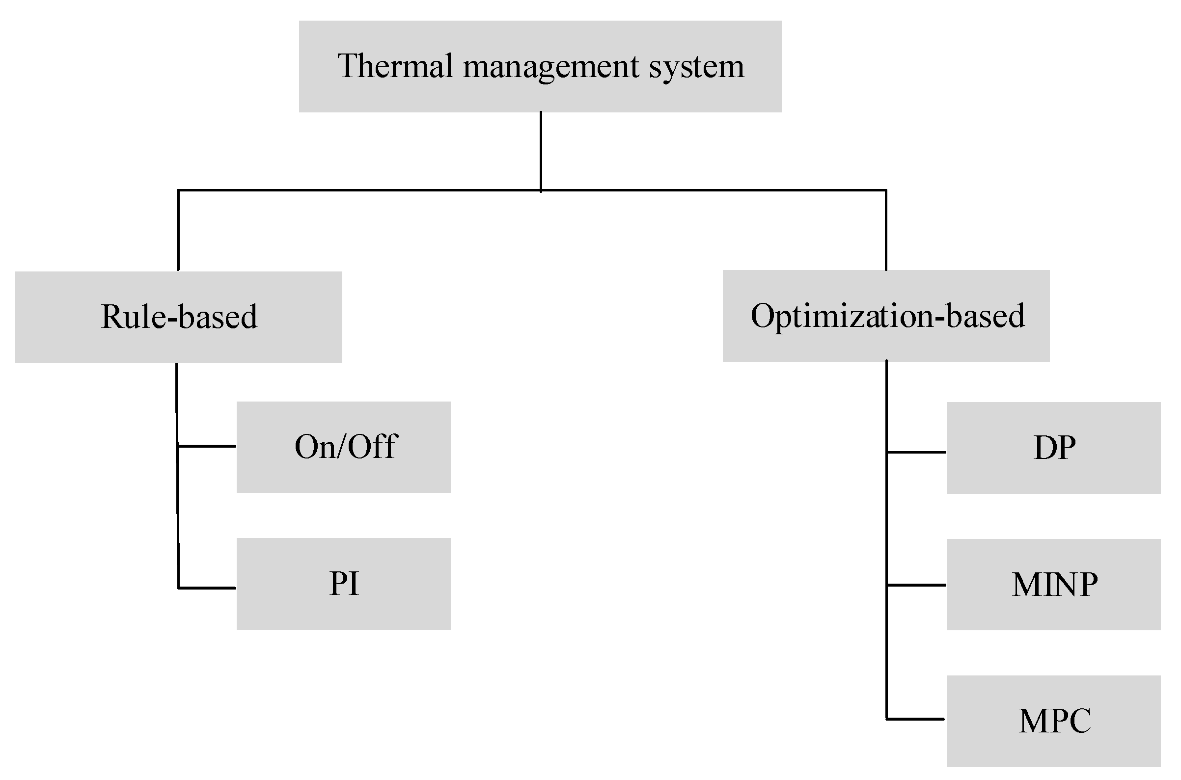
| Strategy | Main Advantages | Main Disadvantages | Application |
|---|---|---|---|
| On/Off [48] | Easy to implement | Unnecessary power consumption | Battery cooling system |
| PI [49] | Improved tracking performance | Tuning of parameters | Electric machine cooling system |
| DP [50] | Global optimal | Curse of dimensionality | Battery cooling system |
| MINP [51] | Handling continuous and integer variables | Not implementable | Engine cooling system |
| MPC [52] | Real-time implementation | Model fidelity | Electrical components of a parallel HEV |
| Control Strategy | Composition | Optimality | Causality | Application |
|---|---|---|---|---|
| SETMS | PF + On/Off | Sub-optimal | Causal | Heavy-duty series HEV powertrain [11] |
| TC + MPC | Sub-optimal | Causal | Battery pack of a series HEV [61] | |
| ECMS + On/Off | Sub-optimal | Causal | Battery of a hybrid electric truck [62] | |
| OB + MPC | Sub-optimal | Causal | HEV powertrain [2] | |
| CETMS | (RB, RB) | Sub-optimal | Causal | Engine and electrical power equipment of an HEV [63] |
| (RB, OB) | Sub-optimal | Causal | Engine and electrical power equipment of an HEV [63] | |
| (DO, On/Off) | Close-to-optimal | Acausal | Climate control system, refrigerated semitrailer, and air supply system [64] | |
| (DP, MPC) | Optimal | Acausal | Battery pack of a series HEV [50] |
Publisher’s Note: MDPI stays neutral with regard to jurisdictional claims in published maps and institutional affiliations. |
© 2020 by the authors. Licensee MDPI, Basel, Switzerland. This article is an open access article distributed under the terms and conditions of the Creative Commons Attribution (CC BY) license (http://creativecommons.org/licenses/by/4.0/).
Share and Cite
Wei, C.; Hofman, T.; Ilhan Caarls, E.; van Iperen, R. A Review of the Integrated Design and Control of Electrified Vehicles. Energies 2020, 13, 5454. https://doi.org/10.3390/en13205454
Wei C, Hofman T, Ilhan Caarls E, van Iperen R. A Review of the Integrated Design and Control of Electrified Vehicles. Energies. 2020; 13(20):5454. https://doi.org/10.3390/en13205454
Chicago/Turabian StyleWei, Caiyang, Theo Hofman, Esin Ilhan Caarls, and Rokus van Iperen. 2020. "A Review of the Integrated Design and Control of Electrified Vehicles" Energies 13, no. 20: 5454. https://doi.org/10.3390/en13205454
APA StyleWei, C., Hofman, T., Ilhan Caarls, E., & van Iperen, R. (2020). A Review of the Integrated Design and Control of Electrified Vehicles. Energies, 13(20), 5454. https://doi.org/10.3390/en13205454