Article

Variable Pitch Propeller for UAV-Experimental Tests

by
Maciej Podsędkowski
1,*,
Rafał Konopiński
1,
Damian Obidowski
2 and
Katarzyna Koter
1
1
Institute of Machine Tools and Production Engineering, Lodz University of Technology, 90924 Łódź, Poland
2
Institute of Turbomachinery, Lodz University of Technology, 90924 Łódź, Poland
*
Author to whom correspondence should be addressed.
Energies 2020, 13(20), 5264; https://doi.org/10.3390/en13205264
Submission received: 1 September 2020 / Revised: 1 October 2020 / Accepted: 3 October 2020 / Published: 10 October 2020
(This article belongs to the Section E: Electric Vehicles)

Abstract

:
Growth in application fields of unmanned aerial vehicles (UAVs) and an increase in their total number are followed by higher and higher expectations imposed on improvements in UAV propulsion and energy management systems. Most commercial vertical takeoff and landing (VTOL) UAVs employ a constant pitch propeller that forces a mission execution tradeoff in the majority of cases. An alternative solution, presented here, consists of the use of a variable pitch propeller. The paper summarizes experimental measurements of the propulsion system equipped with an innovative variable pitch rotor. The investigations incorporated characteristics of the rotor for no wind conditions and a new approach to optimize pitch settings in hover flight as a function of UAV weight and energy consumption. As UAV battery capacity is always limited, efficient energy management is the only way to increase UAV mission performance. The study shows that use of a variable pitch propeller can increase the maximal takeoff weight of the aircraft and improve power efficiency in hover, especially if load varies for different missions. The maximal thrust measured was 31% higher with respect to the original blade settings. The coefficient of thrust during hover showed an increase of 2.6% up to 7.5% for various pitch angles with respect to the original fixed propeller.

Graphical Abstract

1. Introduction

Since the early 1990s, dynamic development of small unmanned flying vehicles [1] can be observed. An important issue when designing and building them is to ensure best performance, which includes flight time [2], load capacity [3], the maximal distance that the unit can cover [4] and the maximal speed [5].
Currently, great emphasis is placed on high flight parameters resulting directly from the quality of propulsion system [6] and trajectory optimization [7]. Such a system usually consists of a battery, an engine speed controller (ESC), an engine and a propeller [8]. Propellers, which are usually used, have a constant pitch due to their simple construction [9]. Consequently, such propellers are adapted to specific flight conditions [10]. Therefore, it is impossible to achieve optimal performance while changing flight conditions.
A significant increase in interest in the commercial use of unmanned aerial vehicles (UAVs) for moving packages is visible [11,12]. It allows parcels to be delivered on time, even when the area is geologically unfavorable. Considering this advantage, many companies such as Amazon or DHL decided to introduce unmanned aerial vehicles into the transport industry [13]. There are also attempts to introduce small autonomous units to transport people [14].
The main priority in newly developed transport UAVs is the possibility of vertical takeoff and landing combined with a large operational range of these units. This goal requires the highest possible efficiency from the drone propulsion system. Since the drone flies in two basic configurations, with and without load, operating conditions of UAVs in the air are significantly different.
Flight conditions largely depend on the total weight of unit; therefore, the weight of load compared to the weight of drone has to be considered. To achieve optimal flight conditions, the right propeller should be selected for each configuration. However, it is practically impossible to exchange the propeller during flight. Therefore, a suitable solution would be to install mechanisms to change the rotor geometry, which would allow the propulsion system to adapt to flight conditions.
Many innovative designs of the powered-lift aircraft have been presented, such as a plane airframe structure with additional engines for vertical flight [15], a tail-sitter [16,17,18], a tiltrotor [19,20] and a tiltwing [21]. The majority of these solutions involve the use of fixed pitch propellers. They affect the selection options of propellers, since flight of the aircraft involves at least three phases, namely, takeoff, landing and cruise flight.
Although takeoff climb speed is low for powered-lifts, very high thrust during takeoff is necessary to lift up the entire aircraft with load. This requires propellers adapted to low flight speeds, i.e., those with a small pitch. For cruising flight, larger pitch propellers are demanded to maintain optimal performance. Since cruising speed can be very high, propeller selection is averaged. As a result, tradeoff must be defined; the outcome of this is a situation where the rotor does not reach its maximal speed and thrust during the start due to a high resistance torque of the propeller, and, on the other hand, the maximal speed is limited by the propeller pitch.
A solution to problems with limited propeller pitch capabilities is to use variable pitch propellers. This is a direction of drone development that was once seen for flying units. At the beginning of aviation development, propellers with a fixed pitch were used to propel the aircraft, but soon it turned out to be inefficient. Therefore, mechanisms allowing the pitch of propellers to be changed began to be used. At first, a ground adjustable pitch propeller, which allows pitch to be changed only on the ground when the device is stationary, was introduced. Then, mechanisms that could change the blade wedge angle during flight were introduced. The cause of those attempts was to achieve the best flight performance, especially speed. Nowadays, the drone market is entering a similar phase of development.
A technological development entails a possibility to miniaturize flying units. However, further extension of their capabilities requires optimization of flight parameters and an increase in performance. In order to adjust to this development trend, it is necessary to conduct research in the field of pitch change mechanisms adapted to small aircrafts and to analyze available propellers in terms of their applicability and performance.
Experimental and numerical studies were carried out on fixed pitch propellers for UAVs [22,23]. The research included examination of propeller parameters in stationary air [24] and in the wind tunnel [25,26], where the characteristics of propeller work during flight were examined. The research also concerned noise generated by propellers [27] and propeller behavior in crosswinds [28]. Rotors with variable pitch blades, intended for drones, were tested for helicopters [29,30,31], but there are still no data for small rotors for small unmanned fixed-wing or multi-rotor drones. The main reason for this is that on the market there are no readily available mechanisms that allow for a change of the blade pitch in an effective way. However, there are mechanisms adapted to small units [32,33,34]. These systems are primarily designed for elastic propellers with a diameter of about 10 inches and are not suitable for use in industry where a high load capacity is required. In addition, variable pitch propellers are used in flight control of quadrotor drones instead of controlling engine speed [35].
Mathematical models of variable pitch propellers, characterized by different levels of complexity, to calculate thrust and torque in particular, were investigated in [36]. A possible method to control motors in order to reduce drag was developed based on those models. The models were experimentally tested on a symmetrical airfoil blade propeller and one of them fits best the experimental data for this specific solution.
Currently, commercially available unmanned aerial vehicles solutions based on fixed pitch propellers are not always sufficiently efficient; therefore, they are not able to meet global market demand. A solution that can significantly increase the capabilities of drones is to use rotors with a variable pitch mechanism. A propulsion system equipped with a mechanism changing the rotor blade pitch angle can increase hovering thrust. This mechanism is especially devoted to vertical takeoff and landing (VTOL) systems, where takeoff and landing require high thrust. It is worth mentioning that the time of these operations is usually much shorter compared to the time of the entire flight. Thus, after takeoff, it is necessary to adjust the pitch of the blades to the flight speed in order to maximize efficiency.
The present paper presents test results of a modified, commercially available Fluxer 16 × 6 propeller. A novelty of the solution, with respect to current UAV power and thrust control systems, lies in a possibility to control variable pitch to increase efficiency of the hovering propulsion system and to produce large thrust. The research method and obtained results for this propeller are presented in the following sections.
In order to conduct the investigations, a dedicated test stand was designed and built. The tests conducted in standing air allowed one to determine basic characteristics of forces and moments, together with efficiency for different angles of attack of blades. On the basis of the characteristics, an analysis aiming at altering optimally the propeller pitch in order to adjust it with the engine speed to the required thrust was performed.

2. Materials and Methods

The investigations of the variable pitch propeller were performed with use of the dedicated test rig. Figure 1 presents the overall view of measuring station with all necessary equipment and its placement. The propeller is attached to the motor equipped with a motor controller. The controller is designed to drive the motor to the appropriate power speed based on the length of signal time. The period of the set signal falls in the range from 1 to 2 ms, which is converted into motor speed. This controller also has a current limiter, which limits the supplied power in order to protect the controller and motor from damage. The current protection of 30 A was introduced to prevent overheating of the controller and motor during all tests.
A variable pitch propeller driver was built on the Arduino Mega platform. An in-house code was prepared to control the variable pitch servo drive and arrange the signal to the motor controller. The code allowed us to receive and collect telemetry data that the controller generated for further analysis. The collected data are electronic rotation speed, supply voltage, current, temperature of the controller and the amount of energy consumed since the time the device was switched on. The electronic rotation speed is converted into the rotational speed of the motor by dividing it by the number of pairs of motor poles. An ATI FTIFPS1 SI-40-2 measuring card from ATI Industrial Automation, compatible with LabView software, was used in order to receive a signal set from a six-axis force sensor. All connections and their types are shown schematically in Figure 2.
A measuring station with the software was built to conduct investigations and collect results. The input datum to the program is voltage received from the amplifier connected to the force sensor and telemetry data from the engine speed controller. A vector of forces and moments around all three motor axes was determined from voltage values ordered into a vector when multiplied by a calibration matrix. Data from the force sensor are collected at a frequency of 10,000 Hz for 1 s in packages of 1000 measurement samples. Use of Arduino Mega allows one to average the force from each packet and save it into a file along with the corresponding telemetry datum. An automatic measurement procedure, which consists of setting the propeller blade in a given angular position related to the spinning motor and then gradually increasing the engine motor speed, was developed. After the engine motor speed stabilizes, the thrust and torque generated by the propeller are measured, and the telemetry datum is collected into a text file. This procedure is repeated for different propeller pitch values. After the measurements, the data file was processed in MatLab software. All measurement data collected at the same settings were averaged. On that basis, further parameters necessary to evaluate the tested drive system were determined.
Electrical power was measured based on voltage and current supplied to the motor. Due to a rapid change in current and voltage values, the average value of these parameters was used:
P e = U   I
Mechanical power was calculated on the basis of measurement of rotational speed and drive torque of the engine:
P m = Q   Ω
Efficiency of the motor drive system is expressed by a ratio of mechanical power to electric power:
η m = P m P e
Coefficients of thrust and power are commonly used to describe propeller performance in general aviation, and it is easy compare propellers with each other based on those. The coefficients were calculated on the basis of the following well-known formulas:
C T = T ρ n 2 D 4
C P = P m ρ n 3 D 5
The thrust coefficient during hover was calculated as a ratio of weight balanced by thrust to mechanical power. During the test, the highest possible value of the index is important, in particular for UAV units, since efficiency of the entire flying unit when hovering depends on the thrust coefficient. The higher the coefficient, the better the propeller performance. Usually for lower rotational speed, the coefficient of thrust during hover ( C T h ) is greater than for high speed. Then, it is necessary to determine the level of energy used to stay in the air:
C T h = T g P e × 1000
Measurement uncertainties of the experiment were determined on the basis of the accuracy of measuring devices and on the basis of the number of measurements taken. The uncertainty calculation method was the standard method combining type A uncertainty with type B uncertainty. For these parameters, coefficients were calculated on the basis of the following formulae:
U η m = ( n π 30 U I U T ) 2 + ( T π 30 U I U n ) 2 + ( T n π 30 U 2 I U U ) 2 + ( T n π 30 U I 2 U I ) 2
U C T = ( U T ρ n 2 D 4 ) 2 + ( 2 T U n ρ n 3 D 4 ) 2
U P = ( π U T 30 ρ n 2 D 5 ) 2 + ( 2 π T U n 30 ρ n 3 D 4 ) 2
U C T h = 30000 g n 2 π U n
The object under analysis is an innovative variable pitch propeller mechanism. It is equipped with a modified Fluxer carbon fiber propeller with a diameter of 16 inches (406.4 mm) and a nominal stroke of 6 inches (152.4 mm). The propeller before modification is shown in Figure 3. The modification consisted of cutting the propeller blades and fixing them in the rotary mounts of the pitch change mechanism. The mechanism with the propeller and engine is shown in Figure 4. Use of the propeller rotation mechanism caused the propeller blades to be slightly apart, and thus the outer diameter of the propeller increased by 1.6% and was equal to 16.26 inches (413 mm). In Figure 4, the mechanism after removing the hub cover for better imaging of the device is shown.

3. Results

Analysis of the results is divided into subsections. The first subsection illustrates a thrust with respect to pitch angle dependence together with a trust and power coefficient analysis. The maximal trust and a pitch angle were determined. The second subsection is devoted to system efficiency determined by the C T h coefficient, illustrating the mass value that can be lifted by using 1 W of power drawn from the source and electric motor measurements. The last subsection presents possible control algorithms and an assessment of the gain of the proposed solution to the constant pitch propeller.

3.1. Blade Characteristics

Figure 5 illustrates a series of measurements of thrust as a function of rotational speed for different pitch angles. The pitch angle was changed from 0 to 14.9, where 0 corresponds to the original Fluxer 16 × 6 blade setting inclination defined by the producer. Within the tested range of pitch angle, an increase in thrust was observed. The RPM range is not equal for various pitches because of the electrical current protection enabled in the ESC software. High values of uncertainty are visible for the measurement point located near 4800 RPM for the maximal pitch angle caused by the ESC. Very high torque caused high current and fluctuations in voltage. Consequently, current measurement in the ESC caused turning on and off the current protection circuit, whereas in the next measured point, for 4900 RPM, the current protection is on during the whole time of measurement, so fluctuations of rotational speed disappeared.
The data presented in Table 1 show the maximal force that can be obtained for particular blade angle positions; however, this force is achieved for various rotational speeds. An increase in force along with the blade angle increase can be noticed. However, this trend is not observed throughout the whole range. From the 12.5° pitch, thrust begins to decrease. This is caused by increasing blade drag forces due to an increased pitch angle. Since the thrust for 14.9° is smaller than for 12.5°, we limited the pitch changes to 14.9°. No further increase in thrust was expected. The maximal thrust measured was 31% higher than the original blade settings.
In further analysis, the rotational speed range lower than 1000 RPM was omitted due to significantly unstable thrust, a considerable measurement error at the beginning of the measuring range and a low practical significance of this rotational range for UAV rotors. The thrust, moments and currents measured for small values of rotational speed were very low and their characteristics were significantly distorted by measuring noise. Propeller blades are designed to obtain the maximal efficiency for much higher rotational speeds, and thus values below 1000 RPM are not used during UAV operation, and an analysis of the blade in this range is meaningless.
The graph in Figure 6 shows a relation between power factor and rotational speed for different blade wedge angles in the range of 0 to 14.9°. The coefficient of thrust ( C P ) value changes by a maximum of ±6% from its average value, so it can be assumed that this relation is approximately constant. An increase in this factor is another property following a change in pitch.
The coefficient of thrust ( C T ) coefficient, which is shown in the graph in Figure 7, increases slightly with increasing propeller speed. Additionally, an increase in the lift coefficient with stroke increase can be observed.

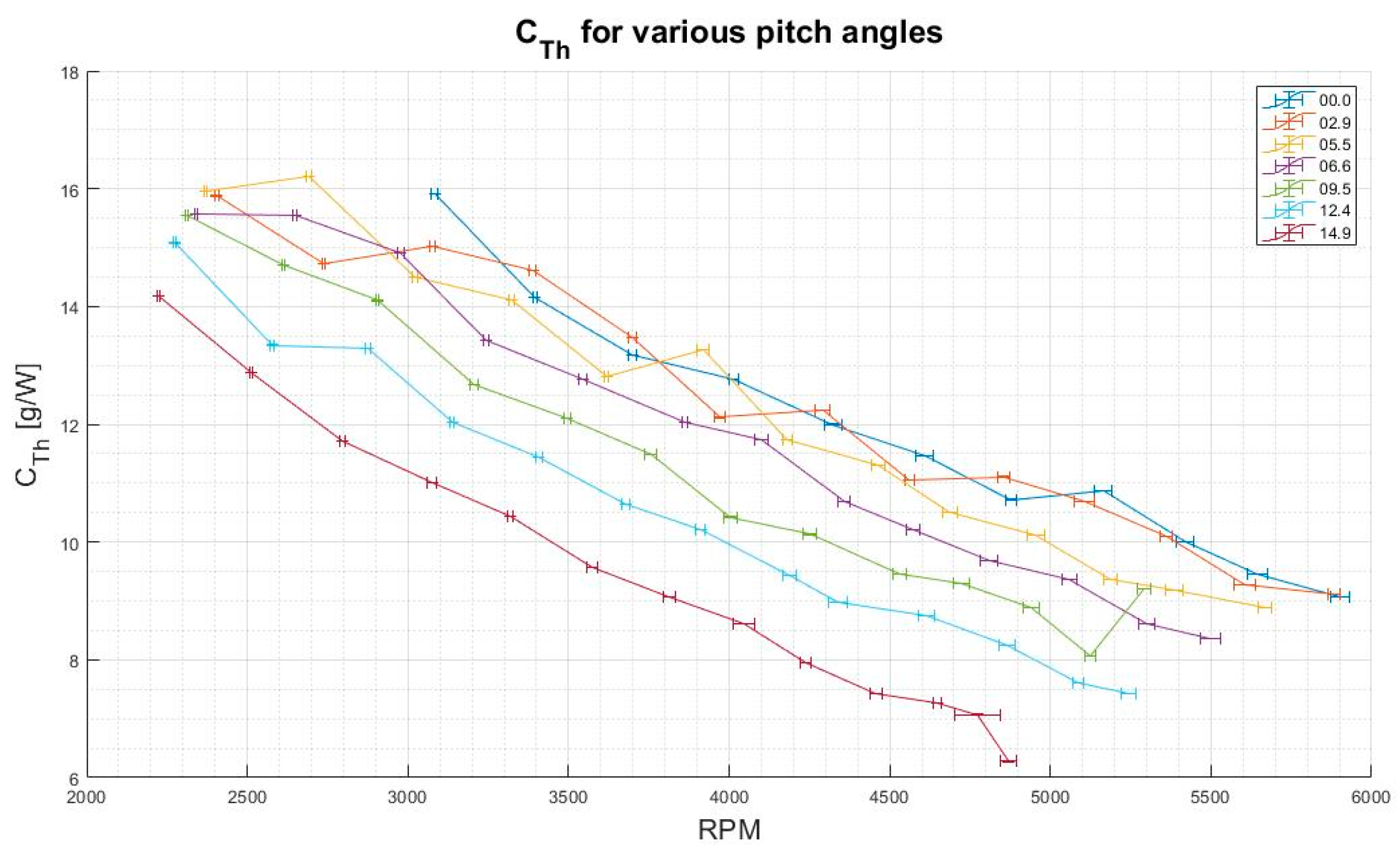
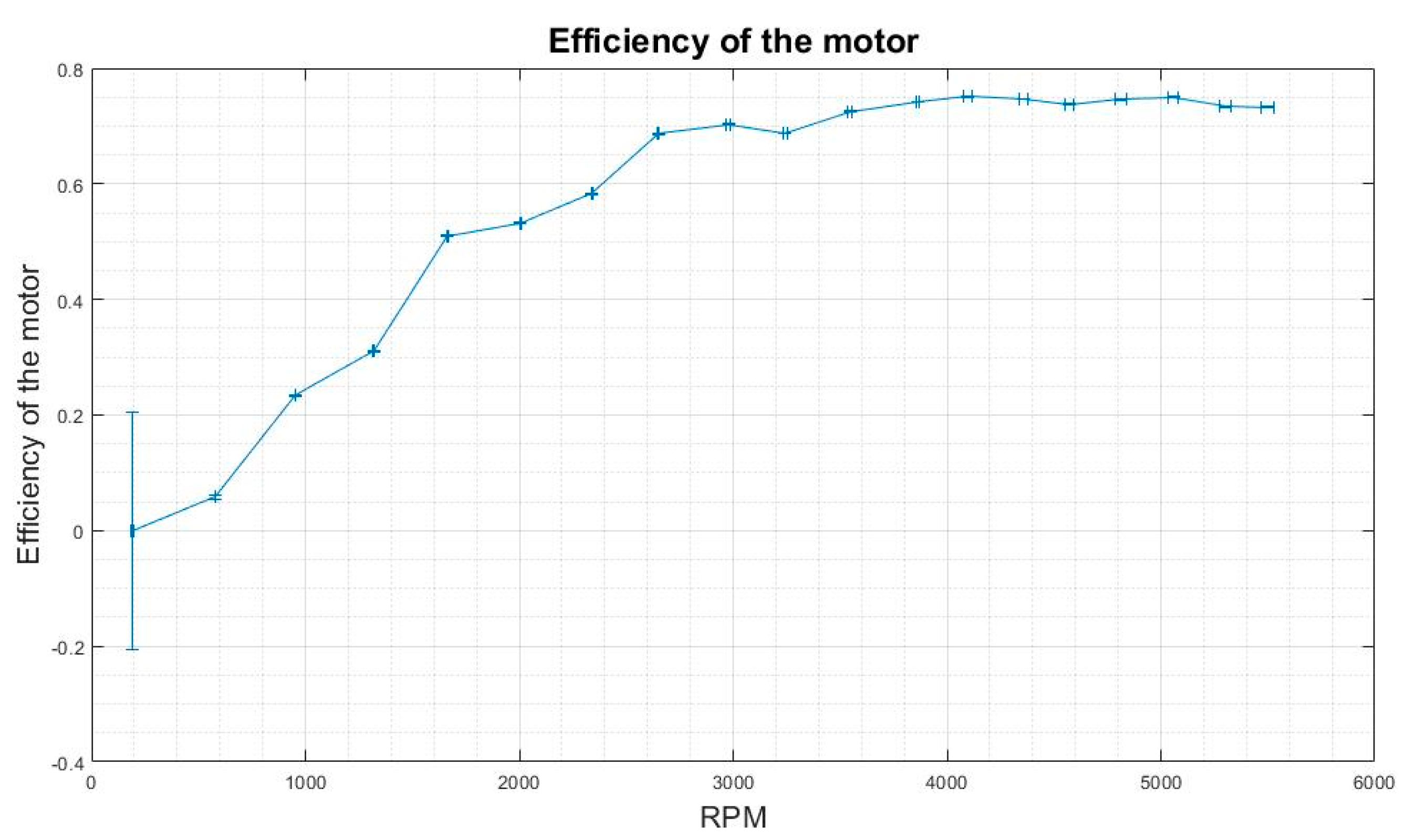
3.2. Coefficient of Thrust during Hover and Motor Efficiency Analysis

The C T H coefficient represents the mass value that can be lifted with 1 W of power drawn from the source. It strongly depends on the components used in the drive system, in particular, the motor and propeller. The graph in Figure 8 depicts a change of this coefficient with respect to change of propeller rotational speed. It shows that the highest C T h values are achieved for the lowest RPMs. Additionally, a decrease in the coefficient can be observed while the pitch angle increases. One can notice that the maximal C T h values near 16 g/W were obtained for much higher rotational speeds than in the case of increased pitch values. Moreover, one must bear in mind that the maximal thrust illustrated in Figure 5 requires more energy consumption and is not unequivocal to lifting efficiency with the use of the minimal energy stored in batteries. The final efficiency of the whole system depends on motor efficiency as well.
Figure 9 shows efficiency of the electric motor ( η m ) versus its rotational speed. It is noticeable that the engine works with the efficiency above 80% only at the rotational speed of about 2700 RPM and higher. Working at lower efficiency is inefficient and leads to energy losses, which results in reduced working time.

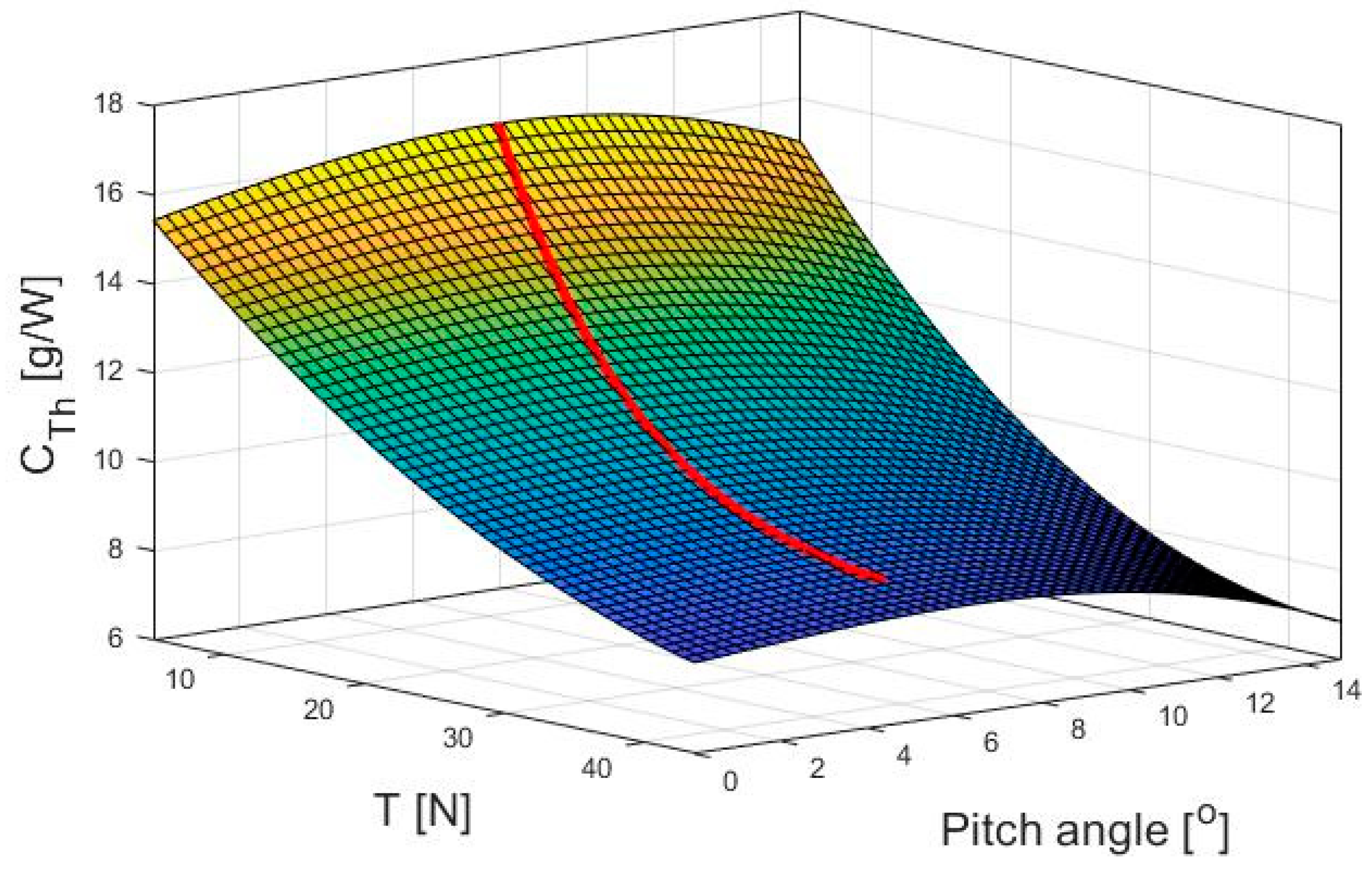
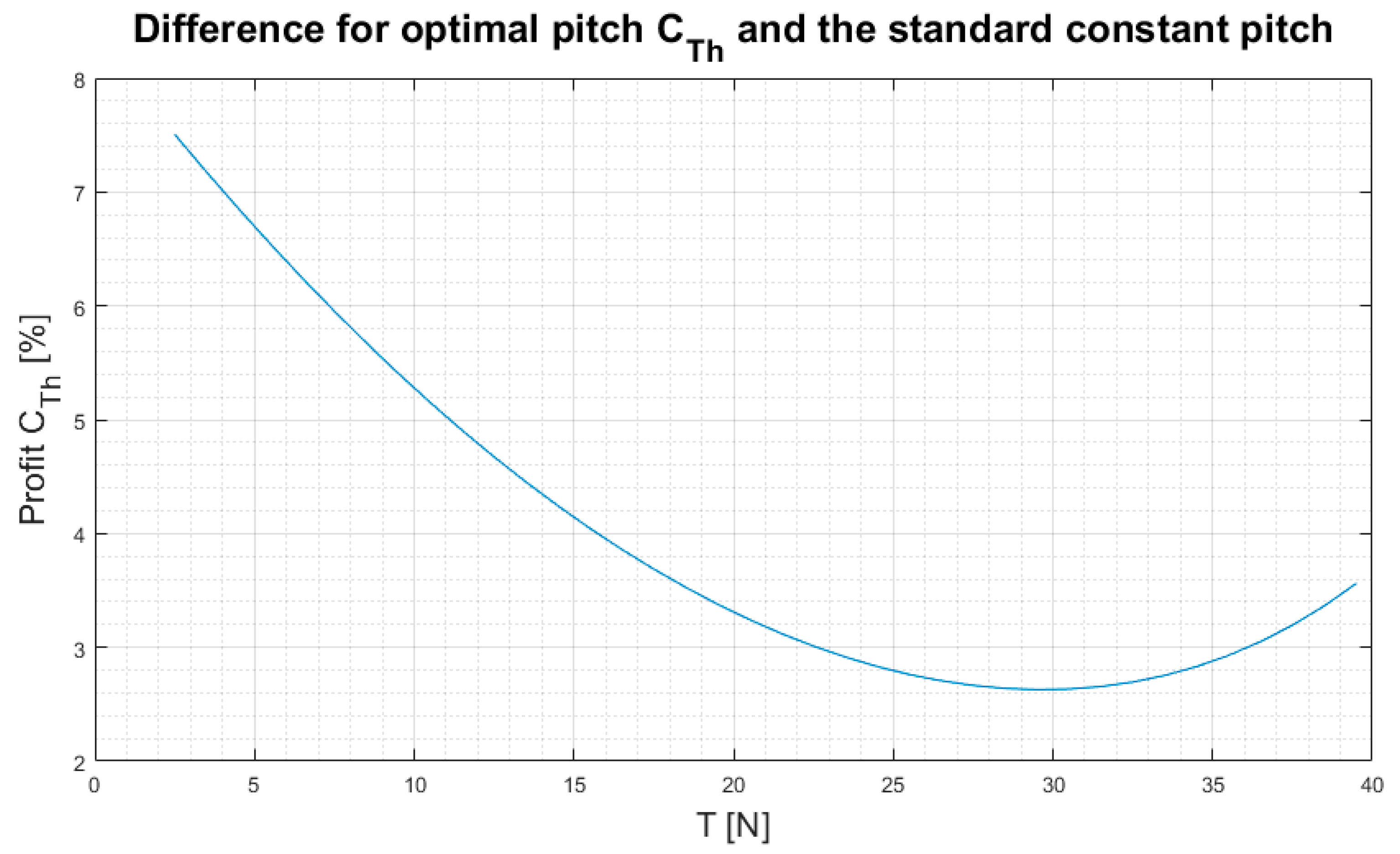
3.3. Recommendation towards a Pitch Control System Application

The main goal of the study was to determine possible pitch control algorithms to operate the UAV in the most efficient way. It was decided to focus on the best way to use the energy of batteries to perform missions depending on the mass of the package and UAV. On the basis of the selected goal of the mission, an appropriate control algorithm can then be used. The UAV control unit can determinate the needed thrust during flight and set a pitch angle to achieve the maximal range of operation under actual conditions.
The main purpose of the propulsion system is to provide an appropriate amount of thrust, and thus we intended to find the least energy-consuming propeller setup. The C T h coefficient was chosen as the best indicator of efficiency. Based on the collected data, the following mathematical model was obtained:
C T h = p 00   +   p 10 T   +   p 01 θ   +   p 20 T 2   +   p 11 T θ   +   p 02 θ 2   +   p 21 T 2 θ   + p 12 T θ 2   +   p 03 θ 3
The parametric identification of the proposed model was performed. The identification method was based on minimalizing the root mean square error (RMSE). Below, in Table 2, we present the results obtained with the RMSE: 0.9712.
To provide a method for setting the optimum pitch angle for the specific thrust maximum of C T h , a third-degree polynomial model with a set of coefficients was derived. The model which describes a value of the pitch angle to achieve the maximal C T h was determined and formulated as follows:
θ = c 1 T 3 + c 2 T 2 + c 3 T + c 4
For the propeller under testing, values of coefficients are presented in Table 3.
The graph depicted in Figure 10 shows an obtained model based on the collected data, where the C T H coefficient is represented versus the thrust and pitch angle. Then, a red curve on the graph was drawn to show the maximal C T H coefficient that can be obtained for a specific lift force with the best pitch angle setting.
In the graph (Figure 11), the red curve of Figure 10 is shown for two variables. It can be seen that in order to achieve the optimum pitch angle, i.e., when the C T h coefficient reaches the highest value, the pitch for a specific lifting force should be adjusted. A control algorithm based on pitch regulation in the given range can be applied to control thrust and energy consumption, for example, when the drone is to carry packages of different weight.
The graph in Figure 12 shows two curves: the red one represents the C T h obtained for the constant pitch of the original propeller before modifications described in Section 2, and the blue one represents the pitch changed according to the curve shown in Figure 11 for the modified propeller. It can be observed that the C T h obtained for the changed pitch is superior to the one obtained with the propeller of the fixed pitch.
Measurements for the fixed pitch propeller were conducted after modification and installation of the pitch change mechanism. A constant blade pitch-as manufactured-as achieved by locking the mechanism in position 0°. Although the propeller work will not be the same as before, it was cut because the diameter changes slightly. Nevertheless, the goal is to show the tendency, not the exact characteristics, of a particular propeller.
In Figure 13, a graph of C T h coefficient improvement while using a variable pitch compared to the fixed pitch is shown. One can notice that coefficient of thrust during hover showed an increase of 2.6% up to 7.5% for various pitch angles with respect to the original fixed propeller. The highest profit can be obtained at a low trust demand.

4. Discussion and Conclusions

Currently, fixed propellers are used widely for standard UAVs. This paper presents extensive investigations for one commercially available popular propeller, including modification of its geometry, in particular, to change the pitch angle of propeller blades.
One of the congruous works is an analysis of a helicopter propeller intended for flight to Mars [30]. The authors performed a similar analysis to that described in this article to select propeller parameters for difficult Martian flight conditions. They used the specific coefficient FM (figure of merit) to describe propeller efficiency to the pitch angle, but this coefficient does not include a power loss in the motor, in contrast to C T H . We believe that the C T h coefficient is better to analyze the optimal pitch angle. The plotted characteristics depict an efficiency index in the C T / C P ordinates depending on the blade angle of attack. It is shown that there is an optimal blade pitch angle that yields the highest thrust-to-drag ratio. Due to the constant mass of the unit and the maximal allowable drag moment generated by the propeller, optimization of hovering efficiency by changing the propeller pitch was not analyzed.
Similar mechanisms were tested in order to check a mathematical model of the rotor with a symmetrical airfoil and not twisted blades [36]. The data show no correlation with the determination of thrust. It should also be added that the authors, while building their mathematical model, focused on optimization of the propeller in terms of drag torque. The mathematical model derived in [36] describes a propeller with a pre-set factory pitch angle and focuses on flight optimization to make the most effective use of energy supplied to the propulsion system, i.e., to obtain the maximal possible C T H , which is important in UAV units. A comparison of the results with those obtained in the conducted experiment indicates that trends are the same for the majority of the characteristics. The results of both investigations are equal as regards to the order of magnitude, which confirms the tested principle and proves the correctness of the experiments.
One can find partial characteristics of a similar propeller with the same engine on the website of the engine manufacturer. However, the experiment shows that the behavior of the engine changes with the type of power source. The differences arise when the voltage of the power source is not constant, especially for batteries where voltage decreases with an increasing current. It can be observed in the characteristics of the C T h coefficient, which are underrated in the manufacturer’s data. As another propeller with a smaller nominal stroke of 16 × 5.4 was used, that can be a cause of the differences. However, the exact propeller specification is not provided.
Compared to the analyzes carried out in the cited references, a significant difference consists of the method of analyzing the C T h coefficient within the obtained thrust and blade pitch angle. A broad range of measurements of rotational speeds allowed us to conduct a thorough analysis of the overhang propeller efficiency and draw the following conclusions:
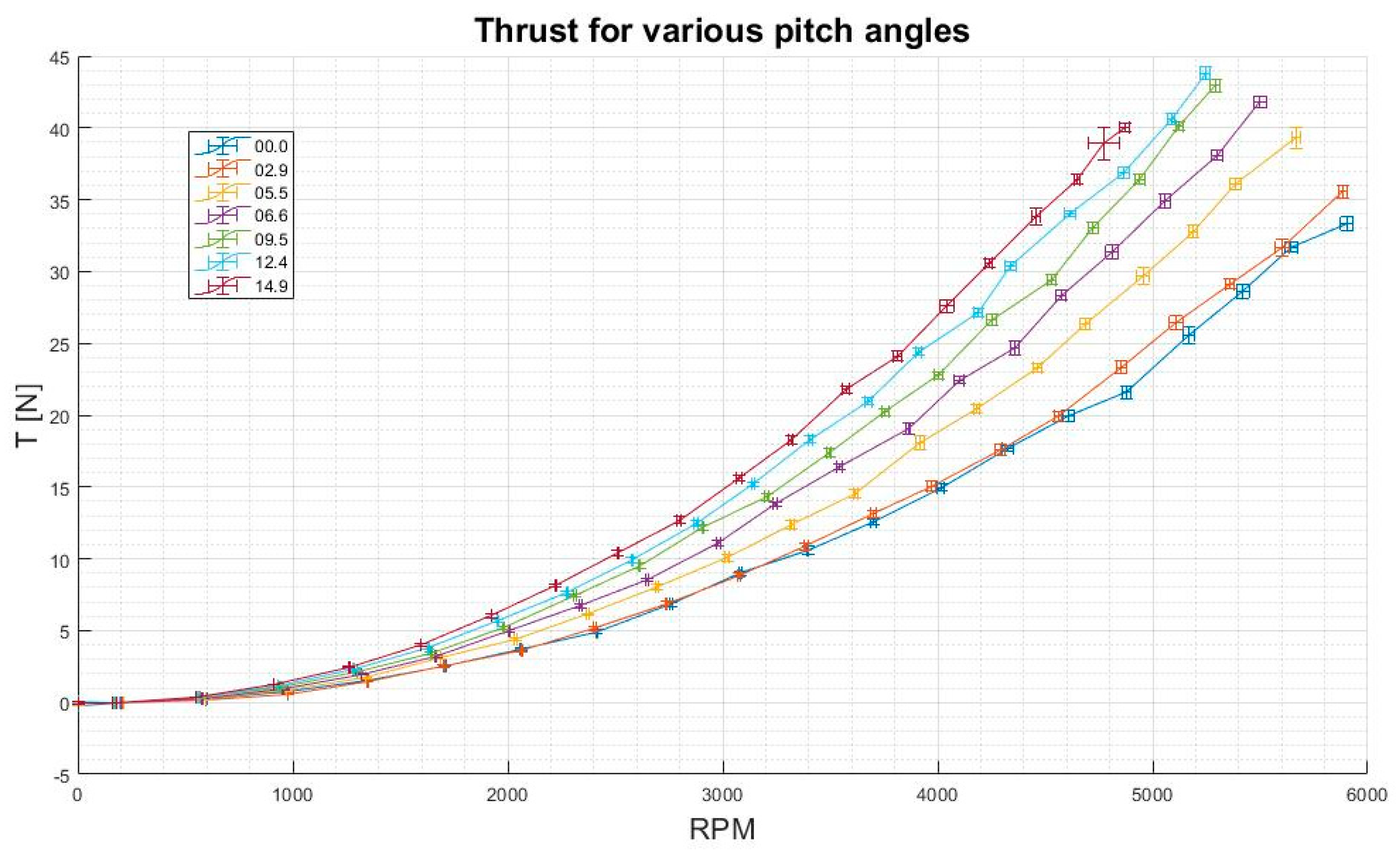
  • Based on the dependence showed in Figure 5, it is indicated that the temporary load capacity can be significantly increased by changing the pitch angle of blades. The increase in thrust measured was 31% for 12.5°.
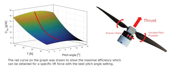
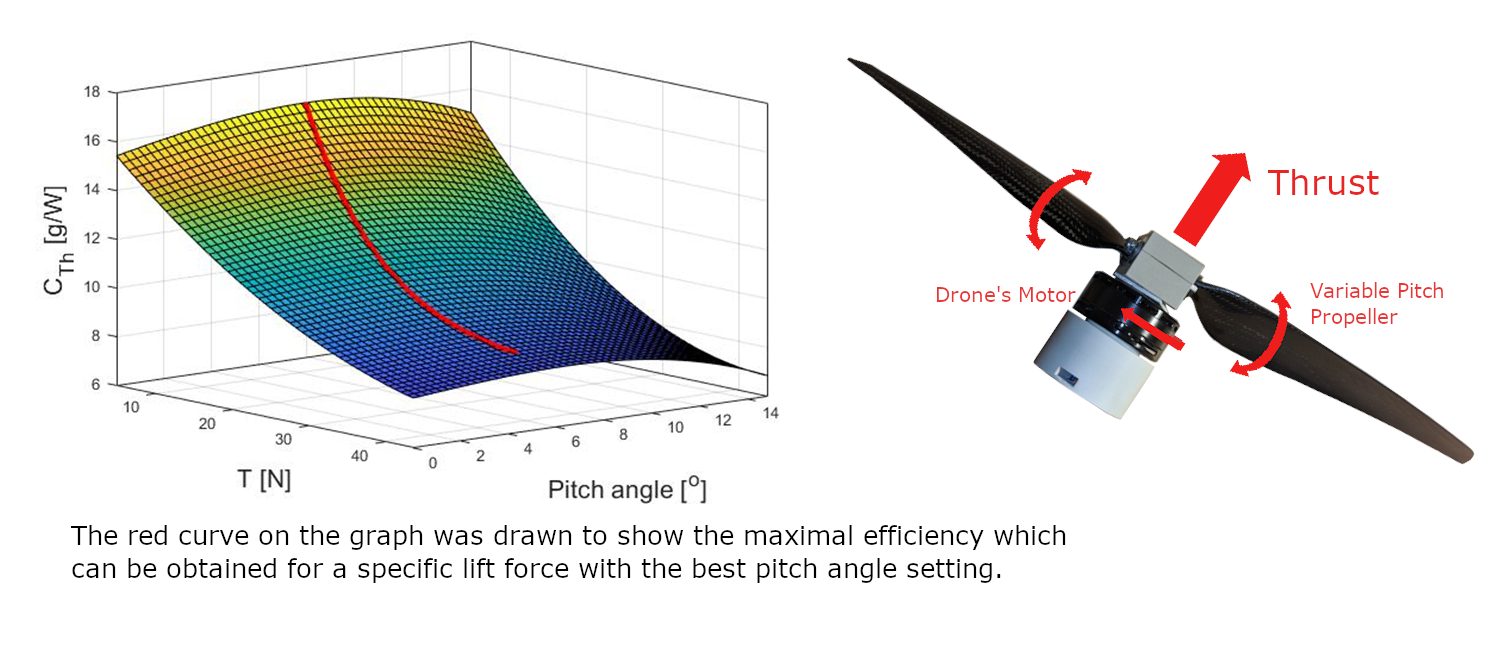
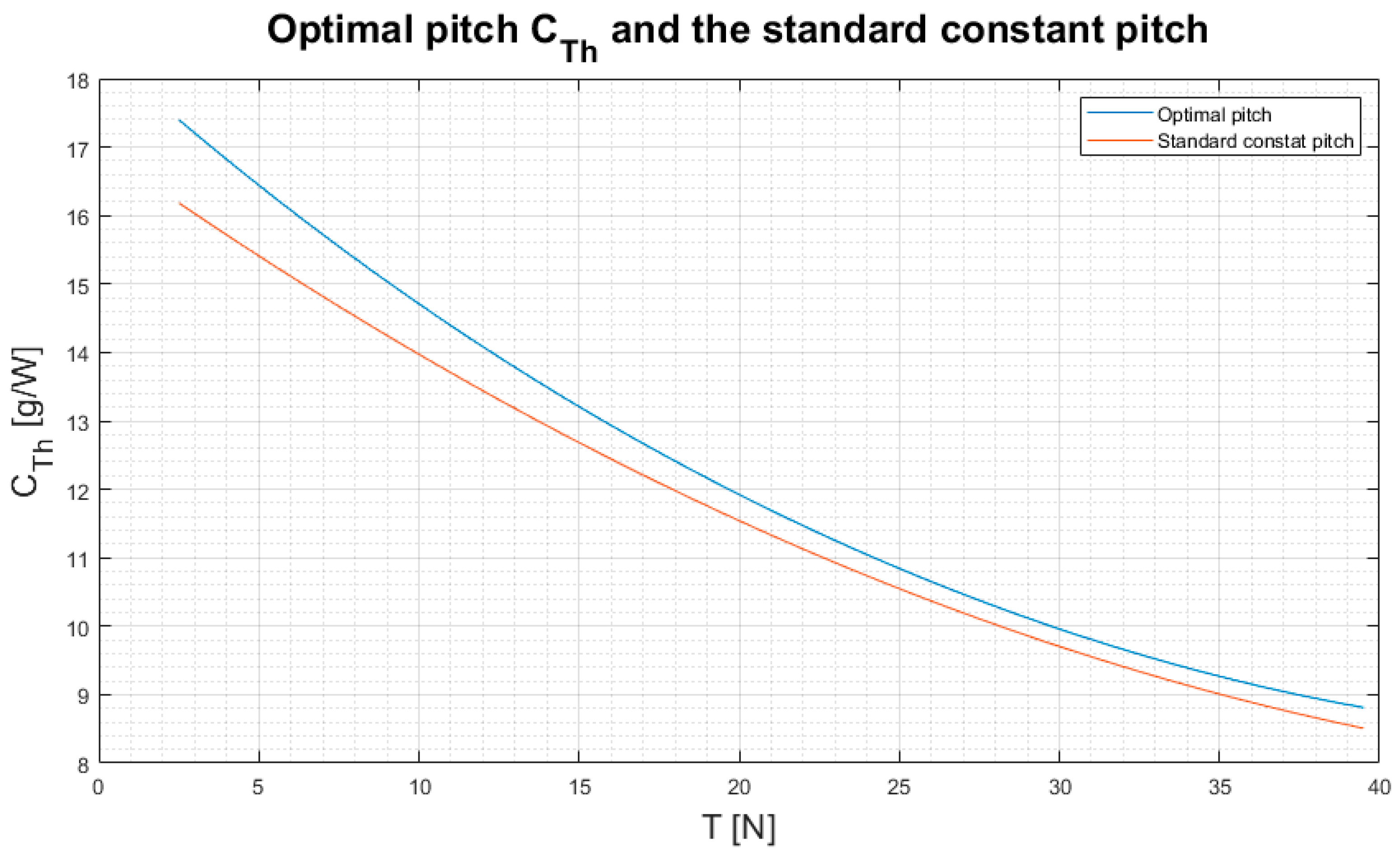
  • Another benefit of using a variable pitch propeller is an ability to set the propeller pitch angle according to the needed thrust. We have shown that thanks to our method, efficiency of the flight in hover can be improved from 2.6% up to 7.5% depending on the needed thrust.
  • The presented mathematical model can be used for similar propellers in a wide range of rotational speeds inherent to UAV motors. There is one optimal blade pitch angle that allows hovering with the least energy consumption for a particular thrust that is required for UAV hovering.
To summarize, energy consumption and lifting capacity are key parameters for UAVs to carry out transport missions. Therefore, it is possible to improve the performance of these flying units by using a mechanism for changing the pitch of propeller blades to match the current flight and machine conditions. The equation to calculate the optimal pitch for the rotor provided in this article can be easily used to achieve the best efficiency of the flying unit.

Author Contributions

Conceptualization, M.P. and R.K.; methodology, M.P. and R.K.; software, M.P. and R.K.; validation, D.O.; formal analysis, R.K. and M.P.; investigation, R.K. and M.P.; resources, K.K. and R.K.; data curation, M.P. and R.K.; writing—original draft preparation, R.K., M.P., K.K. and D.O.; writing—review and editing, D.O.; visualization, M.P.; supervision, D.O.; project administration, M.P. and R.K.; funding acquisition, K.K. and D.O. All authors have read and agreed to the published version of the manuscript.

Funding

This research received no external funding. It was funded by the Institute of Machine Tools, Production Engineering, the Institute of Turbomachinery and the Lodz University of Technology.

Acknowledgments

We would like to thank Malgorzata Jozwik for her significant linguistic help during the preparation of the manuscript.

Conflicts of Interest

The authors declare no conflict of interest.

Nomenclature

Symbol/AbbreviationUnitsDescription
CT-Coefficient of thrust
CP-Coefficient of power
CThg/WCoefficient of thrust during hover
DmPropeller diameter
gm/s2Acceleration due to gravity
IACurrent
QN·mRotational torque
n, rpmrev/minRotation per minute
PmWMechanical power
PeWElectrical power
RmRotor blade radius
TNThrust
UVVoltage
Uηm, UCT, UP, UCTh Uncertainty of the corresponding measurement
αdegAngle of attack
ηm-Efficiency of the motor
ρ kg/m3Air density
θdegBlade pitch angle
Φ degInflow angle
Ω rad/sRotor angular velocity (rad/sec)
ESC Electric speed controller
VTOL Vertical Takeoff Landing
UAV Unmanned Aerial Vehicle

References

  1. Gordon, M.; Kondor, S.; Corban, E.; Schrage, D. Rotorcraft aerial robot challenges and solutions. In Proceedings of the Digital Avionics System Conference, Fort Worth, TX, USA, 25–28 October 1993; pp. 298–305. [Google Scholar]
  2. Park, D.; Lee, Y.; Cho, T.; Kim, C. Design and performance evaluation of propeller for solar-powered high-altitude long-endurance unmanned aerial vehicle. Int. J. Aerosp. Eng. 2018, 2018, 1–23. [Google Scholar] [CrossRef]
  3. Torabbeigi, M.; Lim, G.J.; Kim, S.J. Drone Delivery Scheduling Optimization Considering Payload-induced Battery Consumption Rates. J. Intell. Robot. Syst. 2020, 97, 471–487. [Google Scholar] [CrossRef]
  4. Oh, T.H. Conceptual design of small unmanned aerial vehicle with proton exchange membrane fuel cell system for long endurance mission. Energy Convers. Manag. 2018, 176, 349–356. [Google Scholar] [CrossRef]
  5. Sun, S.; Visser, C. Aerodynamic Model Identification of a Quadrotor Subjected to Rotor Failures in the High-Speed Flight Regime. IEEE Robot. Autom. Lett. 2019, 4, 3868–3875. [Google Scholar] [CrossRef]
  6. Hassanalian, M.; Abdelkef, A. Classifications, applications, and design challenges of drones: A review. Prog. Aerosp. Sci. 2017, 91, 99–131. [Google Scholar] [CrossRef]
  7. Horla, D.; Cieślak, J. On Obtaining Energy-Optimal Trajectories for Landing of UAVs. Energies 2020, 13, 2062. [Google Scholar] [CrossRef] [Green Version]
  8. Boukoberine, M.N.; Zhou, Z.; Benbouzid, M. A critical review on unmanned aerial vehicles power supply and energy management: Solutions, strategies, and prospects. Appl. Energy 2019, 255, 113823. [Google Scholar] [CrossRef]
  9. Chaturvedi, S.K.; Sekhar, R.; Banerjee, S.; Kamal, H. Comparative Review Study of Military and Civilian Unmanned Aerial Vehicles (UAVs). INCAS Bull. 2019, 11, 183–198. [Google Scholar] [CrossRef]
  10. Chan, K.I. Generalized Aerodynamic Optimization of Hovering Coaxial Rotor Blades. J. Am. Helicopter Soc. 2019, 64, 1–13. [Google Scholar] [CrossRef]
  11. Kirschstein, T. Comparison of energy demands of drone-based and ground-based parcel delivery services. Transp. Res. Part D Transp. Environ. 2020, 78, 102209. [Google Scholar] [CrossRef]
  12. Mohiuddin, A.; Taha, T.; Zweiri, Y.; Gan, D. UAV Payload Transportation via RTDP Based Optimized Velocity Profiles. Energies 2019, 12, 3049. [Google Scholar] [CrossRef] [Green Version]
  13. Scott, J.E.; Scott, C.H. Drone Delivery Models for Healthcare. In Proceedings of the 50th Hawaii International Conference on System Sciences, Waikoloa, HI, USA, 4–7 January 2017; pp. 1–8. [Google Scholar]
  14. Kellermann, R.; Biehle, T.; Fischer, L. Drones for parcel and passenger transportation: A literature review. Transp. Res. Interdiscip. Perspect. 2020, 4, 100088. [Google Scholar] [CrossRef]
  15. Zaludin, Z.; Harituddin, A.S.M. Challenges and Trends of Changing from Hover to Forward Flight for a Converted Hybrid Fixed Wing VTOL UAS from Automatic Flight Control System Perspective. In Proceedings of the 2019 IEEE 9th International Conference on System Engineering and Technology (ICSET), Shah Alam, Malaysia, 7 October 2019; pp. 247–252. [Google Scholar]
  16. Wu, Y.; Du, X.; Duivenvoorden, R.; Kelly, J. The Phoenix Drone: An Open-Source Dual-Rotor Tail-Sitter Platform for Research and Education. In Proceedings of the IEEE International Conference on Robotics and Automation (ICRA’19), Montreal, QC, Canada, 20–24 May 2019; pp. 5330–5336. [Google Scholar]
  17. Wang, W.; Zhu, J.; Kuang, M.; Yuan, X.; Tang, Y.; Lai, Y.; Chen, L.; Yang, Y. Design and hovering control of a twin rotor tail-sitter UAV. Sci. China Inf. Sci. 2019, 62, 194202. [Google Scholar] [CrossRef] [Green Version]
  18. Phillips, B.P.; Hrishikeshavan, V.; Rand, O.; Chopra, I. Design and Development of a Scaled Quadrotor Biplane with Variable Pitch Proprotors for Rapid Payload Delivery. In Proceedings of the American Helicopter Society 72nd Annual Forum, West Palm Beach, FL, USA, 17–19 May 2016; pp. 302–315. [Google Scholar]
  19. Liu, N.; Cai, Z.; Zhao, J.; Wang, Y. Predictor-based model reference adaptive roll and yaw control of a quad-tiltrotor UAV. Chin. J. Aeronaut. 2019, 33, 282–295. [Google Scholar] [CrossRef]
  20. Chen, C.; Zhang, J.; Zhang, D.; Shen, L. Control and flight test of a tilt-rotor unmanned aerial vehicle. Int. J. Adv. Robot. Syst. 2017, 14, 1–12. [Google Scholar] [CrossRef]
  21. Cetinsoy, E.; Dikyar, S.; Hancer, C.; Oner, K.T.; Sirimoglu, E.; Unel, M.; Aksit, M. Design and construction of a novel quad tilt-wing UAV. Mechatronics 2012, 22, 723–745. [Google Scholar] [CrossRef]
  22. Brandt, J.B.; Selig, M.S. Propeller performance data at low Reynolds numbers. In Proceedings of the 49th AIAA Aerospace Sciences Meeting, Orlando, FL, USA, 4–7 January 2011; p. 1255. [Google Scholar]
  23. Stajuda, M.; Karczewski, M.; Obidowski, D.; Jóźwik, K. Development of a CFD model for propeller simulation. Mech. Mech. Eng. 2016, 20, 579–593. [Google Scholar]
  24. Kotarski, D.; Krznar, M.; Piljek, P.; Simunic, N. Experimental Identification and Characterization of Multirotor UAV Propulsion. In Proceedings of the 2nd International Conference on Measurement Instrumentation and Electronics, Prague, Czech Republic, 9–11 June 2017; pp. 16–24. [Google Scholar]
  25. OL, M.; Zeune, C.; Logan, M. Analytical—Experimental Comparison for Small Electric Unmanned Air Vehicle Propellers. In Proceedings of the 26th AIAA Applied Aerodynamics Conference, Honolulu, HI, USA, 18–21 August 2008; p. 7345. [Google Scholar]
  26. Merchant, M.; Miller, L.S. Propeller performance measurement for low Reynolds number UAV applications. In Proceedings of the 44th AIAA Aerospace Sciences Meeting and Exhibit, Reno, NV, USA, 9–12 January 2006; p. 1127. [Google Scholar]
  27. Ning, Z. Experimental Investigations on the Aerodynamic and Aeroacoustic Characteristics of Small UAS Propellers. Ph.D. Thesis, Iowa State University Capstones, Ames, IA, USA, 2018. [Google Scholar]
  28. Molter, C.; Cheng, P. Propeller performance calculation for multicopter aircraft at forward flight conditions and validation with wind tunnel measurements. In Proceedings of the International Micro Air Vehicle Conference and Flight Competition 2017, Toulouse, France, 18–21 September 2017; pp. 307–315. [Google Scholar]
  29. Lee, B.E.; Byun, Y.S.; Kim, J.; Kang, B.S. Experimental hover performance evaluation on a small-scale rotor using a rotor test stand. J. Mech. Sci. Technol. 2011, 25, 1449. [Google Scholar] [CrossRef]
  30. Shrestha, R.; Benedict, M.; Hrishikeshavan, V.; Chopra, I. Hover performance of a small-scale helicopter rotor for flying on mars. J. Aircr. 2016, 53, 1160–1167. [Google Scholar] [CrossRef]
  31. Panayotov, F.; Dobrev, I.; Massouh, F.; Todorov, M. Experimental study of a helicopter rotor model in hover. In Proceedings of the 10th International Scientific Conference on Aeronautics, Automotive and Railway Engineering and Technologies, Sozopol, Bulgaria, 15–17 September 2018; p. 01002. [Google Scholar]
  32. Cohen, R.; Miculescu, S.; Reilley, K.K.; Pakmehr, M.; Feron, E. Online Performance Optimization of a DC Motor Driving a Variable Pitch Propeller. Available online: https://arxiv.org/abs/1310.0133 (accessed on 5 August 2020).
  33. Manchiin, A.; Lafta, W.M.; Dao, D.V. Smart variable pitch propeller system for unmanned aerial vehicles. Int. J. Sci. Eng. Res. 2018, 7, 5238–5241. [Google Scholar]
  34. Abhishek, R.D.; Duhoon, A.; Kothari, M.; Kadukar, S.; Rane, L.; Suryavanshi, G. Design, Development, and Closed-loop Flight-Testing of a Single Power Plant Variable Pitch Quadrotor Unmanned Air Vehicle. In Proceedings of the 73rd American Helicopter Society Annual Forum 2017, Fort Worth, TX, USA, 9–11 May 2017; pp. 205–218. [Google Scholar]
  35. Chipade, V.S.; Kothari, M.; Chaudhari, R.R. Systematic design methodology for development and flight testing of a variable pitch quadrotor biplane VTOL UAV for payload delivery. Mechatronics 2018, 55, 94–114. [Google Scholar] [CrossRef] [Green Version]
  36. Arellano-Quintana, V.M.; Merchán-Cruz, E.A.; Franchi, A. A novel experimental model and a drag-optimal allocation method for variable-pitch propellers in multirotors. IEEE Access 2018, 6, 68155–68168. [Google Scholar] [CrossRef]
Figure 1. Scheme of the measuring station for testing forces and moments for different stroke settings: 1-Computer with Labview software; 2-Motor controller HOLYBRO ESC TEKKO32 35A; 3-Variable pitch propeller controller; 4-Measuring card ATI FTIFPS1 SI-40-2; 5–6-axis force and torque sensor F/T Sensor Mini40; 6-Servo drive of the variable pitch propeller mechanism; 7-Motor Mad 5008 from Mad Components and 8-Variable pitch propeller mechanism.
Energies 13 05264 g001
Figure 2. Connection diagram on the propeller force and moments measuring station for various pitch settings.
Energies 13 05264 g002
Figure 3. Unmodified propeller (16 × 6).
Energies 13 05264 g003
Figure 4. Variable pitch propeller with the engine.
Energies 13 05264 g004
Figure 5. Thrust for various pitch angles.
Energies 13 05264 g005
Figure 6. Coefficient of power (CP) for various pitch angles.
Energies 13 05264 g006
Figure 7. Coefficient of thrust (CT) for various pitch angles.
Energies 13 05264 g007
Figure 8. Coefficient of thrust during hover (CTh) for various pitch angles.
Energies 13 05264 g008
Figure 9. Efficiency of the motor.
Energies 13 05264 g009
Figure 10. CTh in for various pitches at specific thrust.
Energies 13 05264 g010
Figure 11. Optimal pitch for various thrusts.
Energies 13 05264 g011
Figure 12. Comparison of CTh for optimal pitch and standard constant pitch.
Energies 13 05264 g012
Figure 13. Difference in CTh for optimal pitch and standard constant pitch.
Energies 13 05264 g013
Table 1. Maximal thrust for various pitch angles.
Blade Angle (Degree)Maximal Thrust (N)Maximal Rotational Speed (rev/min)
0.033.345902
2.935.555883
5.539.305668
6.641.795498
9.542.955290
12.443.785244
14.940.064869
Table 2. Identification of coefficients of the model.
Coefficients p 00   p 10   p 20   p 11   p 02   p 21   p 12   p 03  
Value 16.99 0.3309 2.903 × 10 3 0.01114 0.00398 1.639 × 10 4 1.13 × 10 4 8.362 × 10 4
Table 3. Identification of coefficients of the model.
Coefficients c 1 c 2 c 3 c 4
Value 6.808 × 10 5 3.634 × 10 4 0.1669 8.725

