Abstract
An exhaust gas recirculation (EGR) valve position control system requires fast response without overshoot, but the low control frequency limits control bandwidth and results in poor position response. A novel EGR valve position control scheme is proposed to improve the position response at low control frequency. This is based on the feedforward controller, but the feedforward control loop is implemented without the position pattern generator or derivative. The proposed method estimates the acceleration command through the relationship between the position controller output, the speed command and the speed limiter, and compensates the cascaded proportional-proportional integral (P-PI) controller. In this method, many operations are not required and noise due to derivative is not generated. This method can improve the position response without much computation and derivative noise at the low control frequency. Experimental results are presented to verify the feasibility of the proposed position control algorithm.
1. Introduction
Environmental pollution by vehicle exhaust gas is an important issue in the world. In particular, nitrogen oxides (NOx) are strictly regulated by the EURO 6 standard for exhaust gas regulation [1,2]. The exhaust gas recirculation (EGR) valve is an automotive component that recirculates the exhaust gas to the engine to reduce NOx emission [3]. The recirculated exhaust gas lowers oxygen concentration and temperature of the engine cylinder, and NOx emission is also reduced [4]. The amount of the recirculated exhaust gas is determined by the position of the EGR valve [5]. If the valve is opened a lot, the amount of the gas is increased and the NOx emission is reduced. However, there is a trade-off relationship between NOx emission and fuel economy [6]. To meet the NOx emission standard and minimize the lowering of the fuel economy, the recirculated exhaust gas should be properly controlled through the EGR valve. Therefore, the EGR valve position control system needs a quick response because the required valve position constantly changes according to the driving situation of the vehicle. The EGR valve position is mechanically limited due to the structure of the valve [7]. Since the position overshoot can cause system failure, the position response without overshoot is also required.
Direct current (DC) motor and brushless direct current (BLDC) motor are commonly used as actuators for the EGR valve [8]. Therefore, the EGR valve position control system has the same structure as the position control system of the motor. The EGR valve position is proportional to the motor angular position measured by the Hall effect sensor inside the EGR valve [9]. The sensor is commonly used in automotive applications because it is low cost, contactless, and robust in the harsh environment of the engine. However, the Hall effect sensor has poor sensitivity, low accuracy, and is more susceptible to noise than a digital sensor, such as an optical encoder [10]. The electronic control unit (ECU) is a microcontroller that controls the parts of the automobile, and the EGR valve system is controlled by the engine ECU. Since the engine consists of many subsystems as well as the EGR valve system, a lot of computation is required for the operation of the engine [11]. The long computation time of the ECU makes it impossible for the EGR valve system to be controlled at a high frequency. As a result, the control bandwidth is limited by the low control frequency, and the EGR valve position control system cannot respond quickly without the position overshoot.
Many studies on the improvement in the position control algorithm have been published [12,13,14,15]. A feedforward control scheme using a time-based position pattern generator was proposed [12]. This scheme can control the position of all profiles to reach the required position without error. But if an error in the position pattern occurs, the position controller cannot compensate for the error. In addition, the process of making the position pattern is complex and requires more parameters in the system. In [15], a scheme consisting of a position controller and a current controller in series without a speed controller was proposed. The control bandwidth of the position controller, which is limited by the speed controller, can increase and improve the position response. But in this scheme, the speed cannot be controlled reliably because there is no speed controller and limiter. Gain tuning is difficult due to a large number of gains used in the position controller.
In this paper, a position control scheme using the feedforward controller that overcomes the disadvantages of the conventional position controller is proposed. The proposed controller is based on the cascaded proportional-proportional integral (P-PI) controller and compensates for the output of the feedforward controller using the relationship between the position controller output, the speed command, and the speed limiter. The position pattern generator that requires additional parameters of the system is not used. Therefore, gain tuning is not difficult because no extra gain is needed. To verify the feasibility of the proposed position control scheme, experimental results for the EGR valve position control system under various operating conditions are presented.
2. Conventional System and Position Control Methods
2.1. EGR Valve Position Control System
Figure 1 illustrates a block diagram of the EGR valve position control system using the DC motor as the actuator. The system consists of the EGR valve, the H-bridge circuit, and the position control system. In the position control system, the cascaded P-PI controller is mainly used and has a structure that connects the P-position controller and the PI-speed controller in series [16]. To obtain the motor angular speed ωm of the PI-speed controller, the speed estimation through the derivative of the motor angular position θm causes the noise by the derivative or the delay by the filter. In [17], the speed observer enables the speed estimation without problems of the derivative, and the speed observer is applied to obtain the motor angular speed in the system.
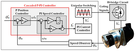
Figure 1.
Block diagram of the exhaust gas recirculation (EGR) valve position control system using the direct current (DC) motor.
A simplified block diagram of the position control system with the cascaded P-PI controller is shown in Figure 2. The transfer function of the system can be derived as Equation (1) and is equal to the second-order low pass filter (LPF) [16].
where θm* is the motor angular position command of the P-position controller, Kpp is the proportional gain of the P-position controller, and ωsc is the bandwidth of the PI-speed controller. ω0 and ζ are the natural frequency and the damping ratio of the second-order LPF, respectively. To suppress the position overshoot, ζ of the second-order LPF should be larger than 1, and Kpp is limited to ωsc/4. As a result, the position response at the low control frequency cannot be improved because the gain of the P-position controller is limited by the speed control bandwidth.
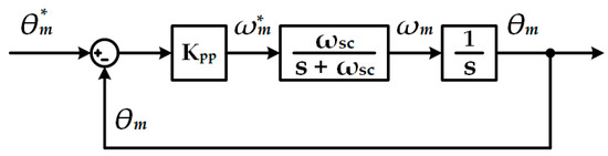
Figure 2.
The simplified block diagram of the cascaded proportional-proportional integral (P-PI) controller.
2.2. Feedforward Controller with a Position Pattern Generator
Figure 3 shows a block diagram of the cascaded P-PI controller with the time-based position pattern generator and the feedforward control loop [12]. The time-based profile created by the jerk pattern generator consists of the jerk needed to reach the position command. And the position trajectory generated by the integral of the jerk pattern becomes the position command of the cascaded P-PI controller. To improve the position response of the system, the velocity and acceleration patterns are compensated to the P-position controller and the PI-speed controller, respectively. The transfer function of the position control system is derived as follows:
where Jm.est and Kt.est are the estimated inertia and torque constant of the motor, respectively. Jm and Kt are the real inertia and torque constant of the motor, respectively. Kps and Kis are the proportional and integral gain of the PI-speed controller, respectively. If the estimated constants are equal to the real constants of the motor, the function is 1, and the actual position follows the position pattern completely. However, the error of parameters required for the jerk pattern generator causes position pattern error. The error is not compensated by the feedback controller and the feedforward control loop of the system. The process of generating the position pattern requires significant computation and is complicated. Therefore, the position control algorithm is not suitable for the EGR valve system.
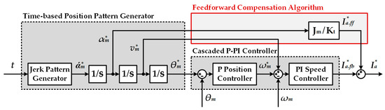
Figure 3.
The block diagram of the cascaded P-PI controller with the time-based position pattern generator and the feedforward control loop.
2.3. Acceleration Command Feedforward Controller
Figure 4a shows the acceleration command feedforward control loop of the PI-speed controller in the speed control system [13]. The velocity pattern created through the integral of the acceleration command is used as the speed command, and the acceleration command is compensated to the speed controller. However, in the position control system using the cascaded P-PI controller, the speed command is the position controller output, as shown in Figure 4b. The acceleration command generated through the derivative of the speed command is compensated to the speed controller. The transfer function of the position control system is derived as follows:
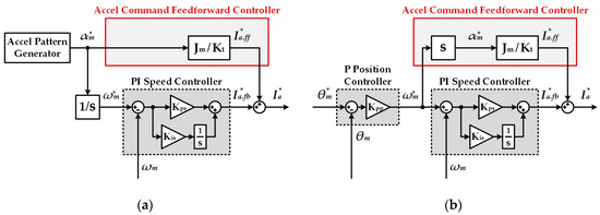
Figure 4.
The acceleration command feedforward control loop of the PI-speed controller: (a) in the speed control system; and (b) in the position control system using the cascaded P-PI controller.
If the estimated parameters are correct, the function is the first order LPF, and Kpp is the cutoff frequency. And the system has a fast response without the position overshoot because Kpp is not limited to ωsc/4. However, the acceleration command generated through the derivative of the speed command contains noise by the derivative, and the feedforward controller output also has noise. As a result, the motor’s torque ripple is caused by the feedforward controller, which degrades the performance and durability of the EGR valve.
3. Proposed Position Control System
3.1. Feedforward Controller Based on Speed Command
In the cascaded P-PI controller, the speed command is the position controller output and can be expressed as Equation (4). Therefore, the acceleration command is the same as the derivative of the position controller output and can be represented by Equation (5).
where ωm* is the motor angular speed command of the PI-speed controller, αm* is the motor angular acceleration command. The EGR valve position control system basically has a constant position command because the position command is received in steps from the host controller in the engine ECU, and the derivative of the position command is 0. From Equation (5), the acceleration command is derived as follows:
However, the speed limiter is used in the position control system because the motor angular speed is limited electrically and mechanically. In the cascaded P-PI controller, the speed limiter is located between the position controller and the speed controller, as shown in Figure 5.
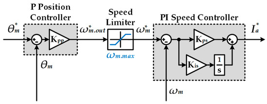
Figure 5.
The speed limiter of the cascaded P-PI controller.
Figure 6a shows the speed command in the position control loop through the cascaded P-PI controller. In the region I where the position controller output ω*m.out reaches the maximum speed of the speed limiter ωm.max, the speed command is replaced with the maximum speed from the positon controller output. Although the position controller output is changed by the speed limiter, the speed limiter is not considered in the speed controller. Thus, the position controller output is equal to the maximum speed in the speed controller. The relationship between the speed command and the position controller output can be represented by Equation (7), and the position command is derived as Equation (8).
In the position control loop, Figure 6b shows the position command from the speed controller perspective.
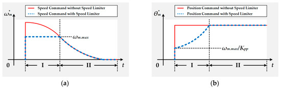
Figure 6.
The influence of the speed limiter in the position control loop: (a) the speed command; and (b) the position command.
From Equations (5) and (8), the acceleration command becomes 0 in the region Ⅰ. And the acceleration command is equal to Equation (6) in the region II where there is no influence by the speed limiter. Therefore, the acceleration command in all regions is arranged as follows:
3.2. Feedforward Controller Based on Position Command
The position response can be further improved by adding the feedforward controller based on the position command, as shown in Figure 7. The transfer function of the position control system, including the additional feedforward controller added, is derived as follows:
If the estimated constants are correct, the valve position always follows the position command, and the position response is faster.
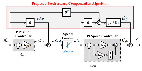
Figure 7.
The block diagram of the proposed feedforward compensation algorithm.
The feedforward control loop based on the position command is also affected by the derivative and speed limiter. In the region I, the changed position command of Equation (8) is applied to the loop compensated for the speed controller, and the output of the feedforward controller is derived as follows:
where αm is the motor angular acceleration. In region II, the acceleration command becomes 0 because it is the constant position command.
However, the loop compensated by the position controller is located before the speed limiter and is not affected by the limiter. The velocity command based on the position command, v*m.ff, becomes zero because the position command is constant in all regions. From Equations (9) and (11), the output of the proposed compensator, according to the region, is derived as follows:
In regions I and II, the motor angular acceleration and speed are compensated to the speed controller, respectively.
Figure 8 is a block diagram of the proposed EGR valve position control system, including the proposed compensation algorithm. The proposed compensator distinguishes the region by comparing the position controller output with the maximum speed of the speed limiter, and the output of the compensator, according to the region, is compensated to the speed controller. And the motor angular acceleration is required in the proposed compensator. The estimation using the derivative and filter generates noise or delay. Thus, the acceleration observer associated with the existing speed observer [17] is used in the proposed system [18]. The proposed position control system can improve the position response at the low control frequency without the influence of the derivative and the speed limiter.
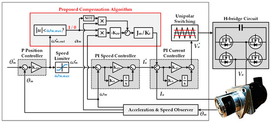
Figure 8.
The block diagram of the proposed EGR valve position control system, including the proposed compensation algorithm.
4. Experimental Results
The effectiveness of the proposed EGR valve position control system is demonstrated by several experiments in the experimental setup, as shown in Figure 9. The setup consisted of the test bench with the EGR valve and the control board. The EGR valve in the experiment is shown in Figure 10a, and the DC motor was used as the actuator. The specifications of the EGR valve are listed in Table 1. The EGR valve was controlled by the control board that included MCU TMS320F28335 of TI and the H-bridge circuit, as shown in Figure 10b. In the system, the switching frequency and the current control frequency was 1 kHz. The speed and position controller included in the cascaded P-PI controller was controlled at 100 Hz. And the control frequency of the proposed compensation algorithm was also 100 Hz.
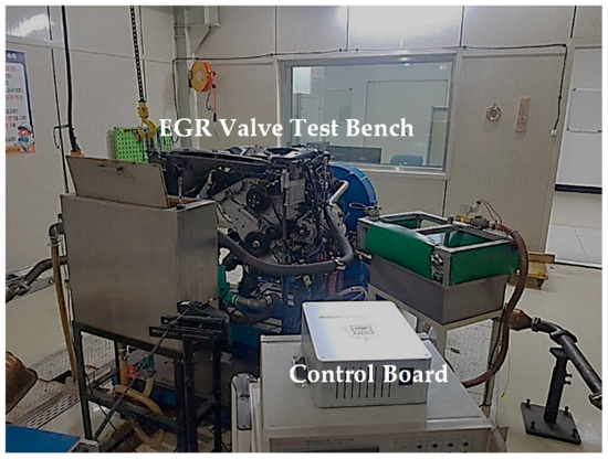
Figure 9.
The EGR valve test bench and control board.
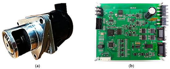
Figure 10.
The EGR valve position control system: (a) EGR valve; and (b) Control board.

Table 1.
Exhaust gas recirculation (EGR) valve specifications.
Figure 11 shows the armature current and fast fourier transform (FFT) analysis at steady state in the position response for the cascaded P-PI controller. Because the system was controlled by unipolar switching, the frequency of the current ripple was twice the switching frequency. Thus, current ripples of 2 kHz and 4 kHz were caused by the switching frequency and unipolar switching. Figure 12a shows the armature current and FFT analysis when the acceleration command through the derivative was compensated to the speed controller. Since the noise caused by the derivative was compensated for the current command controlled at the speed control frequency, a large current and torque ripple occurred at low frequencies of 100 Hz and 200 Hz. Low-frequency torque ripple causes problems, such as noise and vibration, in the EGR valve. However, when compensated by the proposed method instead of the derivative, the low-frequency current ripple was significantly reduced, as shown in Figure 12b. In addition, the noise and vibration of the EGR valve were also improved.
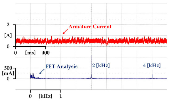
Figure 11.
The armature current and fast fourier transform (FFT) analysis at steady state in the position response for the cascaded P-PI controller.
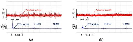
Figure 12.
The armature current and FFT analysis at steady state in the position response for the cascaded P-PI controller: (a) with the feedforward controller through the derivative; and (b) with the proposed compensation algorithm.
Figure 13 shows the position and speed response and the response flag in the position control system with the cascaded P-PI controller. The position command is the step input that changes from 10% to 90% when the maximum position of the EGR valve is 100%. The position response consisted of the position command and the EGR valve position, and the speed response included the speed command and the EGR valve speed. The response (t90%) flag became 1 when the EGR valve position was within +/−10% of the position command, and the response (t98%) flag was set to 1 when the position command was within +/−2%. Figure 13a shows the result when Kpp of the P-position controller was ωsc/4. Since the position response of the cascaded P-PI controller was the second order LPF as shown in (1), the maximum value of Kpp was ωsc/4 to avoid the underdamping, which causes the position overshoot. Thus, the system was controlled without the position overshoot, but the valve speed in the deceleration area did not fully follow the speed command due to the low control bandwidth, and the position response was also slow. In the case of Figure 13b, where the position controller gain was ωsc/2, the position response was faster as the position control bandwidth was increased. However, the valve speed could not follow the fast changing speed command in the deceleration area, and the position overshoot occurs because the speed control bandwidth was still low. Under the same experimental conditions as Figure 13b, the experimental results of the proposed position control system are shown in Figure 14. In the region I limited by the speed limiter, the valve acceleration was compensated to the speed controller. And the product of Kpp and the valve speed were compensated to the speed controller in the region II without the influence of the speed limiter. In particular, the fast response was obtained without the position overshoot because the valve speed completely followed the fast change of the speed command in the deceleration area.
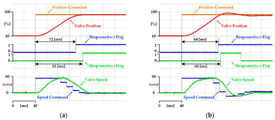
Figure 13.
The position and speed response and the response flag in the position control system with the cascaded P-PI controller when the position command changed from 10% to 90%: (a) when Kpp was ωsc/4; and (b) when Kpp was ωsc/2.
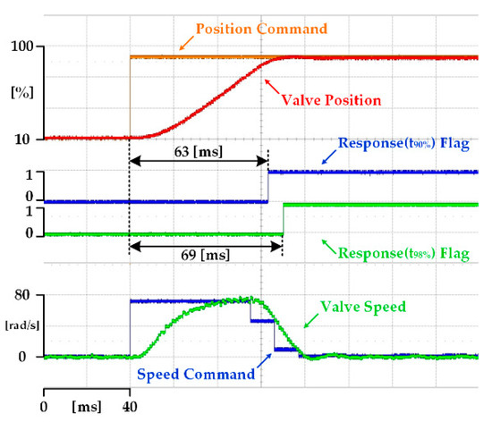
Figure 14.
The position and speed response and the response flag in the proposed position control system when the position command changed from 10% to 90%.
Since the position command of the EGR valve position control system has various positions, it is necessary to confirm the position response for the short distance as well as the long distance. Figure 15 shows the position and speed response and the response flag in the position control system with the cascaded P-PI controller. The position command was the step input that changed from 10% to 40%. Figure 15a,b shows the experimental results when the position controller gains were ωsc/4 and ωsc/2, respectively. Both experimental results showed the same trend as Figure 13. In Figure 15b, the position response was faster than the previous result, but the position overshoot occurred excessively, even though the position command was a short distance. Figure 16 shows the experimental results of the proposed position control system under the same experimental conditions as Figure 15b. The result of the proposed algorithm showed fast response without the position overshoot regardless of the distance of the position command.
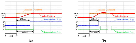
Figure 15.
The position and speed response and the response flag in the position control system with the cascaded P-PI controller when the position command changed from 10% to 40%: (a) when Kpp was ωsc/4; and (b) when Kpp was ωsc/2.
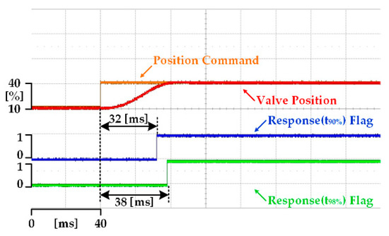
Figure 16.
The position and speed response and the response flag in the proposed position control system when the position command changed from 10% to 40%.
5. Conclusions
In this paper, the EGR valve position control system, including a novel compensator, was proposed. The proposed compensator estimates the acceleration command through the relationship between the position controller output and the speed command. The position command, according to the region divided by the speed limiter, is applied to the compensator. The output of the proposed compensator is compensated for the current command, and the position control has a fast response without overshoot. In the proposed algorithm, much computation is not required since the position pattern generator is not used. In addition, torque ripple does not occur because the acceleration command is not estimated through the derivative. The experimental results clarified the effectiveness of the proposed algorithm. Through the armature current and FFT analysis, it was confirmed that the current ripple of the proposed controller was smaller than the conventional feedforward controller. And the position response was improved not only in the long-distance command but also in the short-distance command.
Author Contributions
Conceptualization, J.-M.K.; formal analysis, visualization and writing—original draft preparation, H.-J.K.; validation, Y.-D.S.; writing—review and editing, Y.-D.S. and J.-M.K.; project administration, J.-M.K. All authors have read and agreed to the published version of the manuscript.
Funding
This research received no external funding.
Acknowledgments
This research was supported by the Basic Science Research Program through the National Research Foundation of Korea (NRF) funded by the Ministry of Education (NRF-2018R1D1A1B07048954).
Conflicts of Interest
The authors declare no conflict of interest.
References
- Kim, Y.; Park, T.; Jung, C.; Kim, C.H.; Kim, Y.W.; Lee, J.M. Hybrid nonlinear model predictive control of LNT and urealess SCR aftertreatment system. IEEE Trans. Control Syst. Technol. 2018, 27, 2305–2313. [Google Scholar] [CrossRef]
- Di Franco, C.; Elia, A.; Spagnolo, V.; Scamarcio, G.; Lugarà, P.M.; Ieva, E.; Cioffi, N.; Torsi, L.; Bruno, G.; Losurdo, M.; et al. Optical and electronic NOx sensors for applications in mechatronics. Sensors 2009, 9, 3337–3356. [Google Scholar] [CrossRef]
- Yoshioka, Y.; Kondo, H.; Tabata, Y.; Hatakenaka, H.; Nakada, K. Automatic control method of NO removal by a combination of ozone injection and exhaust gas recirculation. IEEE Trans. Ind. Appl. 2010, 46, 1166–1174. [Google Scholar] [CrossRef]
- Chen, P.; Wang, J. Observer-based estimation of air-fractions for a diesel engine coupled with aftertreatment systems. IEEE Trans. Control Syst. Technol. 2013, 21, 2239–2250. [Google Scholar] [CrossRef]
- Moos, R.; Reetmeyer, B.; Hürland, A.; Plog, C. Sensor for directly determining the exhaust gas recirculation rate—EGR sensor. Sens. Actuators B Chem. 2006, 119, 57–63. [Google Scholar] [CrossRef]
- Hiroyasu, T.; Nakayama, S.; Miki, M. Comparison study of SPEA2+, SPEA2, and NSGA-II in diesel engine emissions and fuel economy problem. In Proceedings of the IEEE Congress on Evolutionary Computation, Edinburgh, UK, 2–5 September 2005. [Google Scholar]
- Bhuiyan, H.; Lee, J.-H. Low cost position controller for exhaust gas recirculation valve system. Energies 2018, 11, 2171. [Google Scholar] [CrossRef]
- Gutfrind, C.; Dufour, L.; Liebart, V.; Vannier, J.C. An approach to the prototyping of an optimized limited stroke actuator to drive a low pressure exhaust gas recirculation valve. Sensors 2016, 16, 735. [Google Scholar] [CrossRef] [PubMed]
- Fleming, W.J. Overview of automotive sensors. IEEE Sens. J. 2001, 1, 296–308. [Google Scholar] [CrossRef]
- Manyala, J.O.; Fritz, T.; Atashbar, M.Z. Integration of triaxial hall-effect sensor technology for gear position sensing in commercial vehicle transmissions. IEEE Trans. Instrum. Meas. 2012, 61, 664–672. [Google Scholar] [CrossRef]
- Sun, J.; Kolmanovsky, J.; Cook, J.A.; Buckland, J.H. Modeling and control of automotive powertrain systems: A tutorial. In Proceedings of the American Control Conference, Portland, OR, USA, 8–10 June 2005. [Google Scholar]
- Ryu, H.-M.; Sul, S.-K. Position control for direct landing of elevator using time-based position pattern generation. In Proceedings of the IEEE Industry Applications Conference. 37th IAS Annual Meeting (Cat. No. 02CH37344), Pittsburgh, PA, USA, 13–18 October 2002. [Google Scholar]
- Sul, S.-K. 4.3 Speed regulator. In Control of Electric Machine Drive Systems; EI-Hawary, M.E., Ed.; Wily: Hoboken, NJ, USA, 2011; pp. 204–205. [Google Scholar]
- Heo, H.-J.; Son, Y.; Kim, J.-M. A trapezoidal velocity profile generator for position control using a feedback strategy. Energies 2019, 12, 1222. [Google Scholar] [CrossRef]
- Kim, J.-S.; Choi, M.-S.; Kan, S. The unified gain tuning approach to the PID position control with minimal overshoot, position stiffness, and robustness to load variance for linear machine drives in machine tool environment. In Proceedings of the Sixteenth Annual IEEE Applied Power Electronics Conference and Exposition (Cat. No. 01CH37181), Anaheim, CA, USA, 4–8 March 2001. [Google Scholar]
- Sul, S.-K. 4.4 Position regulator. In Control of Electric Machine Drive Systems; EI-Hawary, M.E., Ed.; Wily: Hoboken, NJ, USA, 2011; pp. 208–209. [Google Scholar]
- Lorenz, R.D.; Patten, K.W. High-resolution velocity estimation for all-digital, ac servo drives. IEEE Trans. Ind. Appl. 1991, 27, 701–705. [Google Scholar] [CrossRef]
- Schmidt, P.B.; Lorenz, R.D. Design principles and implementation of acceleration feedback to improve performance of dc drives. IEEE Trans. Ind. Appl. 1992, 28, 594–599. [Google Scholar] [CrossRef]


© 2020 by the authors. Licensee MDPI, Basel, Switzerland. This article is an open access article distributed under the terms and conditions of the Creative Commons Attribution (CC BY) license (http://creativecommons.org/licenses/by/4.0/).