Article

Research on Mechanism and Control of Floor Heave of Mining-Influenced Roadway in Top Coal Caving Working Face

1
School of Energy Engineering, Xi’an University of Science and Technology, Xi’an 710054, China
2
Key Laboratory of Western Mines and Hazard Prevention of China Ministry of Education, Xi’an 710054, China
3
State Grid Energy Hami Coal and Electricity Co., Ltd., Hami 839000, China
*
Author to whom correspondence should be addressed.
Energies 2020, 13(2), 381; https://doi.org/10.3390/en13020381
Submission received: 2 December 2019 / Revised: 4 January 2020 / Accepted: 10 January 2020 / Published: 13 January 2020
(This article belongs to the Special Issue Advanced Technologies for Energy Exploitation of Coals)

Abstract

:
The stability of the surrounding rock is the key problem regarding the normal use of coal mine roadways, and the floor heave of roadways is one of the key factors that can restrict high-yield and high-efficiency mining. Based on the 1305 auxiliary transportation roadway geological conditions in the Dananhu No. 1 Coal Mine, Xinjiang, the mechanism of roadway floor heave was studied by field geological investigation, theoretical analysis, and numerical simulation. We think that the surrounding rock of the roadway presents asymmetrical shrinkage under the original support condition, and it is the extrusion flow type floor heave. The bottom without support and influence of mining are the important causes of floor heave. Therefore, the optimal support scheme is proposed and verified. The results show that the maximum damage depth of the roadway floor is 3.2 m, and the damage depth of the floor of roadway ribs is 3.05 m. The floor heave was decreased from 735 mm to 268 mm, and the force of the rib bolts was reduced from 309 kN to 90 kN after using the optimization supporting scheme. This scheme effectively alleviated the “squeeze” effect of the two ribs on the soft rock floor, and the surrounding rock system achieves long-term stability after optimized support. This provides scientific guidance for field safe mining.

1. Introduction

At present, there are many problems regarding the safe and efficient development of coal in Western China. A lot of engineering practice and scientific research have proved that the key to the normal use of the roadway is to ensure the stability of the surrounding rock of the roadway [1,2,3]. However, most of the roadways only support the top of the roadway, but the floor does not support any, so for the whole surrounding rock system, the bottom plate is the most vulnerable part. Under the comprehensive influence of the two-side squeezing effect, the original rock stress, the abutment pressure, and the physical and mechanical properties of the water and the floor, the floor rock layer is bent and expanded in the roadway to form the floor heave [4,5,6]. Once the floor heave occurs in the roadway, the roadway section is reduced, which seriously hinders the transportation and ventilation; furthermore, it also makes it prone to safety accidents, resulting in frequent and large-scale repairs to the mine roadway. Roadways seriously affected by mining might even be abandoned, which restricts the high production and efficiency of the mine [7,8]. Due to the different mechanical properties of the surrounding rock and the complexity of occurrence in the environment, the distribution law of floor heave deformation is very complex. In view of the mechanism of unsymmetrical floor heave of a mining roadway in a fully mechanized top coal caving face, we put forward corresponding countermeasures to ensure the normal operation and safety of the roadway.
In recent years, many experts and scholars have carried out a series of research studies on the mechanism and control of roadway floor heave under different conditions. Sun et al. [9], based on Euler’s formula, analyzed the deformation and failure mechanism of different layered rock roadways by the theory of pressure bar stability, Mohr–Coulomb strength criterion, and the deflection failure mechanical model. According to the flexibility of rock mass, he established new mechanical strength parameters to obtain the best support method by studying the change rule of strength parameters and making full use of the stability of the surrounding rock. Sungsoon Mo et al. [10] introduce some of the main floor heave events in the development of the Glencore Bulga Underground plant. Their study indicates that the high horizontal stress of the roadways surrounding rocks and certain types of floor lithology configuration are the reasons for the failures of floor strata. Zhai et al. [11] analyzed that the bottom depressurized trough can effectively control the floor heave, which is beneficial to the long-term stability of the roadway. The surrounding rock of the large deformation chamber is in a stable state after the excavation of the bottom floor decompression trough and the joint support of the bolt and jet. Gong et al. [12] established the theoretical mechanical model of the bottom plate of the filling drill. This paper mainly studies the effects of the mechanical properties of the floor rock, the particle-compacting degree in the filling area, the vertical support degree of the roadside support body, and the stress concentration of solid coal on the bottom heave of goaf filling and the filling device. Wang Jun et al. [13] analyzed the influence of geological and human factors on floor heave, putting forward that the supporting force of the floor should be increased, the quality of the rock mass of the floor should be improved, and waterproof measures should be taken. He suggested strengthening support measures, such as anchor cable and grouting, and put forward a new optimized support system. Wang Guangyong et al. [14] analyzed the response characteristics of stress wave, displacement, vibration velocity, and vibration acceleration to different support schemes under dynamic load. Wang Xiaoqing et al. [15] believed that the end anchor cable bundle has both high anchoring force and high elongation while realizing full hole grouting, and has a good control effect on the floor heave of high stress soft rock roadways. By analyzing the reinforcement principle and parameter determination method of the end anchor cable bundle, he obtained an optimal scheme to control the bottom drum by applying the end anchor cable bundle. Huang et al. [16] analyzed the linear relationship between the width of the limit equilibrium zone of the roadway side and the depth of the roadway floor failure, and perfected the limit equilibrium circle theory of the roadway support. Based on the physical simulation and numerical simulation, Hua et al. [17,18,19] thought that tensile strain of the gob-side entry was retained mainly in the shallow area, while the compressive strain was mainly located in the deep area. The deformation of the filling body and roadway side wall is mainly compressive strain, so comprehensive analysis shows that different areas and different levels of strengthening support are needed in different influence periods.
It can be seen from the above research that experts have done a lot of research on the mechanism and control technology of roadway floor heave, and they have drawn many meaningful conclusions by using physical similar simulation and numerical simulation. However, few scholars analyze the mechanical characteristics of the roadway and the bolt in the mining roadways of soft roof–coal–floor coal seams. Xinjiang is one of the large-scale coal energy bases approved for construction in “The Silk Road Economic Belt” of China; thus, it is important to ensure the safe, economic, and efficient production of mines in this area [20]. So, on the basis of the experts’ research results, the author first relies on the deformation characteristics of the surrounding rock, the supporting structure, and the stress state of the mining roadway in the soft roof–coal–floor coal seams’ fully mechanized top coal caving face of Dananhu No. 1 coal mine to carry out on-site monitoring and calculation analysis. Then, according to the stress environment characteristics of the surrounding rock and the deformation mechanism of the floor, we put forward the “Model of limit destroy depth of the floor”, and use numerical simulation to analyze the deformation and failure characteristics of the roadway. Finally, the deformation mechanism of the roadway is studied systematically, and an optimized support scheme is put forward. The research results will be of great significance to the roadway, supporting the safe and efficient mining of soft roof–coal–floor coal seams with similar conditions in “The Silk Road Economic Belt of China”.

2. Engineering Background

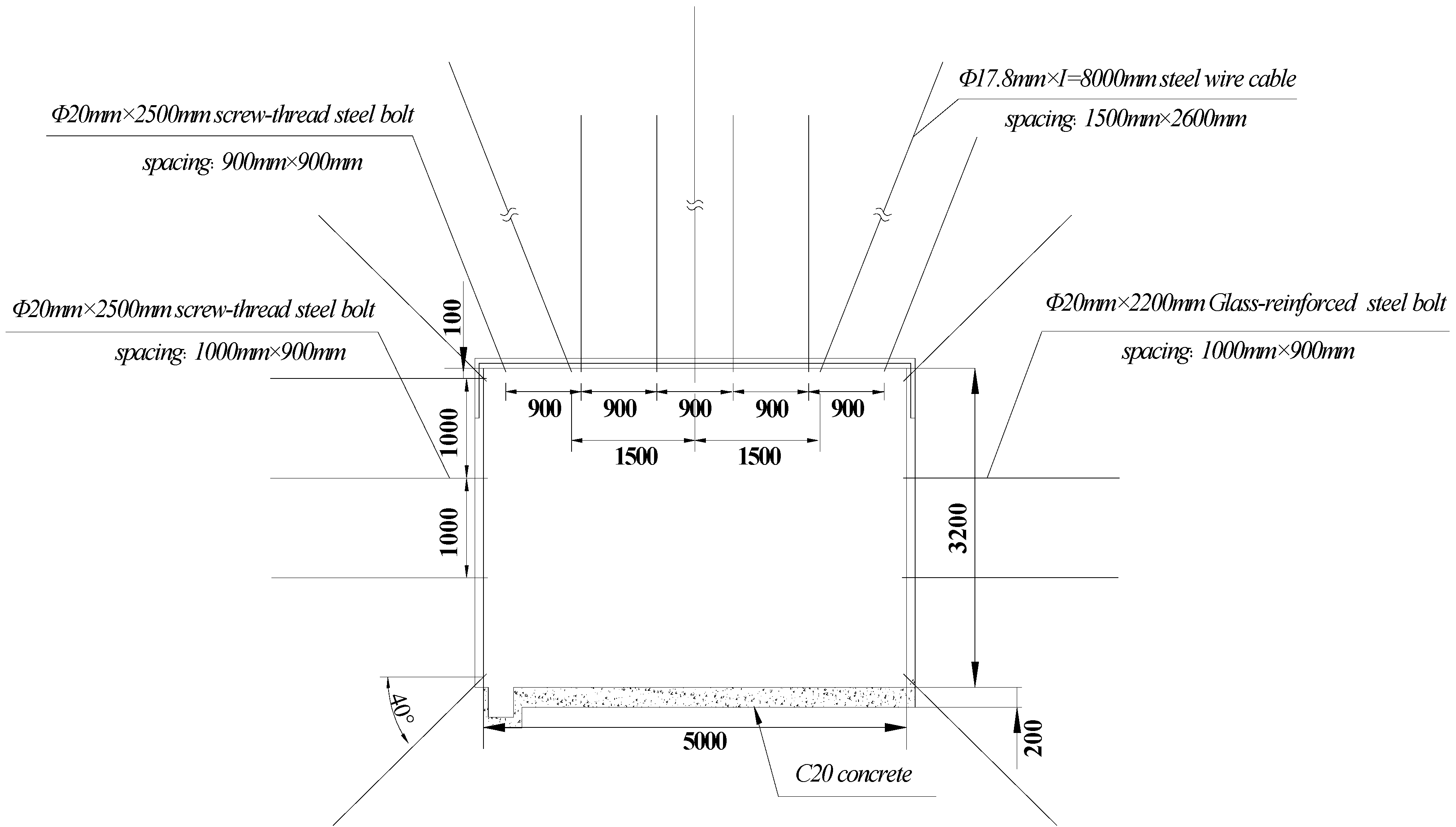
2.1. Engineering Geological Condition

Dananhu No.1 coal mine is located in the Hami region, Xinjiang. The #3 coal seam of main mining belongs to the typical soft roof–coal–floor coal seams. The average thickness of the coal seam is 6.5 m, the average inclination angle is 8°, and the buried depth of the coal seam is about 280 m. The shearer in the working face has a cutting height of 2.8 m and a discharging height of 3.5 m. The mining and discharging ratio is 1:1.25. The roof and floor slate layer is IV surrounding rock, while the floor is mainly composed of carbonaceous mudstone, sandy mudstone, and siltstone. Within about 4.0 m of the floor, there is a weak argillaceous rock mass, which is sensitive to the influence of mining. The direct roof is the low-strength argillaceous rock mass, which belongs to the extremely unstable type. The test results of the rock mechanics experiment (Table 1) show that the strength of the coal seam, roof, and floor is low, and it is easy to produce large deformation under the influence of mining.
The width of the auxiliary transport roadway is 5.0 m and the height is 3.2 m. The original support scheme (Figure 1) includes a rebar bolt with a roof plate of 20 mm × 2500 mm and anchor cable support of 17.8 mm × 8000 mm; the row spacing between bolts is 900 mm × 900 mm, and the row spacing between anchor cables is 1500 mm × 2600 mm. The south side adopts a 20 mm × 2200 mm fiberglass steel anchor rod, and the north side adopts a 20 mm × 2200 mm rebar steel anchor rod. The row spacing between the anchors is 1000 mm × 900 mm. The concrete with strength C20 is used to pave the bottom of the bottom plate without any strengthening support measures.

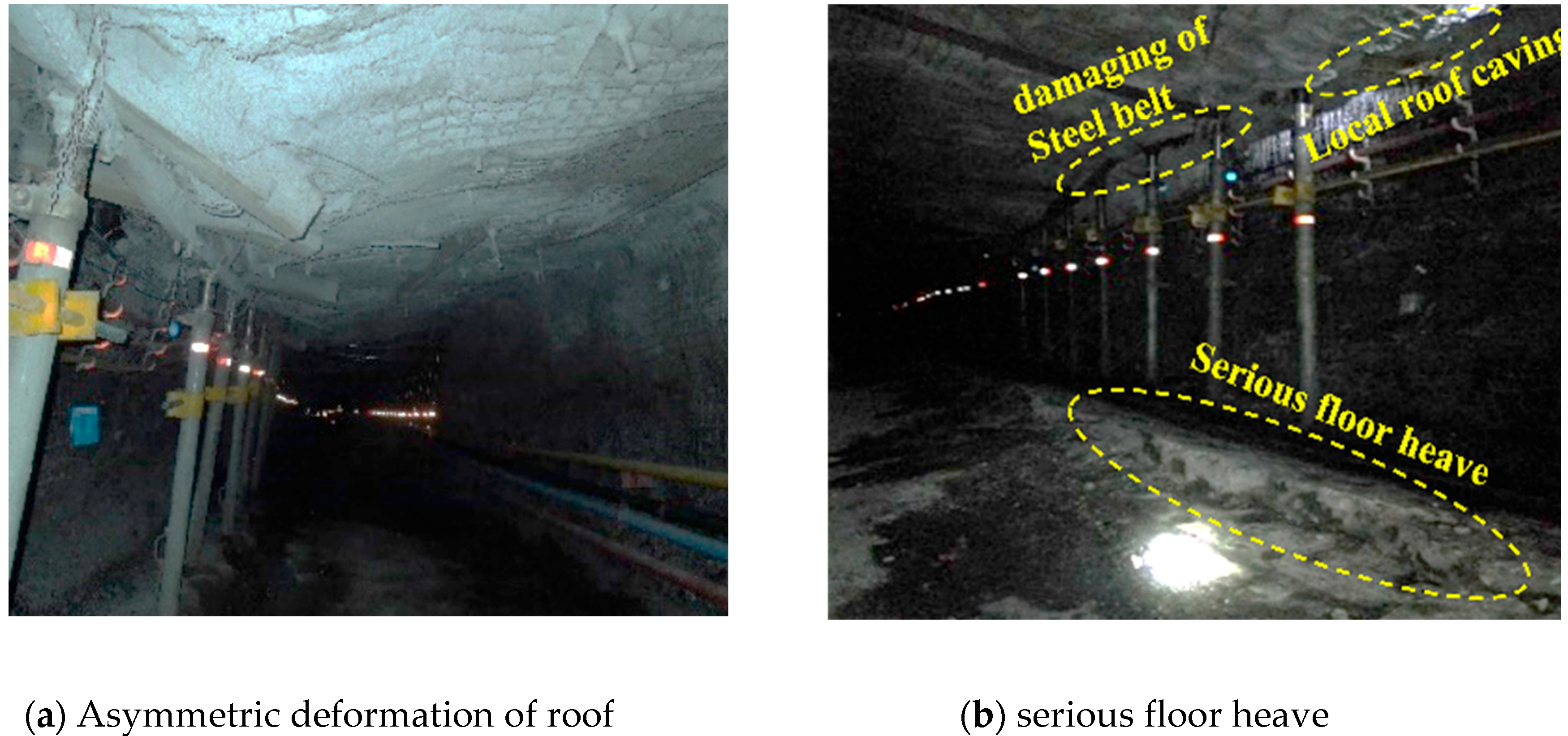
2.2. Roadway Deformation Characteristics

According to the field monitoring, under the original support condition, the two sides of the 1305 auxiliary transportation roadway are asymmetrically deformed due to the permeability of the V3 aquifer, groundwater, and the influence of mining. The south side is bulged seriously, the roof subsidence is large, and the two sides are moved closer than 400 mm. The convergence between the roof and floor is 1080 mm, part of the coal body of the top is relatively broken, and the soft rock of the bottom produces a large range of floor heave with a floor heave of 735 mm, as shown in Figure 2.

3. Mechanism Analysis of Roadway Floor Heave

3.1. Roadway Deformation Characteristics

According to the laboratory test and field investigation, the deformation and failure of the 1305 auxiliary transportation roadway is mainly manifested as serious bottom heave. Considering the surrounding rock conditions and original support design, the main influencing factors of roadway floor heave are as follows:
(1) Roadway surrounding rocks are extremely unstable
The #3 coal seam of Dananhu No. 1 coal mine is a soft roof-coal-floor coal seam, and the direct bottom of the 1305 working face is mudstone and siltstone, which is cemented by mud and expanded by water. We have tested the physical and mechanical parameters of the working face floor in the laboratory and obtained that the density of the rock is about 2.06 × 10³ kg/m3, the unidirectional compressive strength is 8.66 MPa, and the softening coefficient is 0.1. The roof and floor strata are of IV surrounding rock, which is extremely unstable.
(2) Significant influence of mining
After the operation of the working face, under the influence of high concentrated stress, the surrounding rock of the goaf produces serious plastic deformation. In addition, the surrounding rock is composed of mudstone and shale, which is easy to expand or decompose in the presence of water or under the influence of weathering. Soft rock has strong rheological characteristics, so the overall deformation is asymmetric, with large deformation near the goaf and small deformation near the coal pillar, which has been verified by field measurements.
(3) Damage of drainage ditch causes water seepage, deterioration, and expansion of the bottom plate
Groundwater can change the stress state and also affect the strength of the surrounding rock. The increase of pore water pressure on the structure plane reduces the normal stress on the structure plane, thus reducing the shear strength of rock mass. The lithology of 3# coal roof and floor of Dananhu No. 1 coal seam is soft, and the rock mass has low compressive strength. Therefore, in the process of loading and unloading, the ability of surrounding rock to resist deformation is greatly weakened by the influence of the V3 aquifer and groundwater seepage. Under the influence of mining, the rock structure surface of the roadway drainage ditch expands and causes damage. The wastewater, aquifer water, and working face water produced in the construction of the support structure infiltrate along the cracks of the damaged drainage ditch, resulting in the sharp reduction of the surrounding rock strength. This greatly intensifies the expansion of the floor mudstone and causes the continuous floor heave.
(4) Floor support is too little
According to the original support scheme, only a 0.2 m thick concrete layer is used for paving the roadway bottom, which is too little compared with the roadway roof. As the concrete pouring construction is carried out under the condition of no support of the floor, the soft rock floor is squeezed by two sides during the solidification of the concrete pouring, the overall solidification firmness is not strong, and a large number of defects occur in the initial stage, which cannot produce high strength inhibition to the floor heave.
The poor quality of rock mass belongs to the geological influence factors; the roadway can be relocated, but it is very difficult to deal with it after encountering. The mining influence and the weak support of the floor belong to the design influence factors, which are caused by a lack of understanding of geological conditions or the limited support technology, which can be effectively avoided; the damage of waterproof and drainage measures belongs to the construction and operation influence factors, which can be completely avoided. Therefore, after revealing the mechanism of floor heave, we should study the floor support and drainage measures in depth.

3.2. Roadway Deformation Characteristics

Based on the geological conditions and mining conditions of the 1305 auxiliary transportation roadway, a three-dimensional program was used to construct a numerical model to simulate the failure and instability of the 1305 auxiliary run through under the original support. The numerical calculation model (Figure 3) is 50 m long, 38 m high, and 9 m thick. The 1305 auxiliary run-along trench is rectangular: 5 m wide and 3.2 m high.
At the top of the model, a 7 MPa evenly distributed load was applied to simulate the gravity effect of coal and rock mass above the roadway, which was constrained at the bottom and around, with a total number of 69,610 elements and 78,386 nodes. The physical and mechanical parameters of the coal strata are shown in Table 1. The instability and deformation of the surrounding rock of the 1305 auxiliary haulage tunnel are investigated by calculation, and the mechanism of the roadway floor heave is revealed.
In the case of the original support (Figure 4), due to the soft surrounding rock and large Poisson’s ratio coefficient, which is influenced by the concentrated stress generated by coal pillars in that section, the roof displacement and subsidence amount are large, the deformation amount of the coal pillar side roof and floor is large, and the floor produces asymmetric deformation. The floor heave deformation is the overall bulge, and the middle part is the most severe. The roof subsidence is 350 mm, the maximum floor heave is 735 mm, and the displacement of the two sides of the roadway is 550 mm. Therefore, obvious grooves are formed between the floor heave and the side. The deformation value of the two shoulders is 200 mm, and the maximum displacement of the roof and floor is 1021 mm, accounting for 32% of the original roadway. The roadway presents the phenomenon of anti-arch floor heave, which is “large in the middle and small on both sides”. The distribution of horizontal displacement is such that the deformation of the upper part of the roadway is smaller than that of the lower part of the roadway, the maximum deformation of the middle and lower part is 450 mm, and the displacement of both sides of the floor is 500 mm, which is 10% of the roadway width.
Since the water inflow of the two sides of the roadway is different and the softening coefficient of the surrounding rock is low, the strength of the surrounding rock of the south side and the north side of the roadway are also different, resulting in the vertical stress of the south side of the roadway being transferred to the depth of the rock mass.
The vertical stress of roadway reaches its maximum at 2–3 m of the two sides (Figure 5). The distribution region of tensile stress on the north side is slightly larger than that on the south side, and the maximum tensile stress on the bottom plate is 0.7 MPa. The maximum horizontal stress is 21 MPa at 3.5–5 m of the roof and 3–4 m of the floor. The horizontal stress on the roof is greater than that on the floor, and the area of horizontal stress concentration is closer to the roof. The stress release phenomenon occurs in some areas of the floor due to the influence of mining, which leads to severe compression and flexure damage in this area. In the deeper region, the stress concentration is strong because the release limit is not reached. The force of the anchor rod and cable is relatively small in the roof area, and the force of the two shoulder angles increases to 150 kN. The force of the two anchors increases compared to the roof. The force of the two anchors reaches 309 kN within the range of 2 m.
Combined with field measurement, theoretical analysis, and numerical simulation, it is concluded that the deformation characteristics of the 1305 auxiliary transportation roadway are as follows: There is an obvious deflection in the middle area of the floor; both the legs and roof contract to the tunnel interior; and the floor undergoes anti-arch failure to the unrestrained side. Under the complicated conditions such as the influence of mining and unreasonable support, the high-strength extrusion of the two sides causes a large range of shear failure of the bottom slab. Finally, through comprehensive analysis, we think that the floor heave mechanism of 1305 auxiliary transportation is the extruding and flowing of floor heave.
Therefore, based on the above comprehensive analysis of the influencing factors of floor heave, we think that we should effectively deal with the floor, strengthen the support, and optimize the overall support parameters so that the “roof two sides floor” support can form a unified and effective whole.

4. Optimal Scheme of Roadway

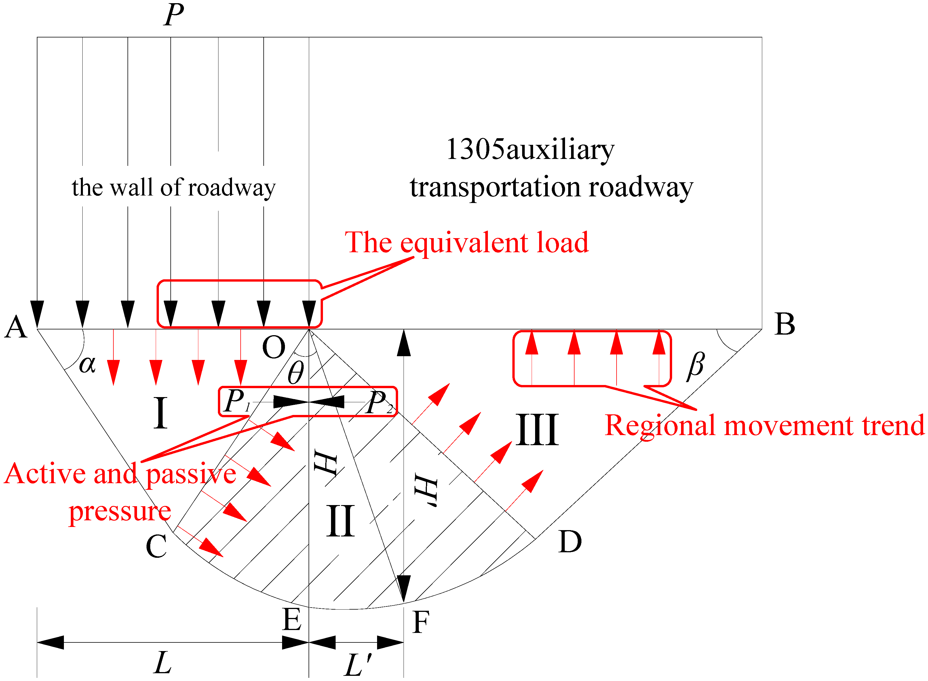
4.1. Theoretical Calculation of Support Parameter Optimization

In this paper, based on the theory of the ultimate bearing capacity of foundation, a mechanical model (Figure 6) is established to analyze the failure depth and regional movement trend of a roadway soft floor formed under the influence of mining, in order to lay a theoretical foundation for the optimization of support design. For the phenomenon of bottom heave of the 1305 auxiliary transportation roadway along the trough with extrusion flow, the width of the limit balance zone of the bottom plate should be calculated first, and then the maximum failure depth of the bottom plate should be obtained, so as to provide theoretical basis for the optimal support design of the bottom.
With the continuous advance of the working face, the side of the roadway will produce the effect of load transfer to the floor. Therefore, the floor rock in area I (active extrusion area) in Figure 6 presents an active extrusion state, which acts on the floor rock in area II (passive equilibrium area) to produce a passive sliding phenomenon, and then reaches the transition state of limit balance. Area III is the floor failure area, which is divided into floor stress release area and stress concentration area. The high stress concentration phenomenon occurs in the rock mass of area III under the passive compression of the rock mass in area II. When the stress concentration area reaches the release limit under the influence of mining, the stress release will occur. Therefore, the rock mass in the stress release area will deflect to the free side of the floor without reinforced support under the influence of the released high stress, resulting in floor heave [21,22,23,24]. When the limit equilibrium state is reached, the active pressure P1 and passive pressure P2 under floor rock mass can be expressed as [25,26,27,28]
P 1 = γ ( n + h + h ) K 1 2 C K 1
P 2 = γ n K 2 + 2 C K 2
where γ is the average of overburden bulk density, 25 kN/m3; n is the buried depth, 280 m; and h′ is the roadway height, 3.2 m. C is the cohesion of rock mass, taking 2 MPa.
K 1 = tan 2 ( π 4 φ 2 )
K 2 = tan 2 ( π 4 + φ 2 )
The height of the pressure arch (h) is
h = M 2 f ξ μ I n ( k γ n + C tan φ ξ C tan φ + ξ p ) + a 2 f
where k is the stress concentration coefficient, 1.8; μ is the friction coefficient, 0.52; f is the Platt’s coefficient, 0.8; ξ = (1 + sin φ)/(1 − sin φ); P′ is the roadway support strength, 1.2 mpa; M is the thickness of the coal, 6.5 m; a is the width of the roadway, 5 m; and φ is the internal friction angle, 27.4°.
The lane-side failure depth is
L = 2 cos ( π 4 + φ 2 ) h d max cos ϕ e ( π 4 + φ 2 ) tan φ = 2.26   m .
The failure depth of the roadway bottom plate is
H = L e ( π 4 φ 2 ) tan φ 2 cos ( π 4 + φ 2 ) = 3.05   m .
The maximum failure depth H of the roadway floor can be obtained by combining the above formulas
H = K 1 ( h + h ) K 2 K 1 2 C γ ( K 2 K 1 ) = 3.2   m .
The bolt adopts a square layout; then, the row spacing between bolts is
a = ( N β N 1 ) 1 2
where N is the anchor bearing capacity, KN; and N1 is bolt support reaction, MPa.
A = 0.82 m, so let’s take 0.8 m.
Field practice shows that 70% of the maximum failure depth of the roadway bottom plate is used as the anchor rod length of the bottom plate, which is 2.5 m.

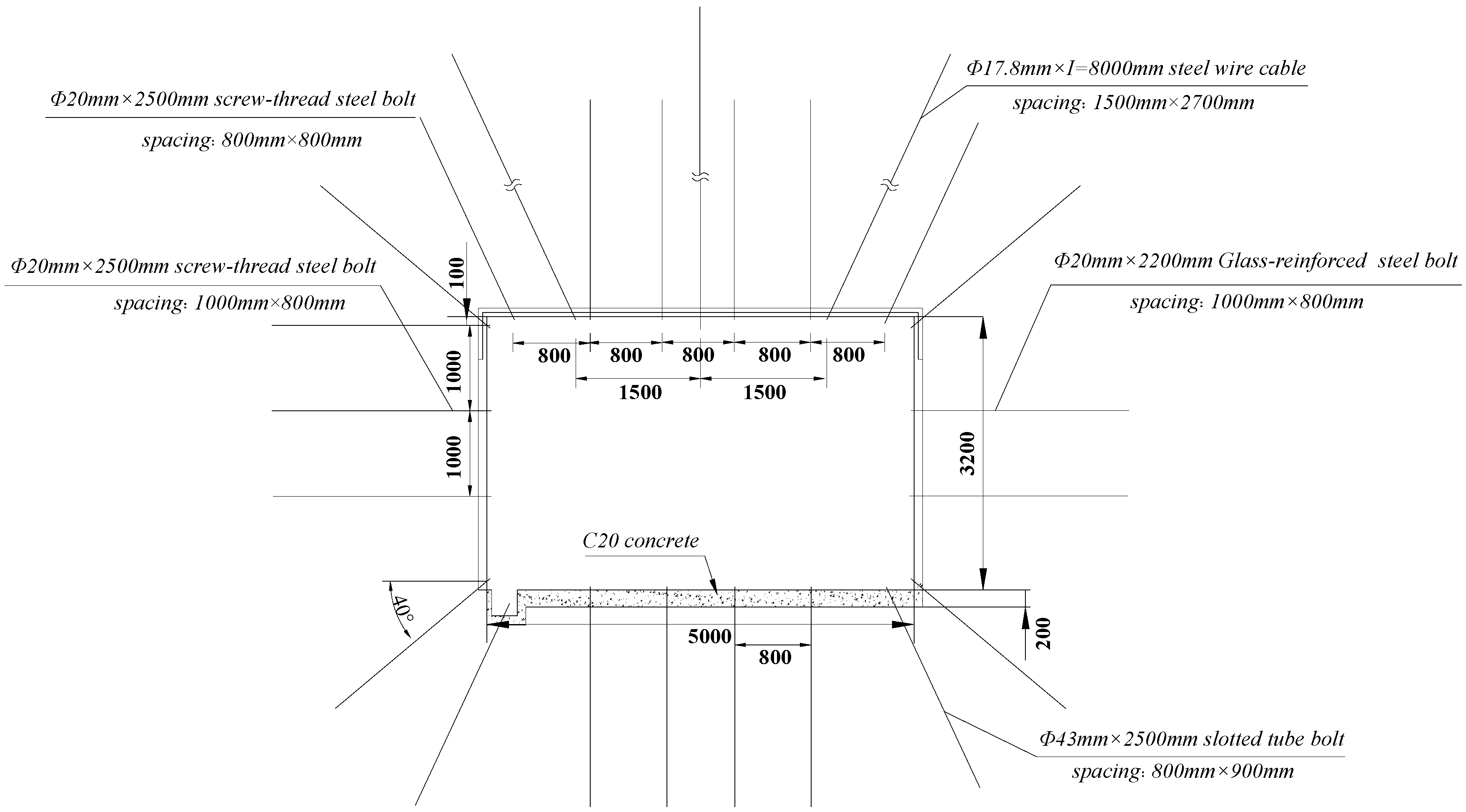
4.2. Determination of Optimal Support Scheme

Only concrete with strength C20 is used for paving the roadway floor along the transportation channel without any strengthening support measures. This is because the overall strength of the roadway surrounding rock is low and it is easy to produce the extruding and flowing of floor heave under the influence of water and mining. According to the field measurement and numerical simulation analysis, the plastic zone of the 1305 auxiliary transportation roadway is asymmetric, while the surrounding rock is affected by water, mining stress, and the unreasonable support structure, which leads to flow instability and the roadway being severely squeezed. Therefore, considering the economic and safe mining, we should strengthen the support of the roadway floor and the bottom side of the two sides, and improve the row spacing between the roof and side bolts.
According to the results of theoretical analysis and numerical simulation, based on the original support, the support reinforcement scheme of the floor pipe joint bolt support and the improvement of bolt spacing is proposed, as shown in Figure 7.
The roof is supported by six 20 mm × 2500 mm rebar bolts and three 17.8 mm × 8000 mm anchor cables. The angle between the bolts and the horizontal is 60°, the spacing between the bolts is 800 mm × 800 mm, and the spacing between the cables is 1500 mm × 2700 mm. The bottom plate adopts six pipe joints of 43 mm × 2500 mm. The included angle between the bolt and the horizontal is 60°, the row spacing between the bolt is 800 mm × 800 mm, and cement slurry is poured. (3) The south side adopts a 20 mm × 2200 mm fiberglass steel anchor rod, and the north side adopts a 20 mm × 2200 mm rebar steel anchor rod. The row spacing between the bolts is 1000 mm × 800 mm.

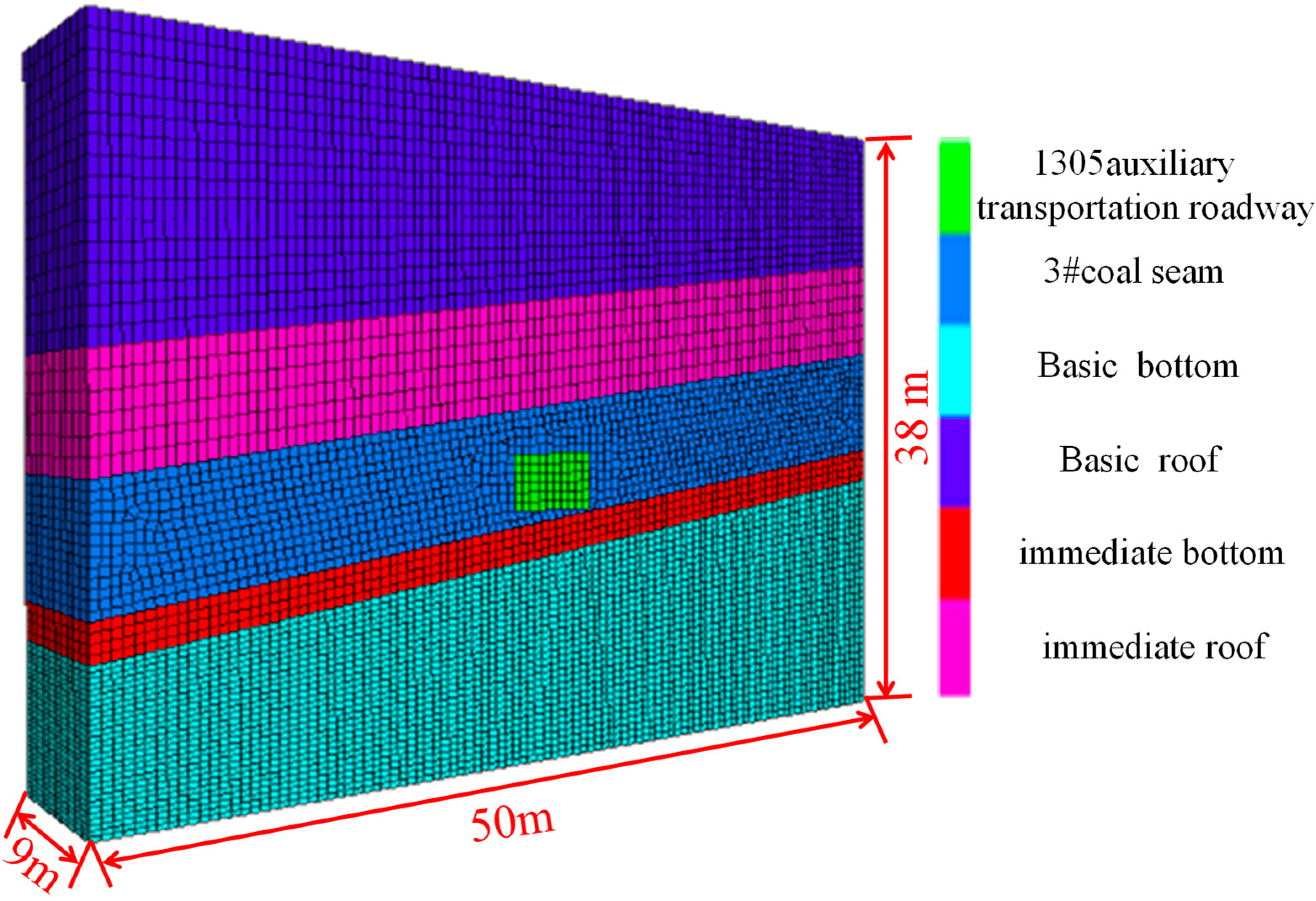
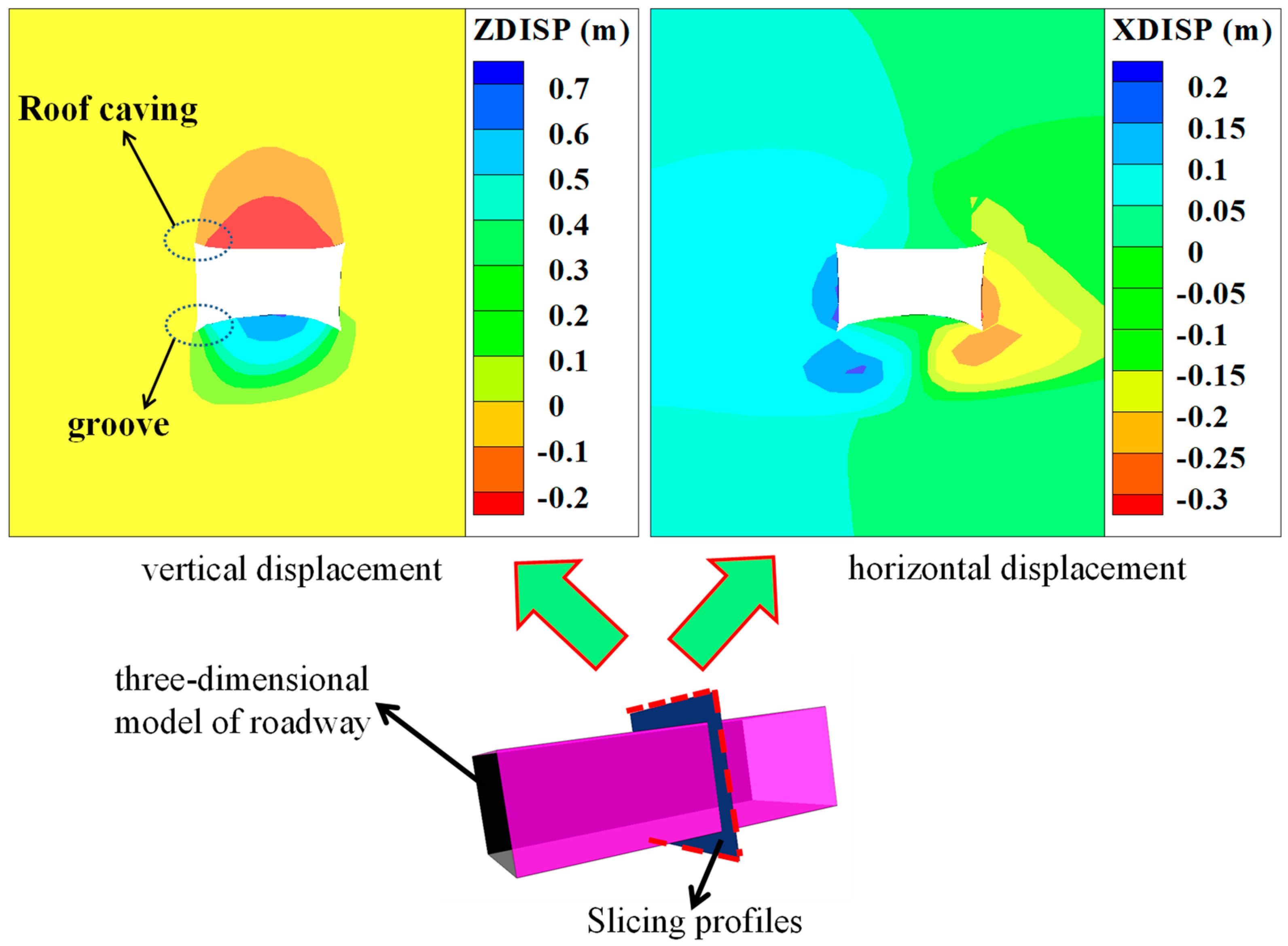
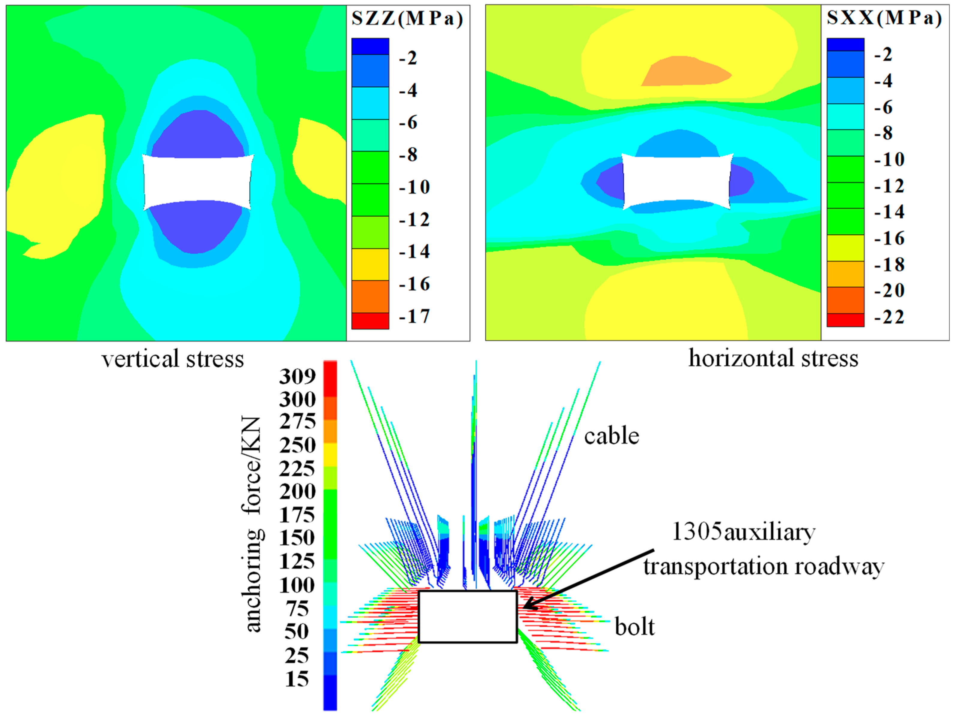
5. Numerical Simulation of Deformation and Failure of Roadway Optimization Support

In order to preliminarily verify the feasibility of the 1305 auxiliary transportation roadway strengthening support scheme, the 1305 auxiliary transportation roadway along the trough bottom heave numerical calculation model was used to conduct strict and real numerical simulation according to the optimized support scheme. Cable and shell structural units were used for simulation, respectively. The numerical model was used for preliminary simulation verification of the optimized scheme, and the results are shown in Figure 8.
According to the analysis, the surrounding rock deformation trend after the support optimization is relatively uniform, and the displacement of the two sides is reduced from 550 mm to 370 mm. The floor heave decreased from 735 mm to 268 mm; the reliable bearing structure formed by the pipe joint bolt can effectively restrain the dilatancy and extrusion flow in the anchorage area of floor rock and ensure the stability of the surrounding rock. The stress environment in the floor area of the roadway support has been significantly improved, with the stress of the two anchor bars at the bottom of the roadway support being about 90 kN and that of the anchor bars at the bottom of the roadway support being up to 100 kN. This has significantly improved the stress state of the area, and the phenomenon of internal displacement has basically disappeared, effectively exerting the overall bearing capacity of the rock strata and support body in the floor anchorage area. This is because the support strength of the roadway floor is increased, and the extrusion flow of the floor to the free side is further weakened by controlling the source of the instability of the floor rock. Then, the erosion of the floor water on the support body is weakened by bolt grouting, and the normal stress in the sliding area of the floor is increased. Finally, the side angle bolt of the floor is used to cut off the stress transmission path of the two sides of the extrusion effect, and through the anchor rod, the active force is exerted on the floor rock to prevent the soft and broken floor mudstone from flowing into the free space of the roadway side.

6. The Engineering Application

After the optimized support scheme was applied to the field practice of the Dananhu No. 1 Mine, the roadway displacement was monitored by the cross-point method, and the distance–deformation curve was obtained, as shown in Figure 9. As can be seen in Figure 9, the floor heave after roadway support decreased from 735 mm to 268 mm, which decreased by 64% compared with the original support scheme. The displacement of the two sides decreased from 550 mm to 370 mm, and the roof and floor deformation also decreased significantly and gradually stabilized. The optimized support scheme had a good effect on floor heave control, and the surrounding rock stability of the roadway was high.

7. Discuss

At present, the methods of coal mine floor support include no support or only consider a single floor support, not considering whether the overall support structure of the surrounding rock is reasonable. Due to the special geological conditions of the three soft coal seams, many factors should be considered when optimizing the support structure. Therefore, the research scheme needs to be further discussed regarding whether the bottom heave treatment of the three soft coal seams is correctly applied.
In order to support the floor reasonably and effectively, the most important thing is to determine the maximum failure depth of the floor. Most of the research on the maximum failure depth of the floor is calculated by numerical simulation. According to the mechanical parameters of each rock layer, this paper not only through numerical simulation calculation, but also obtains the maximum failure depth of the roadway floor by establishing the mechanical model (Equation (8)) is 3.2 m.
It can be seen from Table 2 that according to the numerical calculation model established this time, the maximum damage depth of the bottom plate is 3.4 m, and the maximum damage depth of the bottom plate can be 3.2 m by using the mechanical theory calculation. According to the field measurement data, the water diversion height of the block mining face is 3.0 m.
The results show that the calculation results of the maximum failure depth of the floor obtained by the numerical calculation model and the mechanical model are basically consistent with the field results. Therefore, after grouting the floor and strengthening the support and optimizing the two sides of the support, the overall stress field of the roadway has been improved obviously. The stress of the two side bolts is reduced from 309 kN to 90 kN, and the stress of the bottom bolt is 100 kN. The “squeezing effect” of the two side bolts on the bottom plate is effectively alleviated, and the amount of the bottom drum is reduced from 735 mm to 268 mm, which shows that the optimized support can achieve the effective treatment of the bottom drum, and verifies the high reliability of the calculation model.

8. Conclusions

(1) The 1305 auxiliary transportation roadway is a typical roadway of “soft roof–coal–floor coal seams”. Under the comprehensive influence of mining operation and water in the fully mechanized caving face, the area at the bottom of the two sides will shrink inwards, the rock strata in the floor will form an anti-arch bulge, and the roof will produce obvious subsidence. The soft rock in the floor has low strength, which is typical of extrusion flow floor heave.
(2) Through theoretical analysis and numerical simulation, it is concluded that the maximum failure depth of the roadway floor is 3.2 m, the failure depth of the roadway side is 2.26 m, and the failure depth of the roadway side floor is 3.05 m. It is calculated that the length of anchor rod used for strengthening support of the bottom plate is 2.5 m.
(3) Numerical calculation and field practice show that the optimized support scheme has a good control effect on roadway floor heave, and the displacement of the two sides is reduced from 550 mm to 370 mm; the floor heave decreased from 735 mm to 268 mm; the stress of the rock bolts of the two sides decreased from 309 kN to 90 kN, and the strength of the mudstone of the floor increased after grouting strengthening, which effectively alleviated the “extrusion” effect of the two sides on the soft rock of the floor. The overall surrounding rock system could achieve long-term stability after the optimized support of “top-bottom-side”.

Author Contributions

P.S. conceived, designed and analyzed the test results; H.X. performed the experiments and wrote the manuscript; X.L., Y.K., Z.W. and X.W. supervised the research work; All six authors revised and proofread the manuscript. All authors have read and agreed to the published version of the manuscript.

Funding

Financial support for this work was provided by the National Natural Science Foundation of China (No. 51904227), the 973 Key National Basic Research Program of China (No. 2015CB251602), the Natural Science Foundation of Shaanxi Province (No. 2018JQ5194), the China Postdoctoral Science Foundation (No. 2017M623328XB), the Science and Technology Innovation Team Project of Shaanxi Province (No. 2018TD-038), the Hunan Province Engineering Research Center of Radioactive Control Technology in Uranium Mining and Metallurgy, the Hunan Province Engineering Technology Research Center of Uranium Tailings Treatment Technology (No. 2018YKZX2001), and the Opening Project of Cooperative Innovation Center for Nuclear Fuel Cycle Technology and Equipment, University of South China (No. 2019KFY25). Support from these agencies is gratefully acknowledged.

Conflicts of Interest

The authors declare no conflict of interest.

References

  1. Yu, W.J.; Wu, G.S.; Liu, H. Deformation characteristics and stability control of soft coal—Rock mining roadway in thin coal seam. J. China Coal Soc. 2018, 43, 2668–2678. [Google Scholar]
  2. Kang, H.P.; Wang, J.H.; Lin, J. High pretensioned stress and intensive bolting system and its application in deep roadways. J. China Coal Soc. 2007, 32, 1233–1238. [Google Scholar]
  3. Li, W.T.; Li, S.C.; Xuan, C. Mechanism and control of failure of rock roadway support in highly stressed soft rock. Chin. J. Rock Mech. Eng. 2015, 34, 1836–1848. [Google Scholar]
  4. Kang, H.P.; Lu, S.L. Research on mechanism of floor heave of roadway. Chin. J. Rock Mech. Eng. 1991, 10, 362–373. [Google Scholar]
  5. Jiang, Y.D.; Zhao, Y.X.; Liu, W.G. Research on floor heave of roadway in deep mining. Chin. J. Rock Mech. Eng. 2004, 23, 2396–2401. [Google Scholar]
  6. Bai, J.B.; Li, W.F.; Wang, X.Y. Mechanism of floor heave and control technology of roadway induced by mining. J. Min. Saf. Eng. 2011, 28, 1–5. [Google Scholar]
  7. Chen, Y.G.; Lu, S.L. China Coal Mine Roadway Surrounding Rock Control; China University of Mining and Technology Press: Xuzhou, China, 1994; pp. 463–469. [Google Scholar]
  8. Hua, X.Z.; Lu, X.Y.; Li, Y.F. Prevention and control technology of floor heave in gob-side entry retaining with large section of deep mine. Coal Sci. Technol. 2013, 41, 100–104. [Google Scholar]
  9. Sun, X.M.; Miao, P.Y.; Shen, F.X. Study on floor heave mechanism of horizontal layered soft rock roadway in deep well under different stress states. J. Min. Saf. Eng. 2018, 35, 1099–1106. [Google Scholar]
  10. Sungsoon, M.; Kudret, T.; Serkan, S. Management of floor heave at Bulga Underground Operations—A case study. Int. J. Min. Sci. Technol. 2019, 29, 73–78. [Google Scholar]
  11. Zhang, Z.; Shimada, H. Numerical Study on the Effectiveness of Grouting Reinforcement on the Large Heaving Floor of the Deep Retained Goaf-Side Gate road: A Case Study in China. Energies 2018, 11, 1001. [Google Scholar] [CrossRef] [Green Version]
  12. Gong, P.; Ma, Z.; Ni, X.; Zhang, R.R. Floor Heave Mechanism of Gob-Side Entry Retaining with Fully-Mechanized Backfilling Mining. Energies 2017, 10, 2085. [Google Scholar] [CrossRef] [Green Version]
  13. Wang, J.; Hu, C.c.; Zuo, J.P. Mechanism of roadway floor heave and control technology in fault fracture zone. J. China Coal Soc. 2019, 44, 397–408. [Google Scholar]
  14. Wang, G.Y.; Jin, L. Study on dynamic responses of roadway controlled by borehole pressure relief and prestressed grouting anchor cable on the floor under dynamic load. Chin. J. Appl. Mech. 2017, 34, 881–886. [Google Scholar]
  15. Wang, X.Q.; Kan, J.G.; Jiao, J.K. Mechanism of floor heave in the roadway with high stress and soft rock and its control practice. J. Min. Saf. Eng. 2017, 34, 214–220. [Google Scholar]
  16. Huang, Q.X.; Hao, G.G. Research on the floor failure range and its effects of entry. J. Xi’an Univ. Sci. Technol. 2018, 38, 51–58. [Google Scholar]
  17. Hua, X.Z.; Yang, P. Floor deformation dynamic evolution of gob-side entry retaining with large section in deep mine. J. China Univ. Sci. Technol. 2018, 47, 494–501. [Google Scholar]
  18. Hua, X.Z.; Yang, P.; Liu, Q.J. Model test on evolution mechanism of floor heave in gob-side retaining entry of deep mine. J. Min. Saf. Eng. 2018, 35, 1–9. [Google Scholar]
  19. Hua, X.Z.; Li, Y.F. Mechanics analysis on floor deformation of gob-side entry retaining and prevention and control of floor heave. J. China Coal Soc. 2016, 41, 1624–1631. [Google Scholar]
  20. Lai, X.P.; Xu, H.C.; Kang, Y.L. Analysis on “spatio-tempo-intension” evolution rules of overburden strata movement in fully mechanized top-coal caving face. J. Xi’an Univ. Sci. Technol. 2018, 38, 871–877. [Google Scholar]
  21. Zuo, J.P.; Sun, Y.J.; Li, K. Study of the reinforced supporting length and floor heave control technology of soft rock roadway influenced by collapse column. J. China Univ. Min. Technol. 2017, 46, 18–26. [Google Scholar]
  22. Shan, P.F.; Lai, X.P. Mesoscopic structure PFC~2D model of soil rock mixture based on digital image. J. Vis. Commun. Image Represent. 2019, 58, 407–415. [Google Scholar] [CrossRef]
  23. Shan, P.F.; Lai, X.P.; Liu, X.M. An associated evaluation methodology of initial stress level of coal-rock masses in steeply inclined coal seams, Urumchi coal field, China. J. Eng. Comput. 2020. [Google Scholar] [CrossRef]
  24. Zhang, N.; Shi, X.L.; Zhang, Y. Tightness analysis of underground natural gas and oil storage caverns with limit pillar widths in bedded rock salt. J. IEEE ACCESS 2020. [CrossRef]
  25. Chen, Z.Y.; Zhou, J.X.; Wang, H.J. Soil Mechanics; Tsinghua University Press: Beijing, China, 1992. [Google Scholar]
  26. Qian, M.G.; Shi, P.W. Mine Pressure and Strata Control; China University of Mining and Technology Press: Xuzhou, China, 2003. [Google Scholar]
  27. Hou, C.J.; He, Y.N.; Li, X. Reinforcing sidewalls and corners of gateway to control floor heave. J. China Coal Soc. 1995, 20, 229–234. [Google Scholar]
  28. Huang, Q.X.; Zheng, C. Theory of self stable ring in roadway support. Rock Soil Mech. 2016, 37, 1231–1236. [Google Scholar]
Figure 1. Design of the original roadway support.
Energies 13 00381 g001
Figure 2. Measuring of surrounding rock deformation of the 1305 roadway.
Energies 13 00381 g002
Figure 3. FLAC3D numerical calculation model.
Energies 13 00381 g003
Figure 4. Contour of displacement of surrounding rock.
Energies 13 00381 g004
Figure 5. Contour of stress of surrounding rock and cable.
Energies 13 00381 g005
Figure 6. Model of limit destroy depth of the floor.
Energies 13 00381 g006
Figure 7. New support section design diagram.
Energies 13 00381 g007
Figure 8. The numerical simulation result of the new support design.
Energies 13 00381 g008
Figure 9. Comparative analysis of correlation characteristics after optimized support.
Energies 13 00381 g009
Table 1. Physical and mechanical parameters of rock.
Density (kg·m−3)Cohesion (MPa)Angle of Internal Friction (º)Bulk E (GPa)Shear E (GPa)Tension (MPa)
Basic Roof21005.35307.82.80.34
Immediate Roof22203.229.96.82.40.48
#3 Coal Seam13002.0227.44.40.50.45
Immediate Bottom20602.5728.66.81.90.42
Basic Bottom21203.0728.26.81.90.33
Table 2. Analysis and comparison of the maximum failure depth of the floor.
Maximum Failure Depth of the FloorBorehole Observation ResultsNumerical Simulation ResultsCalculation Results of Mechanical Model
3.0 m3.4 m3.2 m

