Article

A Novel Energy Recovery System Integrating Flywheel and Flow Regeneration for a Hydraulic Excavator Boom System

1
School of Mechatronic Engineering, China University of Mining and Technology, Xuzhou 221116, China
2
Research and Development Center for Intelligent Manufacturing Technology of Engineering Equipment, Xuzhou College of Industrial Technology, Xuzhou 221140, China
3
George W. Woodruff School of Mechanical Engineering, Georgia Institute of Technology, Atlanta, GA 30332, USA
*
Author to whom correspondence should be addressed.
Energies 2020, 13(2), 315; https://doi.org/10.3390/en13020315
Submission received: 4 November 2019 / Revised: 30 December 2019 / Accepted: 8 January 2020 / Published: 9 January 2020
(This article belongs to the Special Issue Flywheel Energy Storage Systems and Applications)

Abstract

:
Implementing an energy recovery system (ERS) is an effective solution to improve energy efficiency for hydraulic excavators (HEs). A flywheel energy recovery system (FERS) is proposed based on this concept. A hydraulic pump motor (PM) is employed as the energy conversion component and a flywheel is used as the energy storage component. Since the pressure is low because the bucket is usually empty as the boom lowers, a relatively large PM should be used in the FERS. To overcome this drawback, a novel compound energy recovery system integrating flywheel and flow regeneration (FFERS) is proposed in this paper. The working principle of the system is analyzed in detail. The introduction of flow regeneration has two benefits; one is downsizing the displacement of PM and the other one is an extra improvement of energy efficiency. The primary parameters of both are matched based on a 4 t excavator. Compared with the PM used in the FERS, the PM displacement in the FFERS is reduced by 71%. For comparison, a general model that can operate in either the FERS mode or the FFERS mode is developed in AMESim. The modeling results show that the FFERS with a downsized PM contributes a 13% increase in energy recovery and reutilization efficiency (62%) as compared with the FERS.

1. Introduction

Hydraulic excavators (HEs) are commonly used throughout the world in infrastructure construction, forestry stations, and other industries. As the most widely used construction machineries, HEs consume lots of fuel and are characterized by low fuel efficiency and high emissions [1]. Since more concerns are arising regarding fossil fuel conservation and climate change, HE manufacturers and researchers are contributing to the study of these topics. During the operation of HEs, a great deal of energy converts into heat during the descent of the boom, and the braking of the rotating platform. It is of great significance determine if the wasted energy in a conventional HE can be recovered and reused in a follow-up motion to improve the energy efficiency. Similar energy wastage problems are also found in other actuators of the HE, but the boom shares the largest part, more than half of the total recoverable energy [2]. Therefore, this paper focuses on the potential energy wastage problem of the boom. Over the past decade or two, various energy recovery systems (ERSs) have been researched to alleviate this problem. In general, according to the different energy forms in an ERS, existing ERSs can be divided into the following three catalogs: electrical ERS [3], hydraulic ERS [4], and mechanical ERS [5].

2. State of the Art

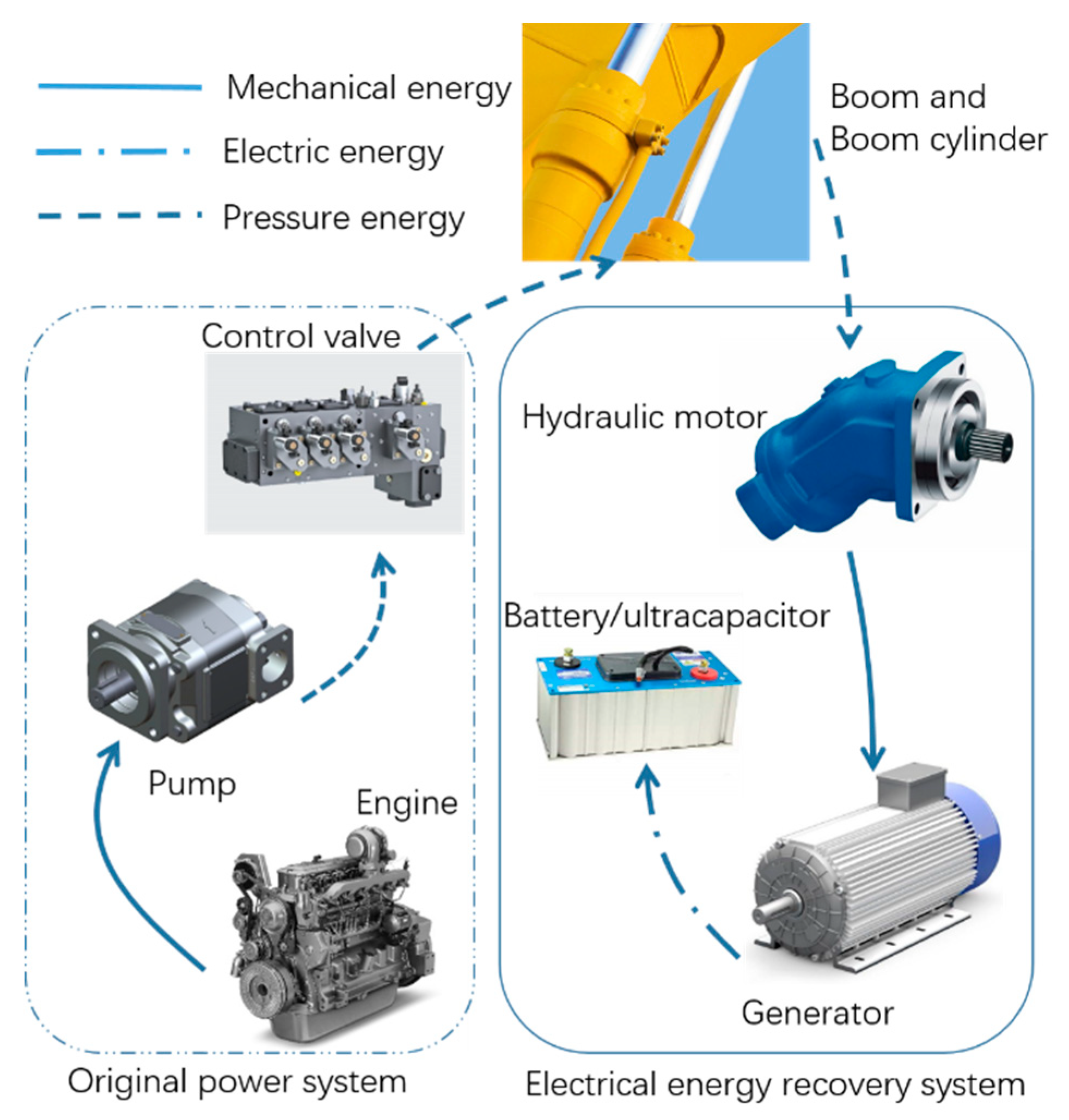
2.1. Electrical ERSs

An electrical ERS is the first type to be studied for HEs. An electrical ERS uses a hydraulic motor-generator as an energy conversion component. In a hybrid HE with an electrical ERS, the recaptured energy is either stored in batteries or ultracapacitors. A battery stores energy chemically, whereas an ultracapacitor stores it electrically [6]. Figure 1 illustrates the schematic of hydraulic excavator boom system equipped with an electrical energy recovery system.
There are many types of off-shelf batteries to choose from when designing a hybrid system, for example, a lithium-ion battery. Batteries tend to show high specific energies, while ultracapacitors have comparatively higher specific powers, but relatively lower specific energies [7]. Kanezawa et al. [8] first put forward a scheme of using an electric hybrid system to improve energy efficiency for excavators. Wang made significant contributions to electrical ERSs and developed a prototype for a 20 t hybrid HE [9]. Wang et al. [10] proposed a pressure-compensated ERS with a hydraulic motor and electrical generator installed in the return line. Experiments demonstrate that the energy recovery efficiencies are around 60% in different conditions. Considering the short operating period and the amount of potential energy, both the hydraulic motor and motor-generator of the electrical ERS usually should be large. Obviously, this leads to higher manufacturing costs and more installation space. To solve this problem, Lin et al. developed a compound energy recovery scheme using a bladder accumulator as a temporary energy storage device to extend the energy conversion time, and thereby reducing the installed power of the generator by 60% [11]. Meanwhile, the compound system gains a higher energy recovery rate of the boom potential energy, i.e., up to 41% as compared with 17% of the baseline [12]. As the latest progress, Chen et al. placed a throttling valve in the inlet of the hydraulic accumulator to improve the dynamic performance. The simulations indicate that the efficiency is about 58% [13]. Yu et al. proposed a novel energy regeneration boom system in which a hydraulic motor is installed between the boom cylinder and the main control valve. Rotational speed and generator torque are both regulated by controlling the displacement of the hydraulic motor [14]. The resulting energy regeneration efficiency varies from 33.8% to 57.4%. Minav et al. studied an electro-hydraulic forklift which is controlled by an electric servo motor and hydraulic pump motor (PM) [15,16]. Different setups for using the battery and ultracapacitor combinations as energy storage devices were investigated and the energy-saving ratio was up to 54%. Table 1 summarizes these architectures. It should be noted that a complex power train was produced by the various components, i.e., the batteries/ultracapacitors, relevant power electronics, and the motor-generator, resulting in difficult the maintenance, and an increase in the cost, weight, and package. A substantive obstacle for an electrical ERS with batteries is the short deep cycle life, approximately 1500 to 4500 cycles [17], which is far from the HEs’ requirements. Additionally, converting potential energy to mechanical energy, then, electrical energy and, at last, chemical energy and vice versa produce rather poor system efficiencies, which substantially prolong the payback period.

2.2. Hydraulic ERSs

Hydraulic ERSs utilize hydraulic accumulators as energy storage components, which store recovered energy in the form of pressure energy, as displayed in Figure 2. Compared to electric ERSs, hydraulic ERSs are more favorable in the conventional HEs because of the convenience of integration with existing power systems. L. Bruun of Caterpillar developed a 50 t HE prototype with a hydraulic ERS [18]. Compared with a conventional HE, the prototype gains an up to 37% fuel-savings efficiency during the boom ascent. Aiming to obtain a more compact hydraulic ERS, L. Quan et al. proposed a direct recovery scheme for the excavator boom based on a hydraulic accumulator [19,20]. Specific designs are achieved by either adding a counterbalance cylinder or using a novel three-chamber hydraulic cylinder instead of a conventional one. Real tests indicate that the energy recovery efficiency can reach up to 49.1% and 70.9%, for a 76 t and 6 t excavators, respectively. Zhou et al. put forward a closed hydraulic system for excavators using a three-chamber hydraulic cylinder and an accumulator. Simulation results demonstrate that the proposed scheme can reduce the power and energy requirements of the system by more than 50% [21]. A similar architecture for a hydraulic crane with an electro-hydraulic load sensing system was studied by Liang et al. [22]. Minav et al. [16] investigated using a hydraulic ERS on a hydraulically operated forklift and reported an energy-saving efficiency of 45%. Zhang et al. [23] investigated a direct drive system based on a decentralized hydraulics concept. Two fixed displacement pump/motors with a coaxial installed speed-controlled electric servo motor directly controlled the amount of fluid pumped into and out from the corresponding boom cylinder. Additionally, a hydraulic accumulator was employed as a tank and another one to balance the flow rate inequality of the two chambers of boom cylinder. According to the simulation, the energy efficiency of the boom system was 67.5%. Hydraulic accumulators have many merits, such as high-power density, fast charging and discharging, reliability, and cost-effectiveness. Despite this, the main drawback is the lower energy density [3], which constitutes a significant barrier in further development and application of hydraulic ERS. Another barrier is that the pressure in the accumulator after energy recovery is generally lower than that needed for driving the boom because the bucket is usually empty when the boom lowers, whereas fully loaded when the boom goes up. This inconveniences the reuse of recovered energy. Zhao et al. [24] researched a scheme using a hydraulic ERS to achieve the reutilization of recovered energy by releasing the energy to the inlet of the hydraulic pump. Simulations indicate that it can realize an energy-saving rate of up to 14.8%. Pettersson et al. [25] and Shen et al. [26] studied two schemes of using a hydraulic transformer to match the pressure between the hydraulic cylinder and accumulator, respectively. The latter reported that the fuel consumption could be reduced from 51.6 g to 30.1 g for each working cycle [26]. Jing et al. [27] reported on a novel asymmetric pump with three ports used to fulfill the potential energy recovery, which could improve energy efficiency by 17.5%. The outline of these schemes based on hydraulic ERS are also given in Table 1. The main shortcoming of these methods is that both the hydraulic transformer and the three ports pump are relatively sophisticated, and there are no commercial products for selection.

2.3. Flywheel-Based ERSs

A flywheel-based ERS is one common mechanical ERS for storing large amount of energy (in the order of tens to hundreds of kJ) from large size machinery. The flywheel is an old means of energy storage. Several decades ago, bulky structures caused by low strength materials and excessive energy losses caused by traditional bearings were the main barriers that made flywheels difficult to implement in mobile equipment. Recent advances in materials and advanced bearing technology have made this technology attractive again [28]. Energy can be transferred into the flywheel electrically, hydraulically, or mechanically [29]. Either an electric motor or hydraulic motor can be employed as its energy conversion component when adopting an electrical or a hydraulic system. However, no energy conversion component is possible in a purely mechanical system since no energy conversion happens. Sometimes, an auxiliary transmission is needed to transfer energy to or from the flywheel. The amount of energy of a flywheel depends on the moment of inertia and how fast it rotates. There are several advantages that make the flywheel attractive as an energy storage component which include: high power density, long cycle life, fast response time, no degradation over time, and easily estimated state-of-charge [30,31]. Flywheel ERSs (FERSs) are becoming increasingly prevalent in automotive and commercial vehicle applications since the famous introduction in racing cars during the 2009 Formula1 motorsport season [32]. A carbon filament wrapped flywheel with a mass of 5 kg was used in the F1 racing car to recover the braking energy that could spin up to 64,000 rpm. The flywheel could deliver up to 60 kW of power to accelerate the vehicle. At present, FERSs has many successful examples in various industrial and mobile applications, such as power quality improvement, renewable energies integration support [33], braking energy recovery of hybrid electric vehicles [34], and heavy haul locomotives [35]. Figure 3 illustrates the automobile application schematic, in which a flywheel-based ERS is adopted to recover the braking energy. In 2011, Volvo developed a passenger car prototype that uses a flywheel system produced by PUNCH Flybrid company for recovering braking energy and reutilizing the captured energy in a future acceleration. The flywheel can provide an extra 80 horsepower as the vehicle accelerates while reducing fuel consumption by 25% [36]. The application of flywheel energy storage in construction machinery is still in its infancy phase. Some scholars studied the feasibility of using a FERS in the field of construction machinery, such as forklift trucks [37]. However, there are few publications relating to the application of flywheel energy recovery in HEs. Ricardo [38] disclosed a 17 t wheel excavator using flywheel energy storage. The flywheel unit has a 200 kJ energy storage capacity with a peak power rating of 101 kW. It has been verified by tests that the excavator can save approximately half of the total potential energy theoretically available on a materials handling cycle. From the development of vehicle braking energy recovery technology, a FERS seems to be a possible solution to regenerate the otherwise wasted energy in HEs.

2.4. Flow Regeneration

Flow regeneration is a common energy-saving method in HEs. Figure 4 gives the schematic of the flow regeneration. This function can be achieved by integrating a regeneration valve in the main control valve. When the boom lowers, the regeneration valve divides part of the fluid from the cap side into the rod side of the boom cylinder, which reduces the flow requirement for the hydraulic pump. Choi et al. [39] simulated an independent metering system with flow regeneration function, which can decrease energy consumption by 44%. Notably, the main factor of energy-saving effect is not the flow regeneration function. Although the flow being saved is considerable, because the pressure of the rod side is generally low when the boom lowers, the energy-saving effect is limited [40].

3. Outline

This paper presents an investigation of the energy-saving opportunities enabled by the implementation of a novel compound energy recovery system integrating flywheel and flow regeneration (FFERS) for HE booms. It is easy to qualitatively describe the benefits from energy harvesting of HEs, but a much more difficult analysis should be done to quantify these benefits. The paper is organized as follows: In Section 4, the novel architecture is proposed and its working principle is presented in detail; in Section 5, the mathematical model is developed and the parameters of the FFERS are described; the simulation model built in AMESim software is given and the energy-saving potential achievable by the FFERS is evaluated in Section 6. Simulations are carried out to evaluate the performances of the FERS for comparison. In this section, the benefits of the introduction of flow regeneration are discussed; and concluding remarks are provided in Section 7.

4. Proposed Architecture

4.1. Our Previous Flywheel Energy Recovery System (FERS)

In previous research [41], a FERS was proposed for harvesting HEs’ boom potential energy. Figure 5 demonstrates the hydraulic circuit. The FERS can be divided into two parts. The left part is a conventional valve-controlled circuit of the HE boom, and the right is an energy recovery circuit. A conventional valve-controlled circuit mainly consists of a hydraulic pump, a boom cylinder, and a proportional directional control valve. A diesel engine drives the pump and the proportional directional control valve controls the motion of the boom cylinder. The energy recovery circuit is composed of a hydraulic pump motor (PM), a clutch, and a flywheel. The PM plays a role as an energy conversion component and the flywheel as an energy storage component. The introduction of the clutch is to reduce standby loss when the flywheel is idling. A safety valve is connected to the port P of the PM to limit the maximum working pressure, and a check valve to avoid cavitation. A 2/2 directional control valve is employed to activate or deactivate the PM. Generally, the energy recovery circuit can operate in one of the following three modes: energy recovery mode, reutilizing mode, and standby mode. When in the recovery mode, the PM converts the boom potential energy into mechanical energy to accelerate the flywheel; obviously, the PM is operating in motoring mode. When in the reutilizing mode, the PM works in the pumping mode; the flywheel drives the PM at a cost of consuming its kinetic energy. The standby mode means that the flywheel keeps spinning. Note that the energy loss (<0.5% in one minute) should be negligible given that the typical working period of digging and loading cycle is about 20 s [4] and self-discharge rate is about 20% per hour [42].
The above analysis shows that the FERS can achieve an energy-saving effect, but notice that there are a few drawbacks of the FERS. One drawback is that the pressure in the cap side of the boom cylinder is relatively low, because the bucket of a HE is usually unloaded when the boom lowers. The relatively low pressure forces engineers to adopt a larger PM. This causes a higher investment and a longer payback period. Another drawback is the poor energy efficiency of the PM because of the relatively low working pressure, which keeps the PM away from the efficient working zone.

4.2. The Proposed Compound Energy Recovery System Integrating Flywheel and Flow Regeneration (FFERS)

To overcome the drawbacks, Figure 6 illustrates a novel compound energy recovery system integrating flywheel and flow regeneration. The FFERS is an improvement to the original FERS. Specifically, to realize the flow regeneration function, another 2/2 directional control valve (see 14 in Figure 6) is employed, whose port A and port P were connected with the rod side and the cap side of the boom cylinder, respectively. Additionally, a gearbox was installed between the PM and the clutch, performing the function of changing the rotational speed of the flywheel.
The working principle of the FFERS is described as follows:
(1) Energy recovery mode When the boom lowers, the couple of 2/2 directional control valves are activated, and the clutch is engaged. The boom cylinder retracts because of the boom gravity, and the fluid in the cap side chamber flows out. Part of the fluid flows into the rod side chamber through the right envelope of the 2/2 directional control valve (see 14 in Figure 6) as the boom cylinder retracts, which is called flow regeneration. And the remaining fluid flows into the PM via the 2/2 directional control valve (see 7 in Figure 6). The PM operates in motoring mode and receives the fluid on its port P and discharges the fluid on the port A. Hence, the boom gravitational potential energy is delivered by the PM to the flywheel and then is stored in the form of kinetic energy.
When the boom stops, the controller inactivates the couple of 2/2 directional control valves and disconnects the PM and the flywheel by disengaging the clutch. Meanwhile, the swash plate of the PM turns to its neutral position. The PM comes to a complete stop in a short time due to its minor moment of inertia and its friction. In this case, the fluid in the reservoir enters the port P of the PM through the check valve to avoid cavitation. But it should be noted that since the clutch is disconnected, the flywheel will continue to rotate, with a negligible energy loss (<0.5% in one minute) similar to the FERS.
(2) Energy reutilization mode When the operator wants to lift the boom, the 2/2 directional control valve (see 7 in Figure 6) is activated and the clutch is engaged to reconnect the flywheel and the PM. The flywheel works as a power source to drive the PM, which operates in pumping mode and provides fluid for the boom cylinder. The fluid enters the cap side chamber via the 2/2 directional control valve (see 7 in Figure 6), so the boom cylinder extends out to push the boom upward. During this period, the 2/2 directional control valve (see 14 in Figure 6) should keep at the spring offset position to cut off the connection of the boom cylinder’s two chambers.
When the joystick returns to its neutral position, the 2/2 directional control valve (see 7 in Figure 6) returns to its spring offset mode and the clutch disconnects the PM and the flywheel. The flywheel also keeps spinning if there is any remaining energy. Hence, the PM stops supplying power and the boom stops.
From the above analysis, it can be seen that the proposed novel FFERS not only recovers the boom potential energy but also realizes flow regeneration. This reduces the flow rate of the PM and enhances the working pressure for a given load.

5. Parameters Matching of Key Components

A 4 t HE is selected as the research object. The pertinent parameters of the boom cylinder are shown in Table 2. Model parameters, calculations, and related components sizing are outlined in this section.
As the core component, the flywheel sizing should be considered carefully. Generally, the moment of inertia of the shaft and hub is minor, and therefore the energy stored in these parts is neglected. Hence, the energy stored in a flywheel Ef can be calculated by:
E f = 1 2 J f ω f 2
where Jf is the moment of inertia of the flywheel, kg m2 and ωf is the angular speed of the flywheel, rad/s.
The moment of inertia can be described as
J f = r 2 d m
where r represents the radius of the disc, m and dm is a small mass component at a distance r from its rotational axis, kg.
Equation (1) describes that the energy is proportional to the moment of inertia and the square of the angular speed. Furthermore, the moment of inertia of a flywheel depends on both its mass and geometry. It is more important to note that the energy stored is highly influenced by the distribution of the mass. From Equation (2), one can know that the moment of inertia of a flywheel is proportional to the square of the distance of the mass from the revolution axis. Thus, for a specific application where mass is a concern, it is preferable to design a flywheel made of light and strong materials, due to their reduced centrifugal stress [43].
The flywheel can be fabricated using different materials based on the maximum rotational speed requirements and other related constraints. High-speed flywheels with speeds above 10,000 rev/min are usually composed of high strength carbon fiber. However, low-speed flywheels with speed values below 10,000 rev/min, are generally made of steel or other metals with low cost [44]. A lower manufacturing cost is a more important concern for HEs than the weight. For a testing prototype, a low-speed flywheel is preferred because of the relatively low cost.
According to the calculation, the potential energy released by a 4 t excavator boom during the descending process is about 22.6 kJ, as is shown in Table 2. Define the maximum rotational speed of the flywheel as nmax (rev/min) and assume that the total potential energy is absorbed by the flywheel, so Ef = 22.6 kJ. Assume that the flywheel has a maximum rotational speed nmax = 2000 rev/min, and therefore the moment of inertia can be calculated as
J f = 2 E f ω f 2 = 2 E f ( 2 π n max ) 2 = 1.03   kg   m 2
The PM is the energy conversion component and its torque TM can be described as follows with an assumption that the mechanical loss and the backpressure of the return port are negligible,
T M = p M D M 2 π
where pM is the pressure at the PM inlet port, Pa and DM is the displacement, m3/rev.
Since the maximum rotational speed is not large, the transmission ratio of the gearbox is taken as 1. Hence, the dynamic torque balance equation between the PM and flywheel can be described as
T M = J 0 ω ˙ f + B f ω f + T L
where J0 is the total moment of inertia, kg m2; Bf is the rotational viscous damping coefficient, N·m·s/rad; and TL is the constant torque load, N·m.
The total moment of inertia of the unit, including the PM, the clutch and the flywheel, can be described as
J 0 = J 1 + J c + J f
where J1 and Jc are the moment of inertia of the PM and the clutch, respectively, kg m2. The moment of inertias of a PM and a clutch is much smaller than that of the flywheel, so they can be neglected. Therefore, J0 = Jf can be obtained.
From Figure 6, it can be concluded that the pressure in the boom cylinder cap side is promoted when the system works in an energy recovery mode due to the flow regeneration. If the pressure loss is neglected, the pressure of the boom cylinder in energy recovery mode, p1r, is given by,
p 1 r ( A 1 A 2 ) = p 1 A 1
where p1 is the original pressure in the cap side of the boom cylinder, Pa; A1 and A2 are the piston area and the effective area of the boom cylinder rod side, respectively, m2. For the 4 t He, the working pressure of the boom cylinder cap side is about 5 to 6.5 MPa.
In general, HEs are characterized as great inertia, so it is reasonable to neglect the damping of the boom cylinder when modeling. In addition, the friction force of the boom cylinder is minor as compared with its load, which also is neglected. Hence, when the boom lowers, the two chambers connect. The force balance equation of boom cylinder based on Newton’s Second Law can be given
F = p 1 r ( A 1 A 2 ) + M d v d t
where F is the force acting on the boom cylinder, N; v is the speed of the piston, m/s; and M is the equivalent mass, kg.
The flow equation of the boom cylinder is written from the continuity equation as
V 1 β e d p 1 r d t = A 1 v + q 1 C 1 p 1 r
where V1 is the volume of the cap side chamber, m3; βe is the bulk modulus of the fluid, Pa; q1 is the flow rate of the cap side chamber, m3/s; and C1 is the coefficient of the external leakage of the boom cylinder, m3/s/Pa.
With the same principle, the flow equation of the rod side chamber can be expressed as
V 2 β e d p 1 r d t = A 1 v + q 2 C 2 p 1 r
where V2 is the volume of the rod side chamber, m3; q2 is the flow rate of the rod side chamber, m3/s; and C2 is the coefficient of the external leakage of the boom cylinder, m3/s/Pa.
Assume that the viscous damping and constant load of the flywheel can be neglected, and the initial speed of the flywheel is assumed to be zero. Therefore, the angular speed, ωf, of the flywheel at any time, t, can be expressed as
ω f = 0 t α d t
In general, the boom needs a short time to lower, about 3 to 5 s but an intermediate value t0 = 4 s is taken for convenience. In order to simplify the sizing of the PM, assume that the flywheel is in a constant acceleration state. In our prior FERS architecture, the boom is supported by the fluid in the cap side of the boom cylinder, 5 MPa is used as the working pressure, and therefore by integrating Equations (4), (5), and (11), the following equation can be obtained
D M = 2 π ω f J f p M t 0 = 68 mL / rev
The displacement in Equation (12) is calculated without considering flow regeneration. On the basis of this result, a 71 mL/rev [45] PM (Rexroth, SYDFEE series) with a nominal working pressure of 28 MPa is selected.
In the novel FFERS architecture, we can get a higher pressure (14.4 MPa) due to the flow regeneration, and obtain a smaller size of the displacement of PM:
DM1 = 23.2 mL/rev
From a simple comparison of Equations (12) and (13), it can be concluded that flow regeneration can not only save flow demand for the pump, but also diminish the size of PM, which is beneficial to the weight and installation space. These benefits will be discussed in detail later. By referring to the product datasheet [45], a PM with a maximum displacement of 28 mL/r is selected for the FFERS.

6. Simulation and Discussion

To verify the energy recovery and reutilization efficiency of the proposed FFERS, a simulation model is established in AMESim software, as shown in Figure 7.
To highlight our main purpose, the original hydraulic system is omitted in the simulation model. The model is composed of a load unit, a boom cylinder, a joystick, a flow regeneration valve, and a flywheel energy recovery unit. A constant load is applied instead of a varying load on the boom cylinder. A bypass valve is used to simplify the control logic of the 2/2 directional control valve. This model can also simulate the FERS, if the flow regeneration valve is inactivated. The pertinent simulation parameters are given in Table 3.
Before studying the efficiency of HE equipped with ERS, working conditions should be explicit. The digging and dumping cycle is one of the most important operation cycles of HEs.
Therefore, the working cycle and simulation conditions are set as follows:
a)
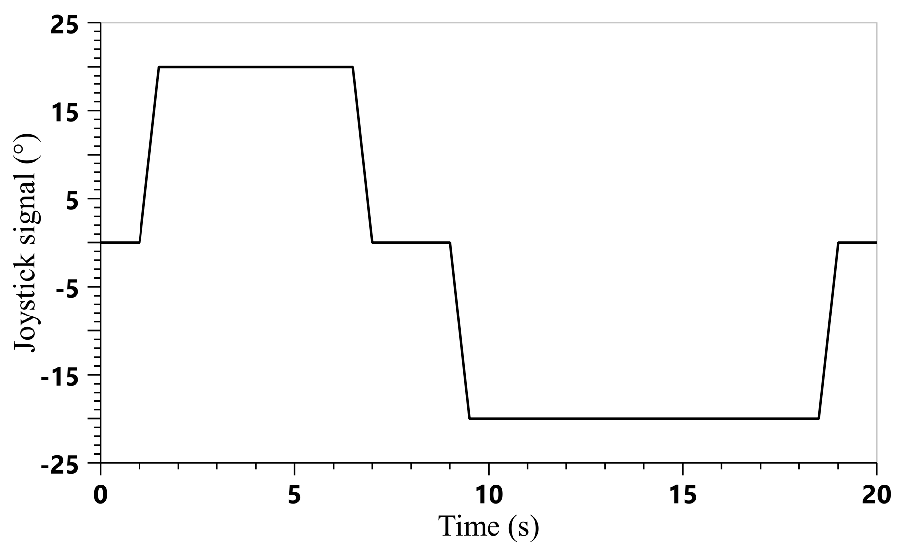
The cycle of the joystick is illustrated in Figure 8. Zero deg means the joystick stays in the neutral position; anything above zero deg means a lowering the signal of the boom for that time, whereas anything below zero deg means a lifting signal of the boom for that period, assuming that the other cylinders of the HE have no movements.
b)
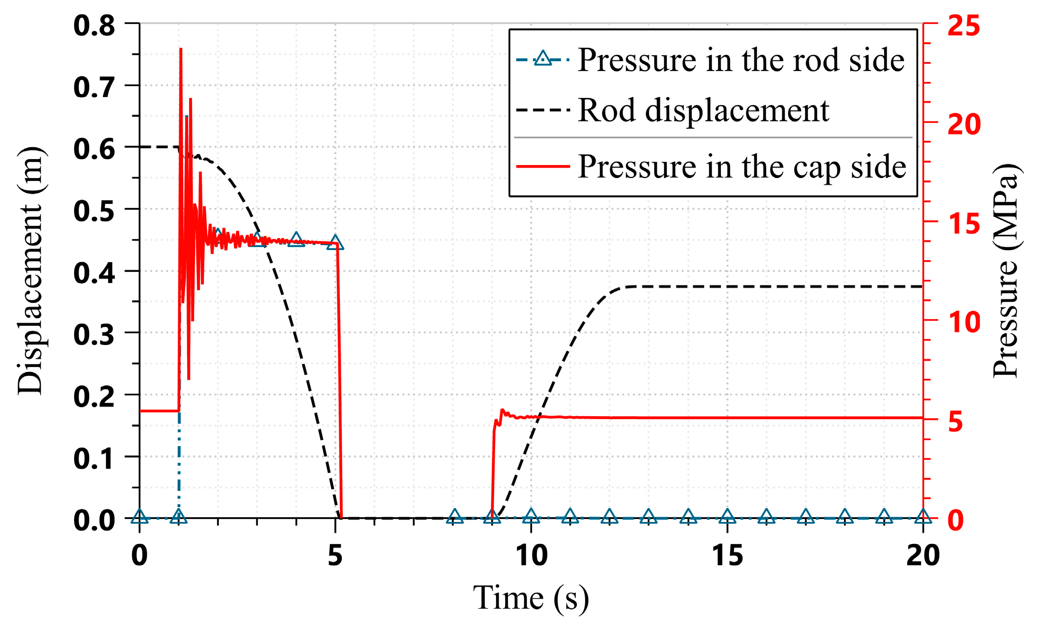
The retraction displacement of the boom cylinder in the simulation is 0.6 m.
Since the load does not vary in the simulation, the ratio of extension displacement to retraction displacement of the boom cylinder in a cycle is taken as an index to evaluate the energy-saving effect. The overall efficiency, η, is described as
η = s e s r
where se is the extension displacement of the boom cylinder by the recovered energy, m and sr is the retraction displacement of the boom cylinder during the descent, m.
Assume that the boom cylinder, the 2/2 directional control valve (see 7 in Figure 6) and the flywheel share the same efficiencies during the ascent and descent process, respectively. Similar to previous literatures [12,14], we focus on the energy efficiency of the energy recovery system. According to the order of energy transfer, the overall efficiency can be expressed by
η = η r η u = ( η c η v η m η f ) ( η c η v η p η f ) = η c 2 η v 2 η f 2 η m η p
where ηr and ηu are system efficiencies of the descent and ascent process; ηc is efficiency of the boom cylinder; ηv is the efficiency of the throttling valve; ηm and ηp are the efficiencies of PM when working in motoring and pumping mode; and ηf is the efficiency of the flywheel.
As the energy conversion component, the PM’s efficiency should be carefully studied. In one cycle, the PM delivers the energy two times, one in the pumping mode and another in the motoring mode. By referring to [46], the mathematical model can be obtained by fitting the efficiency data provided by the manufacturer. Figure 9 and Figure 10 describe the energy efficiency contours as the function of the normalized pressure difference and rotational speed in pumping and motoring mode while holding displacement constant, respectively. From these figures, it can be concluded that the efficiency varies little with changes in rotational speed. Since the rotational speed has little impact on efficiency, this paper focuses on the effects of the displacement and pressure on efficiency. Figure 11 and Figure 12 illustrate the pumping efficiency and motoring efficiency contours of the PM, respectively.
From Figure 11 and Figure 12, observe that enhancing working pressure is beneficial to energy efficiency. In pumping mode, when the working area of PM transfers from A to B, the pumping efficiency increases from 0.84 to 0.89. As for motoring mode, the efficiency increases from 0.81 to 0.88. In fact, specific mechanical efficiency and volumetric efficiency in terms of different operating conditions can be found in these figures. For simplification, fixed efficiency values of 0.83 for the FERS and 0.88 for the FFERS are adopted in the simulation model, although that will introduce a little deviation for the results. The efficiency data used in the simulation are found in Table 4.
As shown in Table 4, the introduction of flow regeneration brings many benefits to the system. Compared with the PM in the FERS, the PM displacement in the FFERS is reduced from 71 mL/rev to 28 mL/rev, a decrease of 71%. Furthermore, the total efficiency is promoted by 5%. In addition, the mass, the installation space, and the cost are reduced by 55%, 47%, and 35%, respectively. The maximum rotational speed increases by 36%, which prolongs the lifetime of the PM for a given working condition.
Since the flow rate of the PM is reduced, the pressure loss of the 2/2 directional control value is reduced; however, it is not discussed in this paper because of the limited effect on improving the energy efficiency of the system.

6.1. Working Performance of the FERS and FFERS

The boom cylinder displacement and the pressures in the two chambers of the FERS and the FFERS are displayed in Figure 13 and Figure 14, respectively. The rod side pressure in the FERS is omitted as it is always connected with the tank.
From Figure 13, it is observed that the initial boom cylinder piston position of the FERS is 0.6 m and the pressure in the cap side of the boom cylinder is about 5 MPa. The boom cylinder begins to retract at 1 s and retracts completely at approximately 4.9 s. In Figure 14, the initial boom cylinder piston position of the FFERS is the same as that of the FERS, and the initial pressure in the cap side of the boom cylinder. The boom cylinder retracts at 1 s and stops at 4.8 s, which means that the FFERS needs a little less time than the FERS. The primary reason is that a lower flow rate through the throttling valve produces less pressure drop. By observing the pressure curves, it is observed that the two chambers of the boom cylinder in the FFERS share the same pressure, about 14 MPa, owing to the direct connection with them. At the moment when the boom begins to move, the two chambers are connected instantaneously, and the effective working area of the boom cylinder decreases suddenly, causing a large pressure fluctuation. From 9 s, the boom cylinders begin to extend; the boom cylinder stops moving at about 11.5 s and 17 s, respectively.
Figure 15 and Figure 16 illustrate the rotational speeds of the flywheels and PMs. When the boom lowers, the flywheel accelerates and the rotational speed increases from zero to approximately 1700 rev/min. These indicate that the potential energy of the boom is transformed into the kinetic energy of the flywheel. There is a certain gap between the rotational speed and the theoretical value, which is caused by friction losses. The rotational speeds of the two flywheels drop from approximately 1650 rev/min to zero as the boom cylinders extend. That means the kinetic energy of the flywheel is again transformed into the potential energy of the boom. This verifies that the designed system can realize the recovery and reuse of the potential energy of the boom.
It can also be seen from Figure 15 and Figure 16, that, the rotational speed of the PMs coincides, most of the time, with the rotational speed of the flywheels. Once reaching the maximum rotational speeds, they begin to decrease due to the friction losses of the flywheels and the PMs. From 7 s to 9 s, the rotational speeds of the flywheels and the PMs are significantly different. The former still maintains a speed attenuation like that of the previous stage, but the latter’s rotational speed was greatly reduced. The reason is that, from 7 s, the clutch disengages the connection between the two. The speed of the flywheel is also decreasing, but showing a slower decline. However, the PM has a minor moment of inertia, and therefore the speed drops rapidly. Since the simulation time of the stage is only 2 s, the PM has not completely stopped, and the next stage starts. The swash plates swing to an opposite angle and the PM switches to pumping mode. At 9 s, the clutches are engaged again, and the flywheels begin to work as the power sources, and the PMs are driven to supply energy to the system to reuse of the recovered energy.
By comparing the above four figures, it is observed that the boom cylinder of FFERS needs more time for extension than that of the FERS. Shorter time means higher output power of the corresponding PM. There are at least two reasons responsible for this result. First, the original power system of the excavator is not considered in the simulation model, and therefore the flow rate of the original hydraulic system is missing. Secondly, for the boom system, the output power of the PM determines the extension speed of the corresponding boom cylinder. The output power of the PM is determined by the working pressure and the displacement of the PM and the rotational speed. The working pressures and the flywheel rotational speeds of the two systems are the same. Therefore, a larger PM outputs greater power. Therefore, the PM output power of FERS is much larger than that of the FFERS. The descent times of the two systems are similar because the effect of the higher working pressure compensates for that of the smaller PM in the FFERS. A possible way to enlarge the output power is by adopting a continuous variable transmission to change the rotational speed of the PM. Figure 17 describes a transmission ratio profile. The transmission ratio varies only when the flywheel discharges the recovered energy. The boom cylinder displacement and the pressures in the two chambers of the FFERS with varying transmission ratios are shown in Figure 18. Compared with Figure 14, the pressure curves are similar but the boom cylinder needs less time for extension. The extension time is reduced from 8 s to 3.4 s, which is still longer than that of the FERS, but acceptable. This is contributed by the transmission. Figure 19 describes the rotational speeds of the flywheel and PM of the FFERS. A similar conclusion can be drawn from Figure 19. By using a varying transmission ratio, the FFERS can get a similar working efficiency as the FERS. It is concluded that the working efficiency can be adjusted to a desired range by changing the transmission ratio profile.
Another bone of contention is the manufacturing costs [47]. Adding a continuous variable transmission increases the manufacturing cost. Many researchers point out that the price of a flywheel is higher than that of a battery because the flywheel is typically a small batch production. But others reported that the total cost of using a flywheel ERS is less than using a battery ERS [48,49,50]. One thing that cannot be ignored is the expensive power electronics of the battery ERS. There are also other cheaper alternatives for continuous variable transmissions, such as using a brake-actuated planetary gear system [51], a fixed ratio gearbox with a slipping clutch [52], or a gearbox with a few steps plus a smaller gearbox [53]. However, this results in a lower energy efficiency than using a continuous variable transmission [54]. In summary, there is a compromise between improving energy efficiency and increasing the total cost which is highly dependent on design.

6.2. Realization of Flow Regeneration Function

Figure 20 displays the flow rates of the PM and the two chambers of the boom cylinder of the FFERS. Since the flow regeneration function only works as the boom lowers, only the data of this phase is displayed.
In Figure 20, the flow rate of the cap side chamber is exactly equal to the sum of the flow rate of the rod side chamber and the flow rate of the PM. This means that the flow regeneration function can be achieved normally, and reduce the flow rate through the PM, and thus reducing the size. This is also consistent with the previous analysis and calculations. The reason for the fluctuation of the curve is the same as the reason for the pressure fluctuation in Figure 14. Note that the flow rate of the PM did not drop to zero till 7 s. The reason is that the PM swash plate does not return to the neutral position, refer to Figure 19. As previously mentioned, the flow is supplemented via the check valve. At 7 s, the swash plate of the PM swings to the neutral position and the flow rate is reduced to zero. It can be deduced that in a real system when the boom stops moving, the swing angle of the PM should be controlled to the neutral position as soon as possible to prevent cavitation. The flow rate in the FERS is not examined since there is no flow regeneration function.

6.3. Influence of PM Displacement on System Performance

PM is the energy conversion component of the system, and the displacement is a crucial parameter in the energy-saving characteristics of the system. Analysis shows that under the same conditions, the larger the PM, the more powerful the driving capacity is, and the larger the acceleration and deceleration of the flywheel are, and vice versa. However, from the point of view of design and manufacturing, a larger PM means higher cost and greater weight, and more installation space is needed.
Three set (no. 1, 2, and 3) of simulations were conducted with the displacement values of 18 mL/rev, 23 mL/rev, and 28 mL/rev set for PM, respectively. The corresponding inertia parameters are given in Table 5. There is no ready 23 mL/rev size PM in the product sheet, but it can be gotten by adjusting the actual displacement of a 28 mL/rev size PM. Hence, all the parameters of the 23 mL/rev PM and the 28 mL/rev PM will be the same but not the displacement. The influence of the PM displacement on the boom cylinder speed and the energy recovery effect is studied, as illustrated in Figure 21 and Figure 22.
From Figure 21, it is concluded that the boom speed increases with the PM displacement. When the displacement of the PM is 18 mL/rev, 23 mL/rev, and 28 mL/rev, the descent times are 4.8 s, 2.7 s, and 3.1 s, and the ascent time is 5.5 s, 3.4 s, and 2.8 s, respectively. With the displacement of the PM decreased, the boom height increased, as shown in the inset of Figure 21. This indicates that more energy is recovered when using a larger PM, which means higher energy efficiency. Similar conclusions can be drawn by observing the rotational speed curves in Figure 22. Figure 23 illustrates the energy stored in the flywheel. In Figure 22, the rotational speeds of the flywheel increase as the boom lowers, meanwhile the boom potential energy is converted into the kinetic energy of the flywheel. When the boom cylinder fully retracts, the flywheel reaches the maximum rotational speed. Then, the flywheel continues to rotate and switch to a standby mode, but the speed will slow down due to friction. One can get similar conclusion from Figure 23. By using Equation (14), the energy recovery and reuse efficiency of the FFERS is 13% higher than that of the FERS, as is given in Table 6. Specifically, it is 62% for the FFERS as compared with 55% for the FERS.
There are at least two main reasons why the FFERS has higher energy efficiency than the FERS. One reason is that the PM of the FFERS works in a more efficient zone as compared with that of the FERS. Another reason is that a reduction of flow rate yields a lower pressure loss through valves and piping.
In summary, within an acceptable range of the boom speed, the displacement, the installation space, and the mass of the PM are reduced by a large margin by introducing flow regeneration, which is beneficial to improve energy utilization efficiency and also advantageous for reducing the manufacturing cost and weight of the equipment.

7. Conclusions

A novel energy recovery system integrating flywheel and flow regeneration for HE booms is proposed in this paper. The system not only recovers boom potential energy by employing a flywheel but also achieves a flow regeneration function by introducing an auxiliary valve. The latter improves the energy recovery through enhancing the working pressure and a reduced flow rate, which is verified by both analytical and numerical comparisons of the FFERS (with flow regeneration function) and the FERS (without flow regeneration function). The comparison with a FERS shows that the PM displacement in the FFERS is reduced by 71%, from 71 mL/rev to 28 mL/rev. It also provides the possibility of downsizing other components, such as relevant valves and piping and cutting costs. Considering the friction loss of the boom cylinder, the efficiency of the PM and frictional losses of the flywheel, the maximum overall efficiency of the proposed FFERS is 13% higher than that of the FERS, and this can reach up to 62% for a 4 t excavator. By contrast, the FERS can reach up to 55%. In summary, significant energy saving can be achieved by the proposed system. However, one limitation of this simulation model presented here makes assumptions that oversimplify the situation. To fully understand the energy recovery system, a more advanced model is required that removes the oversimplified assumptions. Note that using a PM with smaller displacement could lead to low working efficiency when reusing the energy recovered. As a possible solution, employing a continuous variable transmission is proposed, which possesses a drawback of adding cost and system complexity. Compared with the conventional boom system, this system needs a more complex control system. In conclusion, more cost analysis needs to be carried out when designing a system and a tradeoff should be made among cost, energy-saving effect, and working efficiency.
In future work, the effects of flywheel energy recovery on system controllability, optimization of flywheel energy efficiency, and working efficiency are worth studying.

8. Patents

J. Li, W. Zhang. Electrohydraulic control system for potential energy recovery and reutilization for construction machinery boom. CN: CN108180188A, 19 June 2018.

Author Contributions

Conceptualization, J.L. and J.Z.; methodology, J.L.; software, X.Z.; validation, J.L. and X.Z.; investigation, J.L. and X.Z.; writing—original draft preparation, J.L.; writing—review and editing and supervision, and project administration, J.Z.; funding acquisition, J.L. and J.Z. All authors have read and agreed to the published version of the manuscript.

Funding

This work was funded by the Jiangsu Overseas Visiting Scholar Program for the University Prominent Young & Middle-aged Teachers and Presidents 2018, the Xuzhou College of Industrial Technology Science and Technology Foundation under grant XGY2017EA01, and the Jiangsu Science and Technology Association Youth Science and technology talent lifting project.

Conflicts of Interest

The authors declare no conflict of interest.

References

  1. Kagoshima, M.; Komiyama, M.; Nanjo, T.; Tsutsui, A. Development of new hybrid excavator. Kobelco Technol. Rev. 2007, 27, 39–42. [Google Scholar]
  2. Li, S.; Wei, J.; Fang, J.; Guo, K.; Liu, W. Design and Control of Hydraulic Hybrid System for Excavators. In Proceedings of the ASME/BATH 2015 Symposium on Fluid Power and Motion Control, Chicago, IL, USA, 12–14 October 2015. [Google Scholar] [CrossRef]
  3. Chen, M.; Zhao, D. The gravitational potential energy regeneration system with closed-circuit of boom of hydraulic excavator. Mech. Syst. Signal Process. 2017, 82, 178–192. [Google Scholar] [CrossRef]
  4. Lin, T.; Chen, Q.; Ren, H.; Huang, W.; Chen, Q.; Fu, S. Review of boom potential energy regeneration technology for hydraulic construction machinery. Renew. Sustain. Energy Rev. 2017, 79, 358–371. [Google Scholar] [CrossRef]
  5. Mathews, T.; Nishanth, D. Flywheel based kinetic energy recovery systems (KERS) integrated in vehicles. Int. J. Eng. Sci. Technol. 2013, 5, 1694–1699. [Google Scholar]
  6. Chen, Q.; Lin, T.; Ren, H. A Novel Control Strategy for an Interior Permanent Magnet Synchronous Machine of a Hybrid Hydraulic Excavator. IEEE Access 2018, 6, 3685–3693. [Google Scholar] [CrossRef]
  7. Bauman, J.; Kazerani, M. A comparative study of fuel-cell-battery, fuel-cell–ultracapacitor, and fuel-cell-battery–ultracapacitor vehicles. IEEE Trans. Veh. Technol. 2008, 57, 760–769. [Google Scholar] [CrossRef]
  8. Kanezawa, Y.; Daisho, Y.; Kawaguchi, T. Increasing efficiency of construction machine by hybrid system. In Proceedings of the JSAE (Society of Automotive Engineers of Japan) Annual Congress, Tokyo, Japan, 23–25 May 2001; pp. 17–20. [Google Scholar]
  9. Wang, Q. Research on key technology of oil-electric hybrid excavator. J. Mech. Eng. 2013, 49, 123–129. [Google Scholar] [CrossRef]
  10. Wang, T.; Wang, Q. An energy-saving pressure-compensated hydraulic system with electrical approach. IEEE ASME Trans. Mech. 2013, 19, 570–578. [Google Scholar] [CrossRef]
  11. Lin, T.; Wang, Q.; Hu, B.; Gong, W. Development of hybrid powered hydraulic construction machinery. Autom. Constr. 2010, 19, 11–19. [Google Scholar] [CrossRef]
  12. Lin, T.; Wang, Q.; Hu, B.; Gong, W. Research on the energy regeneration systems for hybrid hydraulic excavators. Autom. Constr. 2010, 19, 1016–1026. [Google Scholar] [CrossRef]
  13. Chen, Q.; Lin, T.; Ren, H.; Fu, S. Novel potential energy regeneration systems for hybrid hydraulic excavators. Math. Comput. Simul. 2019, 163, 130–145. [Google Scholar] [CrossRef]
  14. Yu, Y.; Ahn, K. Optimization of energy regeneration of hybrid hydraulic excavator boom system. Energy Convers. Manag. 2019, 183, 26–34. [Google Scholar] [CrossRef]
  15. Minav, T.A.; Virtanen, A.; Laurila, L.; Pyrhönen, J. Storage of energy recovered from an industrial forklift. Autom. Constr. 2012, 22, 506–515. [Google Scholar] [CrossRef]
  16. Minav, T.; Hänninen, H.; Sinkkonen, A.; Laurila, L.; Pyrhönen, J. Electric or hydraulic energy recovery systems in a reach truck—A comparison. Stroj. Vestn. J. Mech. Eng. 2014, 60, 232–240. [Google Scholar] [CrossRef]
  17. Hannan, M.A.; Hoque, M.M.; Mohamed, A.; Ayob, A. Review of energy storage systems for electric vehicle applications: Issues and challenges. Renew. Sustain. Energy Rev. 2017, 69, 771–789. [Google Scholar] [CrossRef]
  18. Bruun, L. Swedish developed energy saving system in Caterpillars excavators. Fluid Scand. 2002, 2, 6–9. [Google Scholar]
  19. Hao, Y.; Quan, L.; Cheng, H.; Xia, L.; Ge, L.; Zhao, B. Potential energy directly conversion and utilization methods used for heavy duty lifting machinery. Energy 2018, 155, 242–251. [Google Scholar] [CrossRef]
  20. Xia, L.; Quan, L.; Ge, L.; Hao, Y. Energy efficiency analysis of integrated drive and energy recuperation system for hydraulic excavator boom. Energy Convers. Manag. 2018, 156, 680–687. [Google Scholar] [CrossRef]
  21. Zhao, P.; Chen, Y.; Zhou, H. Simulation analysis of potential energy recovery system of hydraulic hybrid excavator. Int. J. Precis. Eng. Manuf. 2017, 18, 1575–1589. [Google Scholar] [CrossRef]
  22. Liang, X.; Virvalo, T. An energy recovery system for a hydraulic crane. Proceedings of the Institution of Mechanical Engineers. J. Mech. Eng. Sci. 2001, 215, 737–744. [Google Scholar] [CrossRef]
  23. Zhang, S.; Minav, T.; Pietola, M. Decentralized Hydraulics for Micro Excavator. In Proceedings of the 15th Scandinavian International Conference on Fluid Power, Linköping, Sweden, 7–9 June 2017. [Google Scholar] [CrossRef] [Green Version]
  24. Zhao, D.; Chen, D.; Dai, Q.; Zhang, E.; Xu, C. System of arm potential energy recovery in hybrid hydraulic excavators. J. Jilin Univ. Eng. Technol. Ed. 2011, 41, 150–154. [Google Scholar] [CrossRef]
  25. Pettersson, K.; Heybroek, K.; Klintemyr, A.; Krus, P. Analysis and control of a complementary energy recuperation system. In Proceedings of the 8th International Fluid Power Conference, Dresden, Germany, 26–28 March 2012. [Google Scholar]
  26. Shen, W.; Jiang, J.; Su, X.; Karimi, H. Control strategy analysis of the hydraulic hybrid excavator. J. Frankl. Inst. 2015, 352, 541–561. [Google Scholar] [CrossRef]
  27. Jing, J.; Quan, L.; Huang, J.; Zhao, B. Research on the characteristics of asymmetric pump directed controlled arm cylinder of excavator. J. Mech. Eng. 2016, 52, 188–196. [Google Scholar] [CrossRef]
  28. Hebner, R.; Beno, J.; Walls, A. Flywheel batteries come around again. IEEE Spectr. 2002, 39, 46–51. [Google Scholar] [CrossRef] [Green Version]
  29. Hedlund, M.; Lundin, J.; Santiago, J.; Abrahamsson, J.; Bernhoff, H. Flywheel Energy Storage for Automotive Applications. Energies 2015, 8, 10636–10664. [Google Scholar] [CrossRef] [Green Version]
  30. Cronk, P.; Ven, J. A review of hydro-pneumatic and flywheel energy storage for hydraulic systems. Int. J. Fluid Power 2017, 1, 1–11. [Google Scholar] [CrossRef]
  31. Amirante, R.; Cassone, E.; Distaso, E.; Tamburrano, P. Overview on recent developments in energy storage: Mechanical, electrochemical and hydrogen technologies. Energy Convers. Manag. 2017, 132, 372–387. [Google Scholar] [CrossRef]
  32. Dhand, A.; Pullen, K. Review of flywheel based internal combustion engine hybrid vehicles. Int. J. Automot. Technol. 2013, 14, 797–804. [Google Scholar] [CrossRef] [Green Version]
  33. Arani, A.K.; Karami, H.; Gharehpetian, G.B.; Hejazi, M.S. Review of flywheel energy storage systems structures and applications in power systems and microgrids. Renew. Sustain. Energy Rev. 2017, 69, 9–18. [Google Scholar] [CrossRef]
  34. Ebadi, A.; Ji, J. Investigation & comparison of the integration of flywheel energy storage in hybrid electric and electric vehicles using bond graphs. In Proceedings of the 20th International Conference on Electrical Machines and Systems (ICEMS), Sydney, Australia, 11–14 August 2017. [Google Scholar] [CrossRef]
  35. Spiryagin, M.; Wolfs, P.; Szanto, F.; Sun, Y.; Cole, C. Application of flywheel energy storage for heavy haul locomotives. Appl. Energy 2015, 157, 607–618. [Google Scholar] [CrossRef]
  36. Volvo Car UK. Volvo Car Group and Flybrid Conduct Uk Testing of Flywheel Kers Technology. 2014. Available online: https://www.media.volvocars.com/uk/en-gb/media/pressreleases/141626/volvo-car-group-andflybrid-conduct-uk-testing-of-flywheel-kers-technology (accessed on 5 June 2019).
  37. Mousavi, S.M.; Faraji, F.; Majazi, A.; Al-Haddad, K. A comprehensive review of Flywheel Energy Storage System technology. Renew. Sustain. Energy Rev. 2017, 67, 477–490. [Google Scholar] [CrossRef]
  38. Ricardo. Ricardo to Showcase ‘TorqStor’ High Efficiency Flywheel Energy Storage at CONEXPO. Available online: https://ricardo.com/news-and-media/news-and-press/ricardo-to-showcase-%E2%80%98torqstor%E2%80%99-high-efficiency-fly (accessed on 4 December 2019).
  39. Choi, K.; Seo, J.; Nam, Y.; Kim, K. Energy-saving in excavators with application of independent metering valve. J. Mech. Sci. Technol. 2015, 29, 387–395. [Google Scholar] [CrossRef]
  40. WANG, Y.; Quan, L.; Li, A. Boom Lifting Control Scheme of Large Mining Hydraulic Excavator. J. Mech. Eng. 2013, 49, 161–166. [Google Scholar] [CrossRef]
  41. Li, J.; Zhao, J.; Xing, H.; Zhang, X.; Jin, Y. Research on Flywheel Based Energy Recovery System for Hydraulic Excavator Boom. In Proceedings of the 8th International Conference on Fluid Power and Mechatronics, Wuhan, China, 10–13 April 2019. [Google Scholar]
  42. Kousksou, T.; Bruel, P.; Jamil, A.; El Rhafiki, T.; Zeraouli, Y. Energy storage: Applications and challenges. Sol. Energy Mater. Sol. Cells 2014, 120, 59–80. [Google Scholar] [CrossRef]
  43. Buchroithner, A.; Haidl, P.; Birgel, C.; Zarl, T.; Wegleiter, H. Design and experimental evaluation of a low-cost test rig for flywheel energy storage burst containment investigation. Appl. Sci. 2018, 8, 2622. [Google Scholar] [CrossRef] [Green Version]
  44. Wicki, S.; Hansen, E. Clean Energy Storage Technology in the Making: An Innovation Systems Perspective on Flywheel Energy Storage. J. Clean Prod. 2017, 162, 1118–1134. [Google Scholar] [CrossRef] [PubMed]
  45. Bosch Rexroth. Pressure and Flow Control System SYDFED-2X. Available online: https://www.boschrexroth.com/ics/cat/?cat=Industrial-Hydraulics-Catalog&m=DE&u=si&o=Desktop&p=p770607&pi=3E000602-D83B-2699-6B9A5491BC66AA3A_ICS_82 (accessed on 10 June 2019).
  46. Cornell, C. Dynamic simulation of a hydrostatically propelled vehicle. SAE Trans. 1981, 3903–3923. [Google Scholar] [CrossRef]
  47. Buchroithner, A.; Wegleiter, H.; Schweighofer, B. Flywheel Energy Storage Systems Compared to Competing Technologies for Grid Load Mitigation in EV Fast-Charging Applications. In Proceedings of the 27th International Symposium on Industrial Electronics, Cairns, Australia, 13–15 June 2018. [Google Scholar] [CrossRef]
  48. Kapoor, R.; Parveen, C.M. Comparative study on various KERS. In Proceedings of the World Congress on Engineering, London, UK, 3–5 July 2013. [Google Scholar]
  49. Druten, R.M. Transmission Design of the Zero Inertia Powertrain. Ph.D. Thesis, Technische Univ. Eindhoven, Eindhoven, The Netherlands, 2001. [Google Scholar] [CrossRef]
  50. Hilton, J. Flybrid systems—Mechanical hybrid systems. In Proceedings of the Engine Expo 2008, Stuttgart, Germany, 6–8 May 2008. [Google Scholar]
  51. Diego-Ayala, U.; Martinez-Gonzalez, P.; McGlashan, N.; Pullen, K.R. The mechanical hybrid vehicle: An investigation of a flywheel-based vehicular regenerative energy capture system. Proc. Inst. Mech. Eng. Part D J. Autom. Eng. 2008, 222, 2087–2101. [Google Scholar] [CrossRef]
  52. Deakin, A.J. Low Carbon Vehicle Event 2015. High Performance and Low CO2 from a Flybrid® Mechanical Kinetic Energy Recovery System. Available online: http://past.cenex-lcv.co.uk/2015/assets/downloads/lcv2015-presentations/seminar-dome-pm-svt/andrew-deakin.pdf (accessed on 10 September 2019).
  53. Read, M. Flywheel Energy Storage Systems for Rail. Ph.D. Thesis, Imperial College London, London, UK, 2010. [Google Scholar] [CrossRef]
  54. Read, M.; Smith, R.A.; Pullen, K.R. Optimisation of flywheel energy storage systems with geared transmission for hybrid vehicles. Mech. Mach. Theory 2015, 87, 191–209. [Google Scholar] [CrossRef]
Figure 1. Schematic of hydraulic excavator boom system equipped with an electrical energy recovery system.
Energies 13 00315 g001
Figure 2. Schematic of hydraulic excavator equipped with the hydraulic energy recovery system.
Energies 13 00315 g002
Figure 3. Automobile application schematic of the flywheel-based energy recovery system.
Energies 13 00315 g003
Figure 4. Schematic of the flow regeneration system.
Energies 13 00315 g004
Figure 5. Configuration of the flywheel energy recovery system (FERS) for the hydraulic excavator (HE) boom: 1, engine; 2, pump; 3, directional control valve; 4, boom cylinder; 5, reservoir; 6, hydraulic pump motor; 7, 2/2 directional control valve; 8, flywheel; 9, clutch; 10, safety valve; 11, check valve; 12, controller; and 13, joystick.
Energies 13 00315 g005
Figure 6. Configuration of the novel compound energy recovery system integrating flywheel and flow regeneration (FFERS) for the HE boom: 1, engine; 2, pump; 3, directional control valve; 4, boom cylinder; 5, reservoir; 6, hydraulic pump motor; 7, 2/2 directional control valve; 8, flywheel; 9, clutch; 10, safety valve; 11, check valve; 12, controller; 13, joystick; 14, flow regeneration valve; and 15, gearbox.
Energies 13 00315 g006
Figure 7. The simulation model established in AMESim software.
Energies 13 00315 g007
Figure 8. Cycle of the boom joystick.
Energies 13 00315 g008
Figure 9. Efficiency contours of the pump motor (PM) as a function of the normalized pressure difference and rotational speed in pumping mode: (a) the whole view and (b) enlarged view of area 1.
Energies 13 00315 g009
Figure 10. Efficiency contours of the PM as a function of the normalized pressure difference and rotational speed in motoring mode: (a) the whole view and (b) enlarged view of area 2.
Energies 13 00315 g010
Figure 11. Efficiency contours as a function of the normalized pressure difference and displacement in pumping mode.
Energies 13 00315 g011
Figure 12. Efficiency contours as a function of the normalized pressure difference and displacement in motoring mode.
Energies 13 00315 g012
Figure 13. The boom cylinder displacement and the pressures of the boom cylinder of FERS.
Energies 13 00315 g013
Figure 14. The boom cylinder displacement and the pressures of the boom cylinder of the FFERS.
Energies 13 00315 g014
Figure 15. The rotational speeds of the flywheel and PM of FERS.
Energies 13 00315 g015
Figure 16. The rotational speeds of the flywheel and PM of the FFERS.
Energies 13 00315 g016
Figure 17. The varying transmission ratio.
Energies 13 00315 g017
Figure 18. The boom cylinder piston displacement and the pressures in the two chambers of the boom cylinder for the FFERS with a variable transmission ratio.
Energies 13 00315 g018
Figure 19. The rotational speeds of the flywheel and PM of the FFERS with a variable transmission ratio.
Energies 13 00315 g019
Figure 20. The flow rates of the boom cylinder and PM when the FFERS works in the energy recovery mode.
Energies 13 00315 g020
Figure 21. Displacements of the boom cylinder at different PM displacements.
Energies 13 00315 g021
Figure 22. Rotational speeds of the flywheel at different PM displacements.
Energies 13 00315 g022
Figure 23. Energy stored in the flywheel at different PM displacements.
Energies 13 00315 g023
Table 1. The outline of typical construction machinery with different types of energy recovery systems.
AuthorsYearERS TypeStorage CapacityEnergy SavingsComments
Kanezawa [8]2001Electrical-35%First, study the application of energy recovery technology in construction machinery.
Wang [10]2013ElectricalUltracapacitor, 7.5 F, 0–400 V17%An electrical ERS is used to realize pressure compensation and energy recovery.
Lin [12]2012ElectricalUltracapacitor, 7.5 F, 0–400 V41%An accumulator is used as temporary energy storage component.
Chen [13]2019ElectricalUltracapacitor, 40 F, 280–420 V58%
Yu [14]2019ElectricalBattery33.8% to 57.4%The hydraulic motor is installed between the cylinder and the main valve.
Minav [15,16]2012ElectricalBattery and ultracapacitor
63 F, 125 V
54%They provided analyses of different ERSs from the energy efficiency perspective based on a forklift.
Bruun [18]2002HydraulicAccumulator37%A motor and a transition cylinder are used to charge the accumulator.
Quan [19,20]2018HydraulicAccumulator, 240 L; 20 L49.1% and 70.9%Adding a counterbalance cylinder to the baseline system or using a three-chamber cylinder instead of a conventional one.
Zhou [21]2017HydraulicAccumulator, 10 L, 50 L, and 100 LUp to 50%A scheme of the closed hydraulic system of excavator using a three-chamber hydraulic cylinder and accumulator.
Liang [22]2001HydraulicAccumulator18%Based on a crane with load sensing system.
Minav [16]2014HydraulicAccumulator, 4 L45%-
Zhang [23]2017HydraulicAccumulator50%A concept of direct driven hydraulics drive is proposed.
Table 2. Parameters of the boom cylinder of a 4 t HE.
ComponentParametersValue
Boom cylinderPiston diameter [mm]90
Rod diameter [mm]53
Stroke [m]0.6
Number of cylinders1
Maximum recyclable energy [kJ]22.6
Table 3. Pertinent simulation parameters.
ComponentParametersValue
Boom cylinderPiston diameter (mm)90
Rod diameter (mm)53
Stroke (m)0.6
Viscous friction coefficient [N/(m/s)]800
Stiction force (N)600
Coulomb friction force (N)600
FlywheelMoment of inertia kg m2)1.03
Viscous damping coefficient [N·m/(rev/min)]0.001
Table 4. Simulation parameters of PMs in FERS and FFERS.
ParametersFERS 1FFERS 2UnitsImprovement
Maximum displacement 7128mL/rev71%
Mass43.319.3kg55%
Moment of inertia0.00830.0017kg m2N.A.
Maximum rotational speed22003000rev/min36%
Mechanical efficiency0.870.95-8%
Volumetric efficiency0.950.93-−2%
Total efficiency0.830.88-5%
Dimensions L × W × H426 × 301 × 404378 × 235 × 310mm47%
Price34002200$35%
1 FERS, flywheel-based energy recovery system; 2 FFERS, compound energy recovery system integrating flywheel and flow regeneration.
Table 5. Simulation parameters of PM for the FFERS.
No.Displacement (mL/rev)Mass (kg)Nominal Rotational Speed [rev/min]Moment of Inertia (kg m2)
11819.333000.00093
22322.330000.0017
328
Table 6. Comparison of energy efficiencies of the FERS and FFERS.
NameUpward Displacement of Boom Cylinder (m)Downward Displacement of Boom Cylinder (m)Overall Efficiency (%)Energy Efficiency Improvement
FERS 10.3320.655-
FFERS 20.3756213%
1 FERS, flywheel-based energy recovery system and 2 FFERS, compound energy recovery system integrating flywheel and flow regeneration.

