Abstract
As the world population is increasing rapidly, food and water demands are the most crucial problem for humanity. In some areas of the world, water or environment is unsuitable for plant growth; hydroponic systems can provide a suitable environment for crop production with effective management of natural resources. Internet of Things paradigm based automated systems has been creating an excellent opportunity for monitoring and controlling agriculture by minimizing the cost and maximizing the profit significantly over the past decade. The reduction of the cost can be achieved by sufficient usage of resources and setting up optimum operational parameters for agricultural devices. This paper presents an optimization scheme with novel objective function for hydroponics environment parameters management with efficient energy consumption. The proposed approach provides optimal energy and resource utilization in the hydroponics system with setting up a working level and operational duration to the actuators. We have developed an optimization scheme with objective function for optimal humidity and water level control based on fuzzy logic, which can support the optimal measurement for crop growth with energy efficiency. Fuzzy logic control is applied for the compromise between actuators working level and operational duration. A real hydroponics environment has been implemented and presented to evaluate the effectiveness of the proposed approach. It can be assessed through the simulation results that the optimization module achieves a signification reduction (18%) in energy consumption as compared to the other scheme.
1. Introduction
Statistics show that the current population of the world is predicted to reach 8.5 billion by 2030 and 11.2 billion in 2100 years [1]. As the population is increasing continuously, demands for food and water will also grow. Seventy percent of the earth’s surface is covered with water, so the “Blue Planet” term is used for our planet. It seems water source is abundant on the earth, however, only 0.3% of water can be consumed by humans. The remaining 99.7% is in oceans, icecaps and not acceptable for drinking or irrigation [2]. Providing future generation with these natural products are full of doubts and concern their sustainability and performance. There are various reasons that can impact food production and water resources such as population growth, climate change, natural disasters, unmanaged consumption of natural resources and to name a few [3]. International organizations, societies, institutions, researchers and individuals should work collaboratively to find out practical solutions in both agricultural and aquaculture science to develop alternative scenarios for overcoming water and food problems. The hydroponics environment is one of the highlighted solutions for the issues mentioned above. Hydroponics is a plant production in nutrient solutions with or without the utilization of an inert medium such as rock wool, saw and coir dust, coconut fiber and gravel for providing a solid base [4]. Ancient Greeks created a hydroponics system since the meaning of the hydroponics term is the combination of Greek words “hydro” (water) and “ponos” (work) [5,6]. Hydroponic techniques for plant production started from the late 1920s, and in the 1940s, it began to use in commercial-scale widely [7,8].
As the demand for food and water increases in terms of quantity and quality, the requirement for industrializing agricultural practices has also increased. Internet of Things (IoT) is a paradigm that can influence not only our daily life with considerable benefits but also offers many solutions for agricultural modernization. IoT is becoming more and more pervasive in our daily life. Various devices such as sensors, Raspberry Pi and microcontrollers are interconnect with each other and provide smart services to users [9]. Currently, more than 9 billion IoT devices are being utilized in our daily life, and it is expected to increase more than 26 billion devices by 2020 [10]. Among the application scenarios for the IoT, we can find smart buildings, smart cars, smart cities, building automation, environmental monitoring and smart farming. IoT based applications can create systems for improving overall system efficiency, automatization processes, accuracy and maximizing total income in a variety of fields [11]. Similar to water and food, electricity is also considered a unique resource in modern society. Increasing demands for electrical power is motivating companies and industries to produce more and more electrical energy [12]. US-Energy Information Administration (EIA) statistics show that until 2040 the global demand for energy is expected to expand to 28% [13].
With this paper, we have proposed an optimization scheme based on the fuzzy logic control module for the hydroponics system in the IoT environment. Our proposed approach can provide optimal water and humidity level according to the user/farmer desired settings for effective plant productivity with efficient energy consumption. Additionally, the required water and humidity level are automatically compromised between actuators’ working level and operational duration to maximize profit. The proposed system includes embedded devices such as water and humidity level sensors, four types of actuators, namely, water pump, overflow system, dehumidifier and a fogging system.
The system consists of modules such as the data acquisition process, optimization module, and fuzzy logic control module. Hydroponics systems are usually installed in the indoor environment since manual controlling the temperature, CO2 level, pH is not a big issue in the indoor condition [14]. However, water level and humidity are needed simultaneously for optimal control in indoor; as a consequence, we have developed the system by considering the water and humidity level of the hydroponics parameters. The design and the objective function of the system are adaptable to other types of sensor parameters, such as temperature, oxygen, CO2 level and pH, because of its flexibility. The data acquired from sensors are stored in the server where it is analyzed and optimal decisions are made accordingly. The communication protocol in this work is used as Hypertext Transfer Protocol (HTTP) to avoid additional translation functions [15,16,17]. The data acquired are applied to the optimization and control units in order to select the optimal working level and operational duration to the actuators. The proposed optimization and fuzzy logic based smart hydroponics environment are designed and implemented successfully as an experimental environment.
The rest of the paper is organized as follows. Section 2 includes the related works, which consist of the hydroponics system working principles, IoT and optimization scheme-based hydroponics models. Section 3 illustrates the proposed hydroponics system design and the detailed formulation of the proposed optimization scheme. Detail fuzzy logic control module methodology is described in in Section 4. Section 5 describes the experimental setup and performance evaluation results are given in Section 6. Section 7 includes the comparison and significance of the proposed system with the existing system. Finally, Section 8 includes the conclusion and future work.
2. Related Works
Growing vegetables and crops in the greenhouse are one of the most exciting and intensive methods of all agricultural business. As well as the greenhouse method, the hydroponics system is also being popular, mainly in Canada, the USA, Japan and in European countries. It is highly productive technology, conservative of land and water as well as protective of the environment. Depending on the working structure, six basic types of hydroponics systems are available: wick system, deep water culture, the technology of nutrient films, aeroponics, drip irrigation system and the ebb and flow hydroponics system [18]. Different types of hydroponics systems are configured based on environment and type of plant, for instance, deep flow hydroponics system is universal for herbs and leafy vegetable production. Rockwool and perlite are utilized for growing cucumber, tomato, pepper and so on [19]. Ebb and Flow systems are commonly used among growers because this system is easy to build, control and manage resources [20]. Currently, computers operate numbers of devices in greenhouses and hydroponics for analyzing different external and internal parameters, to provide the most acceptable environment to healthy plant production [21]. These input parameters include temperature, humidity, CO2, lights and the water level, which are essential parameters for faster and healthy plant production [22]. If these parameters are maintained with optimal levels, the plant should grow effectively compare to its natural growth. IoT devices can provide an excellent opportunity to create a healthy crop production environment and real-time control of hydroponics farming. The utilization of IoT devices can regulate the management of temperature, light, water level and pH. For example, in winter, water can freeze and influence the plant growth process. Water temperature sensors in the hydroponics farm can detect the temperature level and send notifications to the farmers [23].
Ludwig et al. [24] did some researches on monitoring the hydroponics environment through IoT devices. The authors controlled conductivity level, the pH and brightness of the hydroponics system; microcontroller was utilized for collecting all of the data. The microcontroller displays the status of the current condition of the parameters mentioned above and uses relay switches to control the lighting system through the controllers. Another research to the automatic hydroponics system is a do-it-yourself application that can be installed to both Android/iOS-based devices for monitoring the environment through the Internet from any place [25]. This application includes touch controls to adjust the hydroponic installation for a variety of sensors, namely, humidity, temperature and lighting level. One of the best sides of this application is saving data about planning, quick management and harvesting process information. This information received through sensors are stored in the cloud. For the automatization case, they utilized machine learning algorithms to the system with IoT devices. In one study, authors built a Bayesian network for checking the environment of a hydroponic system through IoT devices for light, pH, conductivity, water supplement level and humidity level [26]. The sensing values were utilized to configure the Bayesian network for performing future decision with the selection of the best environment automatically for managing the system. Visualization of the sensor values and actuators’ configuration parameters can be monitored through the graphical user interface.
IoT based hydroponics system prototype has been suggested by Gosavi [27]. Water level and luminosity and pH are monitored by configuring electrical conductivity, lumens meter and water level sensors. Sensing values are forwarded to the ARM7 Microcontroller, this module has a decision making unit for computing optimal growth environment to the plants based on current sensing parameters. If we take light control of the hydroponics environment as an example, the plant is required to be under light for 16 h, and in the dark for 8 h. So, the microcontroller includes a real-time clock function, which is used for controlling the light. This data is visualized on an LCD panel, which is connected to the microcontroller. The mobile application can provide remote monitoring, alarms and reminders for harvest, recording data and harvest planning for hydroponics farm. Above mentioned and many other existing studies described in the literature [24,25,26,27] are mainly paid attention to the remote monitoring of the hydroponics system using IoT devices. They try to increase the user/farmer working productiveness by sending reminders, alarms and timely notifications based on IoT devices. However, our proposed approach includes the combination of embedded devices and a novel objective function with fuzzy logic control for the optimization and automated control of the hydroponics environment. Optimization means finding the best solution among many feasible solutions with satisfying all of the constraints. The modern optimization methods, such as particle swarm optimization, genetic algorithms, ant colony, neural network and fuzzy-based optimizations, have emerged in the last decades for finding the solution to the complex engineering optimization problems [28,29]. The basement of optimization algorithms is the objective function, which is designed for finding the most acceptable solution to the specific problem. For our research, we have developed the objective function for providing optimal water level to the water storage tank with efficient energy consumption based on different input variables. The best solution can be maximizing efficiency or minimizing the cost of a particular system [30,31]. Fuzzy control is based on a fuzzy logic system that is similar to human thinking and natural language. The fuzzy logic control mechanism includes an algorithm that converts the linguistic control values to the automatic control parameters [32].
3. Proposed Optimization Scheme based on Fuzzy Logic Control in Hydroponics Environment
In this section of the paper, conceptual architecture and proposed mechanisms were described briefly. As we mentioned above we proposed two types of sensors (water level and humidity level) and four types of actuators, namely, water pump, overflow system, dehumidifier and a fogging system. The water level and humidity sensors were used for monitoring of the current water and humidity level of the hydroponics environment. The water pump was used for increasing water level while the current water level was low from the optimal point. If the current water level was more than the optimal water level then the overflow system was activated for decreasing the current water level. The same applied to the humidity level as well, the fogging system or humidifier was activated for increasing or decreasing the current humidity level, respectively. Figure 1 illustrates the layered view of the proposed hydroponics environment system design. IoT devices provide contextual information about the environment using heterogeneous sensors. Collected data was processed, and optimal parameters were computed based on optimization algorithm and finally control module set up rules for activating actuators according to the environment requirement. Actuators receive control rules from the top layer and required working level and operational duration were configured to provide desired changes to the hydroponics environment.
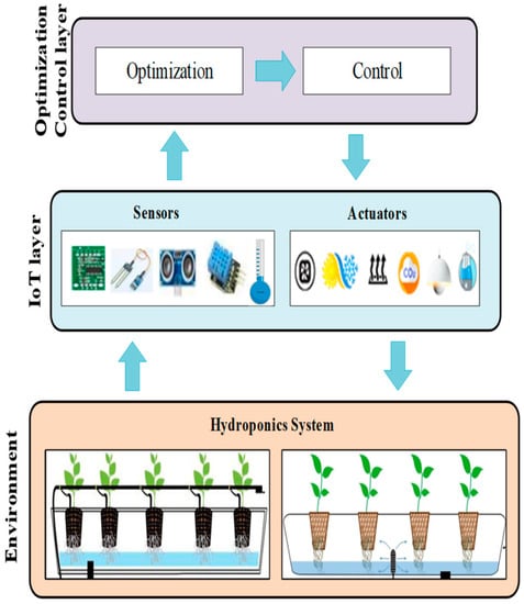
Figure 1.
Hydroponics layered model with the proposed optimization and control scheme.
The detailed conceptual design is described in Figure 2. It can be clearly seen that there are six IoT devices, humidity and water level sensors, and four actuators for controlling these environmental parameters. For the proposed approach an integrated system was developed that included three main modules, namely, data acquisition, optimization and control. The data acquisition unit includes water and humidity levels’ sensing data process through sensors. An objective function, which we suggested to the optimization module, can compute optimum water and humidity level for plant growth according to user/farmer desired settings and system constraints for achieving efficient energy consumption. The fuzzy logic control module was utilized for setting the working level and operational duration limit to the actuators based on IF-THEN rules with considering the current sensing data and optimized data. For instance, if the current water level was less than the optimal water level, then the water pump was activated and increased the water level. If the current water level was higher than the optimal water level, then the overflow system was activated and decreased the water level. If the current water level was equal to the optimal water level, both a water pump and overflow actuators were not activated. Dehumidifier and fogging system actuators were also activated and deactivated based on inference rules, which were described in the next sections.
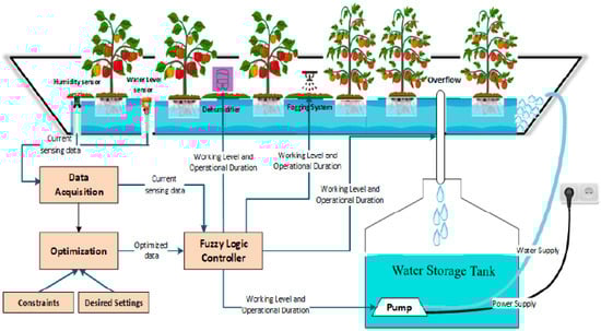
Figure 2.
Hydroponics configuration with proposed optimization and control scheme.
Figure 3 illustrates the flow chart of the proposed IoT based the hydroponics system. As we mentioned above, the whole process includes three main steps. First, we monitored the hydroponics environment by gathering various data (e.g., humidity and water level) through sensors, and this data was collected to the data acquisition unit. Secondly, we applied the optimization scheme to calculate optimal conditions and energy consumption according to user desired settings, power source and system constraints. The power source was the required power (measured in watts) for actuators. Based on the actuator’s activation unit total required energy consumption could be calculated for each actuator (Section 3.1 Equations (7) and (8)). Finally, the fuzzy logic control module was applied for setting the working level and operational duration to the actuators based on optimized data and current actual data.
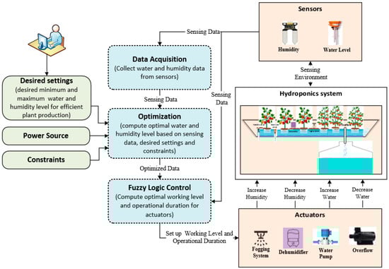
Figure 3.
Hydroponics model flowchart based on proposed optimization and fuzzy logic control scheme.
3.1. Formulation for Optimization
In this section, we described our model for resource optimization in a hydroponics system environment. We developed an optimization model for water supply and humidity, and the same can be extended for other parameters such as temperature, CO2 level and pH. The hydroponics system parameter current parameters are described as for water and environment humidity level. Hydroponics user/farmer can choose the range of acceptable value for this parameter with the desired setting for both parameters as , . Desired settings are the allowed minimum and maximum ranges for each parameter, such that
The maximum and minimum ranges for user desired settings are the most acceptable and the least acceptable settings for hydroponics environment, respectively. If the cost of power is not an issue, the user can set up the maximum parameters for the hydroponics system for improving plant production. Configuring the actuators with maximum working level requires more energy consumption, so a balanced system required between energy consumption and plant production, we also consider the length between the minimum and maximum ranges with and .
Table 1 presents a brief description of the various notations used in this formulation.

Table 1.
Description of notations used in the formulation.
Let us assume that optimal settings that can achieve a tradeoff between desired environmental settings and power consumption is given by
Such that optimal value of each parameter is with user desired range for that parameter, i.e.,
We can assume that the total required energy for maintaining optimal settings for water supply and environment humidity
where and are required energy for optimal settings of hydroponics system water and humidity level, which can be computed as below.
where and are the power consumption by the water pump and overflow in per unit change, respectively. As well as, and describe the per unit change power consumption by the fogging system and dehumidifier actuators. We can assume the possible minimum and maximum power consumption as below
where
We want to have a maximum productive environment is a greenhouse with minimum energy consumption. Let and be the gain in achieving optimal environmental settings and gain in energy saving, respectively. Now, if we express the user-defined preferences for optimal environmental settings and energy-saving with and then our objective function will become.
Such that . The gain in achieving optimal environmental settings can be computed as below.
and describe the deficiency in achieving optimal settings for water level and humidity, respectively. and are the weight assigned to each parameter, depending upon its importance for plant productivity such that In order to maximize the gain in achieving desired the optimal setting , we need to minimize the deficiency component for each parameter, which is given by following the formula.
In order to maximize indoor parameter optimal settings, we need to minimize deficiency component . When then our desired optimal setting would be to set . When then which will help in maximizing the desired . The gain in energy saving can be computed as below, the same case for humidity level too.
In order to maximize energy-saving, we need to minimize the energy consumed in achieving optimal settings i.e., . When then which will help in maximizing the energy-saving component . Thus, our final objective function will become
Constraints:
4. Proposed Fuzzy Logic Control Mechanism
As we already explained above, fuzzy logic control is utilized for setting the working level and operational duration for actuators with analyzing current and optimized data. Providing an optimal environment for the hydroponics system helps to create an optimal production environment for plants. Fuzzification, fuzzy inference engine and defuzzification are essential components of the fuzzy logic system design [33,34]. The fuzzification is a converting process of the real crisp values to the linguistic values. The fuzzy inference engine is the central unit of fuzzy logic systems for decision making based on “IF-THEN” rules along with connectors for providing important decision rules. Defuzzification is the process of converting the linguistic variable to the numerical values. Fuzzy logic describes human preferences and experiences via fuzzy rules and membership functions. Every linguistic variable is associated with confidence values, so each of them has its confidence value. A linguistic variable definition is utilized for describing a membership function graph. Figure 4 illustrates the proposed system fuzzy logic control module part. It can be seen that the data acquisition part contains current water and humidity sensing values of the hydroponics system.
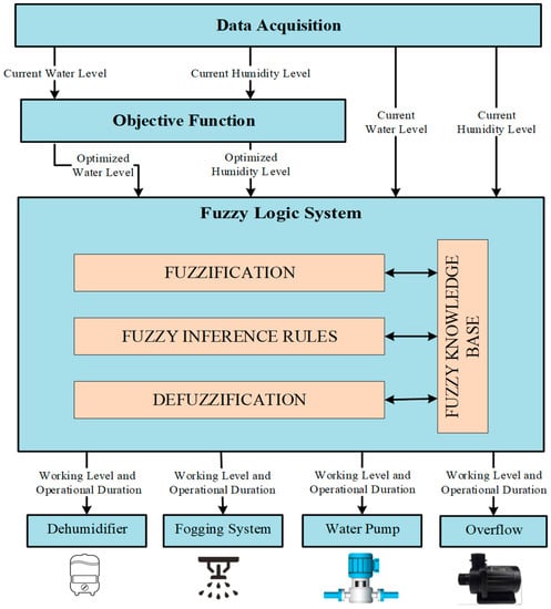
Figure 4.
The general fuzzy logic control module for the proposed optimization based hydroponics model flowchart.
There are four input parameters to the fuzzy system current and optimized levels of the water and humidity sensing data. The fuzzy logic system calculates the most acceptable working level and operational duration to the actuators according to the current and optimized sensing levels.
The fuzzification step takes four input parameters current and optimized water and humidity levels. Input values are labeled as very low, low, medium, high, very high and optimized. The fuzzy inference rule can be used for evaluates input values based on IF-THEN conditional statements; these rules are used for finding out actuators’ working level and duration. To find out the working level and operational duration, the defuzzification phase sets rule with exact working level and minutes to actuators. For instance, if the required duration to the system is Little Time, then fuzzy logic sets 3–6 min of working time to the actuators. In the coming subsections, we will explain detailedly the fuzzification, inference rules, and defuzzification processes according to our proposed approach.
4.1. Fuzzification
Fuzzification is an operation that translates crisp input values to the linguistic variables. As we have already mentioned above, the system takes four input parameters, more precisely, current and optimized levels of water and humidity sensing data values. Acceptable fuzzy linguistic variables are selected for each fuzzy variable.
- Input: current water and humidity level (very low, low, normal, high and very high);
- Input: optimized water and humidity level (optimal);
- Output: actuator working-level (minimum, medium and maximum);
- Output: actuator operational duration (offtime, very little, little, normal, much and very much).
As can be seen from input parameters, we divided the current water and humidity sensing data values into five categories. The other input parameter was optimized water and humidity level; the objective function calculated the optimal level for each parameter per unit. Based on fuzzy rules, the system provided the working level and operational duration for variable level actuators. For the sake comparison, the working level of actuators was taken in three levels, namely, minimum, normal and maximum levels. When variable working-level actuators were activated with the various working level, they spent different time and energy for improving the current environment to the optimal environment.
4.2. Membership Function Graph
4.2.1. Membership Function Graphs for Input Parameters
Graphs of the membership function are described based on the input and output parameter variables. The membership function presents the degree of the truth in fuzzy logic. The values of the ranges for the input and output variables were determined and obtained from our experimental environment. Figure 5 describes the membership function graph for water level fuzzy controller in both current and optimized water level case. Current water and humidity levels are labeled as VL, L, M, H and VH that are abbreviated for very low, low, medium, high and very high. Figure 5a describes that current water level sensing data was between 200 and 350 mm per minute. It could be assumed from the graph that if the current water level was anywhere between 200 and 230 mm, then the fuzzy set was labeled as very low. If the water level was between 305 and 320 mm then the fuzzy was marked as high. These considerations are acceptable to other labels, namely low, medium and very high. As we have already explained in Section 3.1 (Equation (4)) optimized water level was calculated between the minimum and the maximum user-desired set points.
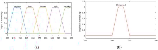
Figure 5.
Membership function graphs for water level (mm). (a) Current waterlevel. (b) Optimized water level.
In our experimental environment, we assumed the most acceptable water level for our system was between 280 and 300 mm. However, users could insert their desired set-points to the system through the main application simulator, it helps to compute new optimal parameters in various conditions. Figure 6 presents membership function graphs for the current humidity level and optimized humidity level based on current sensing data and objective function, respectively.
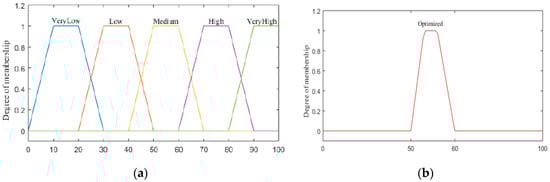
Figure 6.
Membership function graphs for humidity level (%). (a) Current humidity level. (b) Optimized humidity level.
The humidity level linguistic variables were also assumed as very low, low, medium, high and very high. If the percentage of the current humidity is less than 20%, then the fuzzy set is labeled as very low. If the humidity level is between 70% and 80%, then the fuzzy set is labeled as high in Figure 6a. The rest of the labels are also considered as the same case. The optimized humidity level ranges are described in Figure 6b. As we already mentioned above, the objective function computes the optimal value for the hydroponics environment based on user-desired settings and constraints. The optimal humidity level ranges were assumed between 50% and 60%.
4.2.2. Membership Function Graphs for Output Parameters
Our proposed approach presents an optimization scheme for automated hydroponics system with setting up a working level and operational duration to the actuators. As we have described above, output parameters are working level and operational duration for each actuator. Four types of actuators are mentioned in this research, namely, water pump, overflow, fogging system and dehumidifier, however, the proposed scheme can be applied to other types of actuators These actuators activate automatically according to sensing data in per unit. In general, if Hcur < Hopt, then the fogging system is activated and if Hopt < Hcur then the dehumidifier is needed to operate. For hydroponics system water level if Wcur < Wopt then the water pump is operated. If Wopt < Wcur then we need to operate overflow actuator. We have divided the variable speed actuators working level in three categories, namely, minimum level, medium level and maximum level. These working levels are labeled as MinLev, MedLev and MaxLev. It is clear that different working levels and speed operation of actuators required different power consumption. Figure 7 presents the actuators’ power rating ranges according to the three working levels, namely, minimum, medium and maximum. x1, x2, x3 and x4 describe range points of membership function graphs for output parameters. Each actuator has different power consumption according to its operational process.
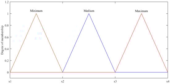
Figure 7.
Actuators’ working-level graph with equivalent power ratings (watts).
Table 2 presents the typical power rating in a minute for hydroponics actuators in three working levels. If the water pump actuator activates with a minimum working level, then it spends power range between 600 (x1) and 1000 (x2) watts per minute. If the water pump is activated with the medium working level, it requires from 1000 (x2) to 1400 (x3) watts. In maximum working level case, the water pump consumes from 1400 (x3) to 1800 (x4) watts for per minute activation. The same applies to all other actuator linguistic variables and power ratings as well.
Table 2.
Power consumption ratings of actuators’ working level.
As we mentioned already, the selection of the exact duration for actuators plays an essential role in both automatizations of the hydroponics system and efficient energy management. If current sensing data is labeled as very low, then actuators have to work with one of the working levels (minimum, medium or maximum). According to actuators’ working level or speed, the operational duration of actuators also becomes different until reaching the optimal environment for the hydroponics system. More precisely, if the water pump operates with a minimum working level, it spends very much time. Conversely, when the water pump works with maximum working level, it requires very little time. Figure 8 illustrates the membership function graph for actuator activation duration. Output variable of the actuator working duration has six membership functions; these membership functions are labeled as OFF, VLT, LT, NT, MT and VMT that are abbreviated for actuator off, very little time, little time, normal time, much time and very much time. The working duration of the actuators is described in minutes and time ranges are determined and obtained from our agricultural and technological knowledge. These membership functions are acceptable for all actuators’ operational duration. If current sensing data is equal to the optimal data, the working duration for actuators becomes zero minutes, and no needed to activate the actuator (OFF). If current sensing data is very low compared to optimized data, the actuator has to be activated very much time (12–15 min) to achieve the desired optimal environment.
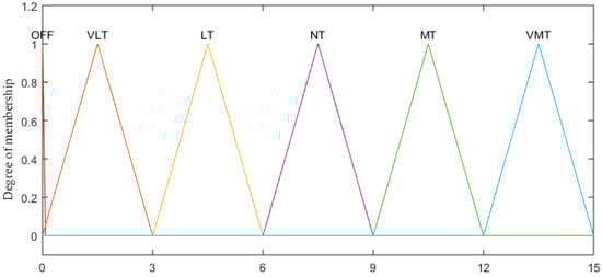
Figure 8.
Membership function graph for actuators’ operational duration (min).
4.3. Fuzzy Inference
A fuzzy knowledge base is a group of knowledge and inference rules for solving specific problems. It is developed to imitate human decision for finding a solution to problems and providing information [35]. Fuzzy inference is the process where the controller analyzes and evaluates input values based on conditional statements. Fuzzy rule evaluation can be performed using the fuzzy associative matrix (FAM) [36]. The FAM table is essential for describing the rule editor into matrix form showing all possible outputs according to all possible inputs. As can be seen from Table 3, from input parameters, current sensing data is labeled into five categories, namely, very low, low, medium, high and very high. As we explained above, optimized data is generated based on a novel objective function. The water pump and overflow system work dependently. When the current water level is less than the optimal water level, then we need to activate the water pump and increase the water level until it reaches the optimal point. Conversely, if the current water level is higher than the optimal water level, the overflow system has to be activated to decrease the current water level until it reaches the optimal point. As a result, when one actuator’s status is ON, the other one is OFF. * sign can be accepted as “with”.
Table 3.
Fuzzy associative matrix for the hydroponics in water level case.
The above mentioned fuzzy associative matrix table applies to the hydroponics system humidity level as well as the fogging system and dehumidifier actuators too. The fuzzy rules are developed according to the FAM by utilizing the IF-THEN statement. The rules define the conditions expected and outcomes. The rule base is a collection of rules to the fuzzy sets, the input variables and the output variable. Table 4 includes fuzzy logic inference rules for hydroponics system water level based on FAM:
Table 4.
Fuzzy logic inference rules for the hydroponics water level.
After analyzing both optimization and fuzzy logic modules, we developed the algorithm for the proposed system values. The below-mentioned Algorithm 1 describes only water level optimization and control mechanism. However, the implemented system also includes an algorithm to the humidity level. The optimal water level control consists of the “optimization scheme” section and the “fuzzy logic control scheme” section as shown in Algorithm 1. As an initial process user has to set the minimum (W_min) and maximum (W_max) user set-points to the system through the application interface. The aim of the optimization scheme section is to calculate the optimal water level (W_opt) to the hydroponics environment based on an objective function, which is described step by step in Section 3.1. The objective function computes the optimal water level based on current sensing data, user-desired settings and system constraints. After that, the current water level and optimized level values send to the fuzzy logic control module, and this module sets the working level and operational duration to the water pump and overflow system actuators based on the IF-THEN concept as described detailedly in Section 4.
| Algorithm 1. Proposed System Algorithm for Optimal Water Control | |
| Initial: Calibrate sensors and actuators | |
| Set User desired settings: Based on Equation (1) | |
| Set System Constraints Based on Equation (14) | |
| Start sensing: | |
| 1: | procedure OPTIMIZATION SCHEME |
| 2: | Comment: Using Objective Function to find out optimal parameters. |
| 3: | Calculate Based on Equation (13) |
| 4: | then |
| 5: | send: |
| 6: | to the |
| 7: | FUZZY LOGIC CONTROL SCHEME (); |
| 8: | end procedure |
| 9: | procedure FUZZY LOGIC CONTROL SCHEME |
| 10: | input 1: |
| 11: | input 2: |
| 12: | if==then |
| 13: | activateActuator(ALL, OFF) |
| 14: | else if == VeryLow and < then |
| 15: | activateActuator(Overflow, OFF) |
| 16: | activateActuator(Waterpump, Values=[MinLevel * VMT, MedLev*MT, MaxLev * NT]) |
| 17: | else if == Low and < then |
| 18: | activateActuator(Overflow, OFF) |
| 19: | activateActuator(Waterpump, Values=[MinLevel * MT, MedLev * NT, MaxLev * LT]) |
| 20: | else if == Medium and < then |
| 21: | activateActuator(Overflow, OFF) |
| 22: | activateActuator(Waterpump, Values=[MinLevel * NT, MedLev * LT, MaxLev * VLT]) |
| 23: | if == Medium and > then |
| 24: | activateActuator(Waterpump, OFF) |
| 25: | activateActuator(Overflow, Values=[MinLevel * NT, MedLev * LT, MaxLev * VLT]) |
| 26: | else activateActuator(ALL, OFF) |
| 27: | else if == High and < then |
| 28: | activateActuator(Waterpump, OFF) |
| 29: | activateActuator(Overflow, Values=[MinLevel * MT, MedLev * NT, MaxLev * LT]) |
| 30: | else if == VeryHigh and < then |
| 31: | activateActuator(Waterpump, OFF) |
| 32: | activateActuator(Overflow, Values=[MinLevel * VMT, MedLev * MT, MaxLev * NT]) |
| 33: | end if |
| 34: | end procedure |
5. Hydroponics Experimental Environment
This section presents an overview of the implementation tools and experimental hydroponics environment for the proposed system. The experiment was conducted in Mobile Computing Laboratory; the room number was D423 at Jeju National University during the period May 2019 to July 2019. Figure 9 shows the hydroponics system data acquisition process from the real environment, which we developed as a case study. Arduino acts as the IoT gateway, which serves as the connection unit among sensors, actuators and the server. Arduino [37] is an open-source lightweight electronic platform that can provide hardware and software services [1]. In our proposed system, Open Aquarium Shield is installed for connecting all of the sensors and actuators to the IoT gateway, ESP8266 Wi-Fi Module is attached to the IoT gateway for the providing access to Wi-Fi network.
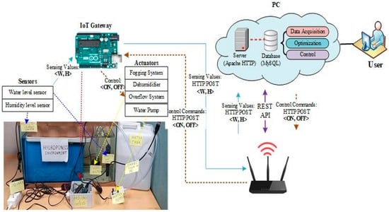
Figure 9.
Data acquisition process.
Sensing values are sent to the Apache HTTP server with an HTTP POST request and these values are stored to the MySQL database. W and H describe water level and humidity level sensing values respectively. Afterward, the user can be able to use the stored data for the optimization and control modules. Fuzzy logic control module activates (ON) or deactivates (OFF) actuators with computed working level and operational duration. Figure 10 depicts the hydroponics system main application interface.
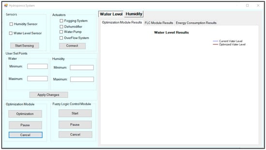
Figure 10.
The hydroponics simulator interface.
Three types of results can be seen in the proposed system simulator interface, namely, optimization module, FLC module, and energy consumption result. It can be seen that the interface of the system includes sensors, actuators, user-set points, optimization and fuzzy logic control modules, as well as, the results of the system can be easily visible from the water level and humidity sub-windows. Table 5 shows the technologies used on a general-purpose machine for the implementation environment.
Table 5.
Specification of implementation environment of general-purpose PC.
For the evaluation of the effectiveness of the proposed approach, a real hydroponics environment was designed as a part of the experimental work. Figure 11 describes the experimental environment of the hydroponics system. As can be seen from the experimental hydroponics environment, the water and humidity level sensor, water storage tank, the overflow system actuator and water pump actuators were installed to the hydroponics environment successfully and the proposed system was providing optimal water level automatically to the hydroponics environment. Due to the limited technological resources, the fogging system and dehumidifier actuators were not installed. However, the results part also included humidity results based on applying humidity level data. Table 6 indicates utilized IoT devices for the development of an experimental hydroponics environment.
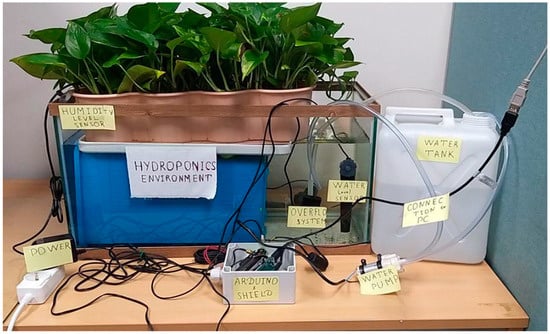
Figure 11.
Hydroponics experimental environment.
Table 6.
Description of IoT devices for the experimental hydroponics environment.
Table 6 includes IoT devices, which can be considered for the conduction of these experiments.
6. Experimental Results of Proposed System
Next, we present a detailed discussion of our performance evaluation results. For a clear explanation, we described our results in four phases. Phase 1 describes the optimization results of the system based on a novel objective function. Phase 2 is about the fuzzy logic control module results. Thirdly, we presented energy consumption results according to the actuators working levels. Lastly, we compared energy consumption results based on optimization and without optimization schemes, in order to evaluate the advantages of the optimization module.
6.1. Analysis of Optimization Module Results
Once the user runs the hydroponics system’s main application, the system obtains sensor reading data from the attached hydroponics system. The user can be able to view the results as the simulation proceeds, which include optimization results and actuators operations results on different tab pages. As we mentioned above, we monitored the hydroponics environment by gathering water and humidity level data through a water and humidity level sensor. After that, gathered data to the local database was applied to the optimization and FLC modules; the optimization module calculated optimal water and humidity level with optimal resource utilization. The FLC module set the rule to the actuators for controlling working level and duration for achieving an optimal condition to the hydroponics system. Figure 12 and Figure 13 show optimization module results for the water and humidity level, respectively. The graphs included the ranges between user-set points and current sensing data for analyzing optimization results. As can be seen from the chart, the current water level line indicates the actual sensing data of the hydroponics system water level. The actual water level was between 200 and 349 mm in the first 120 instances of sensing data. For our experiment, we chose the user desired settings for the minimum and maximum ranges as 280 mm and 300 mm, respectively. However, the user could change the desired set points from the main interface of the application according to the requirements of his or her hydroponics system. The optimized water level line shows the optimization results of the system.
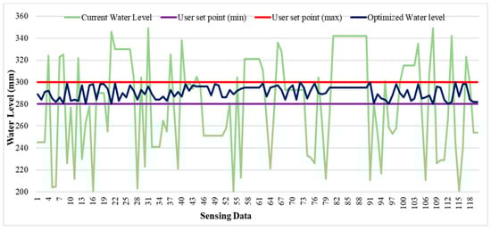
Figure 12.
Optimization scheme results for the water level.
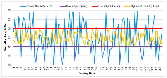
Figure 13.
Optimization scheme results for the humidity level.
The current humidity level indicates the actual data of the proposed system level before optimization. The actual humidity level was between around 40% and 70%. The minimum and maximum setpoints were equal to 50% and 60% respectively, which means these ranges were acceptable for providing optimal condition to the hydroponics system. The objective function automatically calculated the optimized level according to each sensing humidity data. If electricity power and resources are not limited, the user always can catch the maximum set point to boost plant production. The optimized humidity level always came inside of the min and the max user-desired settings, which means the objective function was working accurately.
6.2. Analysis of Fuzzy Logic Control Module Results
Generally, fixed and variable working-level water pumps, the fogging system and dehumidifiers are utilized in agriculture. The fixed working-level actuators operate with a specific speed and consume the same amount of energy for each task. On the other hand, the variable speed or working level devices can operate with various working levels to produce different water or humidity level according to the user demand. It is clear that a high working level requires more energy as compared to the lower working levels. In the hydroponics or the greenhouse environment, the power consumption of the actuators can be minimized by decreasing the working level, but it requires to operate actuators with extra time. For example, if the water pump needs to be activated with the flow rate of 40 for 4 h in a day, then operating the same water pump with 20 will require 8 h of operation in a day. Figure 14 illustrates the water pump and overflow system working level and operational duration results in the first 120 sensing data. The water pump and overflow system work dependently. If the current water level is lower than the optimal water level, then the water pump is activated for reaching the optimal water level. If the current water level is higher than the optimal water level, the overflow system operates for decreasing the actual water level to the optimal level. As you can see from the graphs when actuators were working with a different level, they required different time for achieving the optimal point. For instance, in the first sensing data, the water pump was spending 4.5, 7.5 and 10.5 min with the minimum, medium and maximum working levels, respectively.
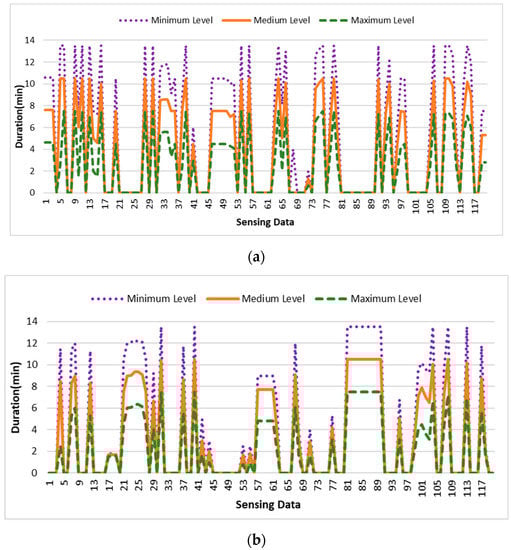
Figure 14.
Operational duration results based on different working levels. (a) Water pump. (b) Overflow system.
Figure 15a,b describes the working level and duration results of the humidity level of the hydroponics system. For instance, for the 3–4 sensing data, the fogging system was spending about 1.8, 4.2 and 7.6 min with the minimum, medium and maximum working level, respectively. However, in these points, the dehumidifier actuator status was off. We made a group of the results according to the actuators working level. However, the proposed fuzzy logic control module selected the optimal working level and duration to the actuators according to the actual and optimal data. Controlling actuators not only helps the optimal utilization of resources but also provides automation of the hydroponics system.
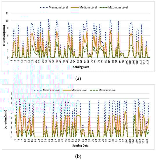
Figure 15.
Operational duration results based on different working levels. (a) Fogging system. (b) Dehumidifier.
Based on the working-level level and operational duration, we could calculate the overall operational duration for each actuator; computing the activation period of the actuators based on different working-level helped us to calculate energy consumption for each level. Figure 16 shows the total operational duration of the actuators in minutes according to the different working levels.
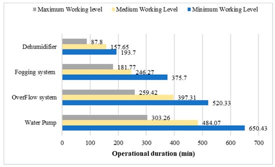
Figure 16.
Actuators’ operational duration results based on different working levels.
6.3. Analysis of Energy Consumption Results
To calculate energy consumption analysis, we selected power ratings as in Table 2. For every actuator, we assumed three working-level operations with different energy consumption. For module simplicity, we took the mid-point of the power rating ranges of the working levels. For instance, with the minimum, medium and maximum working level, the water pump required 800, 1200 and 1600 watts, respectively. The same applied to all other actuators with different working levels, as described in Figure 7. Figure 17 illustrates the actuators’ energy consumption results in kWh according to the different working levels. As can be seen from the graphs, power consumption by the water pump was dominating comparing with other actuators. The water pump was spending 520, 581 and 485 kWh with activating minimum, medium and the maximum level, respectively. If the water pump is activated with maximum working level, then it consumes less energy, and when it works with the medium working level, it spends the most power compared to other working levels. For achieving optimal humidity level according to 120 instances of sensing data, the fogging system and dehumidifier have to be activated with a maximum working level for efficient energy consumption.
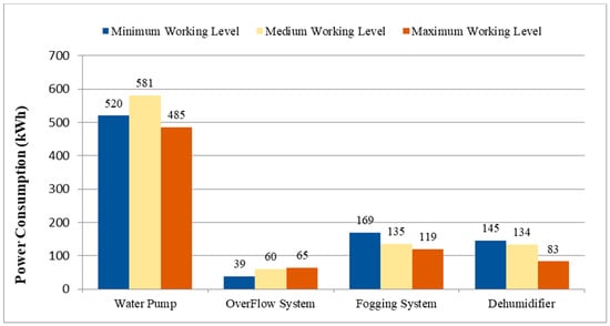
Figure 17.
Comparative analysis of the actuators’ energy consumption results.
Overall, activating the water pump, fogging system and dehumidifier actuators with maximum working levels helped to reduce energy consumption. However, the overflow system was needed to activate with a minimum working level in order to achieve lower power consumption.
6.4. Comparisons of Energy Consumption Results Based on Optimization and without Optimization
For the sake of validation of the energy usage of the proposed optimization scheme, we ran our system without the optimization module by setting up the maximum working level to the actuators. As we mentioned above, the optimization module provided optimal water and humidity levels to the environment based on user-desired settings and constraints. According to the optimal level, the current values of the environment could be increased with controlling actuators. For the development of without optimization scheme, we used the baseline scheme, which is relatively simple. The baseline scheme was based on the selection of the midpoint of user-desired ranges for each parameter. For instance, if the user desired maximum and minimum ranges humidity level ranges were equal to 50% and 60%, respectively. Optimal humidity level became equal to 55% ((50% + 60%)/2 = 55%). The dehumidifier or the fogging system was needed to activate for increasing or decreasing the current humidity level for achieving the optimal point. From the above-mentioned user-desired mid-point level selection, humidity and water level optimal levels become 55% and 290 mm, respectively. Our target was controlling the actuators for reaching the current levels for these levels. The same working level, operational durations and fuzzy logic rules were also applied to the without optimization module. Figure 18 depicts the analysis of actuators’ overall energy usage results for the 120 sensing values based on optimization and without optimization schemes with considering maximum working level for all actuators. Energy consumption results show that through an optimization scheme. The overall energy consumption was higher in without the optimization case as expected, i.e., 915 kWh, whereas optimization scheme based energy consumption was low, i.e., 752 kWh. Through the optimization scheme, we were able to decrease energy consumption significantly (18%).
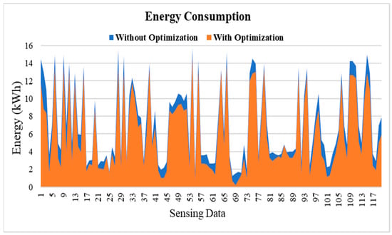
Figure 18.
Comparison of energy consumption results.
7. Comparison and Significance
In this section, we provided a brief description of the significance of this work by comparing it with existing scenarios that have already been suggested for hydroponics environment control. As we already described in previous sections of the paper, this work is a novel attempt to support optimization for both environmental parameters and energy consumption. In order to assess the efficiency of the proposed work, related hydroponics control systems were discussed in the Related Works Section. Table 7 summarizes comparisons between the proposed system and existing researches. The table shows that the proposed approach outperformed the related works in some aspects. Many existing applications proposed IoT based control for hydroponics based on current environmental parameters. When the current sensing value reached the threshold farmer receives notifications, then the farmer switches off or on the actuators remotely. The proposed system has more advanced functionalities; first, an objective function, which has been developed for optimization, can support the optimum level for environmental parameters. Second, the fuzzy logic control module automatically sets the working level and operational duration to the actuators; in the required time, actuators turn on or off without human inference. Lastly, optimization-based energy consumption calculations help to reduce the cost of expenses. The proposed model can be applied to other potential problems such as greenhouse indoor parameters optimization, fish farm environment control and so on. The proposed optimization and control schemes are flexible and scalable when more environmental values and devices are added. However, the system faces some limitations in terms of flexibility. As the number of devices and sensing parameters is increased dramatically, the calculation duration of the optimal parameters also increases and its influence on the operational process as well.
Table 7.
Comparative analysis of the proposed system with existing applications.
8. Conclusions
Automatization of agricultural fields with optimal resource utilization is a challenging task because of different external and internal factors. To maintain better management in both resources and energy, we proposed the automated water and humidity level control system with efficient energy consumption for hydroponics environment based on optimization and fuzzy logic control. A novel objective function can provide optimal water and humidity level based on user-desired settings and system constraints. The fuzzy logic control module was utilized for finding optimal working level and operational duration to the actuators with analyzing the current and optimized data of the water and humidity levels in the experimental environment. By controlling the actuators’ working level and operational duration, we achieved the optimal water and humidity supplement system to the hydroponics environment with efficient energy consumption. In our experimental environment, we used water level and humidity level sensors for checking the current condition of the hydroponics environment. Four actuators, namely, water pump, overflow, the fogging system and dehumidifier were mentioned in this paper; however, the water pump and the overflow system actuators have been deployed to provide optimal condition to the experimental environment. Through analyzing simulation results, we observed that the objective function-based optimization scheme achieved an 18% energy reduction in the 120 instances of sensing data as compared to the baseline scheme. Future work will be devoted to achieving less energy consumption, as well as expanding the optimization model to more complex contexts, such as greenhouse environment control and fish farm control, just to name a few.
Author Contributions
A.K. conceived the idea of the paper, designed the experiments and wrote the paper; S.A. and I.U. assisted in model designing and experiments. D.K. conceived the overall idea of the proposed hydroponics system and proof-read the manuscript. All authors have read and agreed to the published version of the manuscript.
Acknowledgments
This research was supported by Energy Cloud R&D Program through the National Research Foundation of Korea (NRF) funded by the Ministry of Science, ICT (2019M3F2A1073387), and this research was supported by Basic Science Research Program through the National Research Foundation of Korea (NRF) funded by the Ministry of Education, Science and Technology (2018R1D1A1A09082919). Any correspondence related to this paper should be addressed to DoHyeun Kim.
Conflicts of Interest
The authors declare no conflict of interest.
References
- The World Population Prospects: 2015 Revision; U.N. Department of Economic and Social Affairs: New York, NY, USA, 2014. Available online: http://www.un.org/en/development/desa/news/population/2015report.html (accessed on 10 May 2019).
- Oki, T. Encyclopedia of Hydrological Sciences; Anderson, M.G., McDonnell, J., Eds.; Wiley: New York, NY, USA, 2005; Volume 1, pp. 13–22. [Google Scholar]
- The Future of Food and Agriculture: Alternative Pathways to 2050; Food and Agriculture Organization of the United Nations: Rome, Italy, 2018. Available online: http://www.fao.org/statistics/en/ (accessed on 19 May 2019).
- Tripathi, P.; Rabara, R.C.; Shulaev, V.; Shen, Q.J.; Rushton, P.J. Understanding water-stress responses in soybean using hydroponics system—A systems biology perspective. Front. Plant Sci. 2015, 6, 1145. [Google Scholar] [CrossRef] [PubMed]
- Chapae, C.; Songsri, P.; Jongrungklang, N. Hydroponics: An Alternative Method for Root and Shoot Classification on Sugarcane Genotypes. AGRIVITA. J. Agric. Sci. 2019, 41, 351–363. [Google Scholar] [CrossRef]
- Gilmour, D.N.; Nayga, R.M.; Bazzani, C.; Price, H. Consumers’ Willingness to Pay for Hydroponic Lettuce: A Non-hypothetical Choice Experiment; No. 2015-2018-232; University of Arkansas: Fayetteville, NC, USA, 2018. [Google Scholar]
- Sharma, N.; Acharya, S.; Kumar, K.; Singh, N.; Chaurasia, O.P. Hydroponics as an advanced technique for vegetable production: An overview. J. Soil. Water Conserv. 2018, 17, 364–371. [Google Scholar] [CrossRef]
- Bouchard, D.M. Hydroponic Systems. Hortic. Eng. 2005, 13, 1–10. [Google Scholar]
- Khudoyberdiev, A.; Jin, W.; Kim, D. A Novel Approach towards Resource Auto-Registration and Discovery of Embedded Systems Based on DNS. Electronics 2019, 8, 442. [Google Scholar] [CrossRef]
- Gubbi, J.; Buyya, R.; Marusic, S.; Palaniswami, M. Internet of Things (IoT): A vision, architectural elements, and future directions. Future Gener. Comput. Syst. 2013, 29, 1645–1660. [Google Scholar] [CrossRef]
- Mehmood, F.; Ullah, I.; Ahmad, S.; Kim, D. Object detection mechanism based on deep learning algorithm using embedded IoT devices for smart home appliances control in CoT. J. Ambient Intell. Humanize Comput. 2019, 1–17. [Google Scholar] [CrossRef]
- Selin, R. The Outlook for Energy: A View to 2040; CEDA–the Committee for Economic Development of Australia: Melbourne, Australia, 2013. [Google Scholar]
- Sieminski, A. International Energy Outlook; Energy Information Administration: Washington, DC, USA, 2014; p. 18. [Google Scholar]
- Jensen, M.H. Hydroponics Worldwide. Acta Hortic. 1999, 481, 719–730. [Google Scholar] [CrossRef]
- What is Apache? An in-depth overview of Apache Web Server. Available online: https://www.hostinger.com/tutorials/what-is-apache (accessed on 12 June 2019).
- Jin, W.; Kim, D. Consistent Registration and Discovery Scheme for Devices and Web Service Providers Based on RAML Using Embedded RD in OCF IoT Network. Sustainability 2018, 10, 4706. [Google Scholar] [CrossRef]
- Greenspan, J.; Bulger, B. MySQL/PHP Database Applications; John Wiley Sons, Inc.: New York, NY, USA, 2001. [Google Scholar]
- Venter, G. Different types of hydroponic systems: Farming for tomorrow. Farmer’s Wkly. 2017, 2017, 26–27. [Google Scholar]
- Hasan, M.; Sabir, N.; Singh, A.K.; Singh, M.C.; Patel, N.; Khanna, M.; Pragnya, P. Hydroponics Technology for Horticultural Crops. Tech. Bull. TB-ICN 2018, 188, 30. [Google Scholar]
- Carskadon, M.; Barrett, P. Patent and Trademark Office. U.S. Patent No. 9,901,044, 27 February 2018. [Google Scholar]
- Lakhiar, I.A.; Jianmin, G.; Syed, T.N.; Chandio, F.A.; Buttar, N.A.; Qureshi, W.A. Monitoring and Control Systems in Agriculture Using Intelligent Sensor Techniques: A Review of the Aeroponic System. J. Sens. 2018, 2018, 8672769. [Google Scholar] [CrossRef]
- Lefers, R.M.; Bettahalli, N.S.; Fedoroff, N.V.; Ghaffour, N.; Davies, P.A.; Nunes, S.P.; Leiknes, T. Hollow fiber membrane-based liquid desiccant humidity control for controlled environment agriculture. Biosyst. Eng. 2019, 183, 47–57. [Google Scholar] [CrossRef]
- Mehra, M.; Saxena, S.; Sankaranarayanan, S.; Tom, R.J.; Veeramanikandan, M. IoT based hydroponics system using Deep Neural Networks. Comput. Electron. Agric. 2018, 155, 473–486. [Google Scholar] [CrossRef]
- Ludwig, F.; Fernandes, D.M. Electrical conductivity and pH of the substrate solution gerbera cultivars under fertigation. Hortic. Bras. 2013, 31, 356–360. [Google Scholar] [CrossRef]
- Peuchpanngarm, C.; Srinitiworawong, P.; Samerjai, W.; Untenanted, T. DIY sensor-based automatic control mobile application for hydroponics. In Proceedings of the 2016 5th ICT Int. Student Proj. Conf. ICT-ISPC, Nakhon Pathom, Thailand, 27–28 May 2016; pp. 57–60. [Google Scholar]
- Ferentinos, K.P.; Albright, L.D. Predictive neural network modeling of Ph and electrical conductivity in deep-trough hydroponics. Trans. ASAE 2007, 45, 2007–2015. [Google Scholar]
- Gosavi, J.V. Water monitoring system for hydroponics agriculture. Int. J. Res. Appl. Sci. Eng. Technol. 2017, 5, 19–34. [Google Scholar]
- Liptak, B.G. Instrument Engineers’ Handbook, Volume Two: Process Control and Optimization; CRC Press: Boca Raton, FL, USA, 2018. [Google Scholar]
- Nesterov, Y. Lectures on Convex Optimization; Springer: Berlin/Heidelberg, Germany, 2018; Volume 137. [Google Scholar]
- Arora, R.K. Optimization: Algorithms and Applications; Chapman and Hall/CRC: Boca Raton, FL, USA, 2015. [Google Scholar]
- Mehmood, F.; Ahmad, S.; Kim, D. Design and Development of a Real-Time Optimal Route Recommendation System Using Big Data for Tourists in Jeju Island. Electronics 2019, 8, 506. [Google Scholar] [CrossRef]
- Zadeh, L.A. Fuzzy logic—A personal perspective. Fuzzy Sets Syst. 2015, 281, 4–20. [Google Scholar] [CrossRef]
- Zimmermann, H.J. Fuzzy Set Theory. WIREs Comp Stats 2010, 2, 317–332. [Google Scholar] [CrossRef]
- Bai, Y.; Wang, D. Fundamentals of fuzzy logic control—Fuzzy sets, fuzzy rules, and defuzzification. In Advanced Fuzzy Logic Technologies in Industrial Applications 2006; Springer: London, UK, 2006; pp. 17–36. [Google Scholar]
- Mohammed, A.A.; Ambak, K.; Mosa, A.M.; Syamsunur, D. Expert System in Engineering Transportation: A Review. J. Eng. Sci. Technol. 2019, 14, 229–252. [Google Scholar]
- Baldovino, R.G.; Dadios, E.P. Fuzzy logic control: Design of a ‘mini’ fuzzy associative matrix (FAM) table algorithm in motor speed control. In Proceedings of the TENCON 2015-2015 IEEE Region 10 Conference, Macao, China, 1–4 November 2015; pp. 1–4. [Google Scholar]
- The official website of the Arduino, “What is Arduino?”. Available online: https://www.arduino.cc/en/guide/introduction (accessed on 19 June 2019).
- Pitakphongmetha, J.; Boonnam, N.; Wongkoon, S.; Horanont, T.; Somkiadcharoen, D.; Prapakornpilai, J. Internet of things for planting in smart farm hydroponics style. In Proceedings of the 2016 International Computer Science and Engineering Conference (ICSEC), Chiang Mai, Thailand, 14–17 December 2016; pp. 1–5. [Google Scholar]
- Tembe, S.; Khan, S.; Acharekar, R. IoT based automated hydroponics system. Int. J. Sci. Eng. Res. 2018, 9, 67–71. [Google Scholar]
- Alipio, M.I.; Cruz, A.E.M.D.; Doria, J.D.A.; Fruto, R.M.S. A smart hydroponics farming system using exact inference in bayesian network. In Proceedings of the 2017 IEEE 6th Global Conference on Consumer Electronics (GCCE), Nagoya, Japan, 24–27 October 2017; pp. 1–5. [Google Scholar]
- Crisnapati, P.N.; Wardana, I.N.K.; Aryanto, I.K.A.A.; Hermawan, A. Hommons: Hydroponic management and monitoring system for an IOT based NFT farm using web technology. In Proceedings of the 2017 5th International Conference on Cyber and IT Service Management (CITSM), Bali, Indonesia, 8–10 August 2017; pp. 1–6. [Google Scholar]
- Saraswathi, D.; Manibharathy, P.; Gokulnath, R.; Sureshkumar, E.; Karthikeyan, K. Automation of hydroponics green house farming using IoT. In Proceedings of the 2018 IEEE International Conference on System, Computation, Automation and Networking (ICSCA), Pondicherry, India, 6–7 July 2018; pp. 1–4. [Google Scholar]
- Changmai, T.; Gertphol, S.; Chulak, P. Smart Hydroponic Lettuce Farm using Internet of Things. In Proceedings of the 2018 10th International Conference on Knowledge and Smart Technology (KST), Chiang Mai, Thailand, 31 January–3 February 2018; pp. 231–236. [Google Scholar]
- Ruengittinun, S.; Phongsamsuan, S.; Sureeratanakorn, P. Applied internet of thing for smart hydroponic farming ecosystem (HFE). In Proceedings of the 2017 10th International Conference on Ubi-media Computing and Workshops (Ubi-Media), Pattaya, Thailand, 1–4 August 2017; pp. 1–4. [Google Scholar]


© 2020 by the authors. Licensee MDPI, Basel, Switzerland. This article is an open access article distributed under the terms and conditions of the Creative Commons Attribution (CC BY) license (http://creativecommons.org/licenses/by/4.0/).