NSGA-II-Based Codesign Optimization for Power Conversion and Controller Stages of Interleaved Boost Converters in Electric Vehicle Drivetrains


 ,
,  , and
, and 
Abstract

1. Introduction
- (1)
- A simultaneous COF based on metaheuristic-evolutionary searching and automatic decision-making algorithms is introduced for high-power multiphase DC/DC converters in EV applications;
- (2)
- Four key objective functions involving both the power conversion stage and the controller stage are well-defined in analytical forms to facilitate the optimization process. The optimal results obtained from the COF using those analytical models are verified by finite element analysis (FEA) simulation and experimental results;
- (3)
- Based on the optimal parameters, a liquid-cooled SiC-based converter and its real-time controller are prototyped and demonstrated. Experimental validations are conducted including (i) a mechanical design for inductor; (ii) integration of the entire converter system in comparison with other prototypes available in the literature; (iii) implementation of field-programmable gate array (FPGA)-based digital controllers; and (iv) static and dynamic load transient testing.
- (4)
- The proposed COF provides a practical design tool to explore holistically the design space of the PE converter. As the proposed COF is considered as a modular approach, it can be simplified or extended considering other aspects such as reliability and total cost of ownership, which may open new research trends.
2. Technology Selections of Power Conversion and Controller Stages
2.1. Technology Selections of Power Conversion Stage
2.2. Controller Type and Control Strategy Selections of Controller Stage
3. Proposed Simultaneous Codesign Optimization Framework
3.1. Principle and Flow Chart of Simultaneous Codesign Optimization
3.2. Objective Functions
3.2.1. Objective Function 1: Total Input Current Ripple
3.2.2. Objective Function 2: Total Inductor Weights
3.2.3. Objective Function 3: Total Converter Losses
Semiconductor Losses
- (i)
- Dead-times loss is neglected,
- (ii)
- The output capacitor loss owning to its equivalent series resistance (ESR) is neglected,
- (iii)
- Junction temperatures are in time constant at 150 °C for the sake of conservative calculation, and the converter operates at the nominal rating power,
- (iv)
- Gate driver loss are neglected because they are considered only for low-power, low-voltage MOSFET applications with very high frequency,
- (v)
- Loss owning to discharging parasitic output capacitor, forward-blocking losses can be neglected in the high-power applications since they only account for a small share of the total power dissipation [40]. In case of high blocking voltages (>1000 V) and/or high operating temperatures (>150 °C), blocking losses may gain importance and may even result in thermal runaway owing to the exponentially rising reverse currents.
Inductor Losses
3.2.4. Objective Function 4: Integral of Time-weighted Absolute Error for Output Voltage Control
3.3. Principle of Simultaneous Codesign Optimization
3.4. Optimal Solution
4. Inductor Design
5. Prototype Demonstration and Experimental Results
5.1. Proposed Hardware Prototype and Comparison
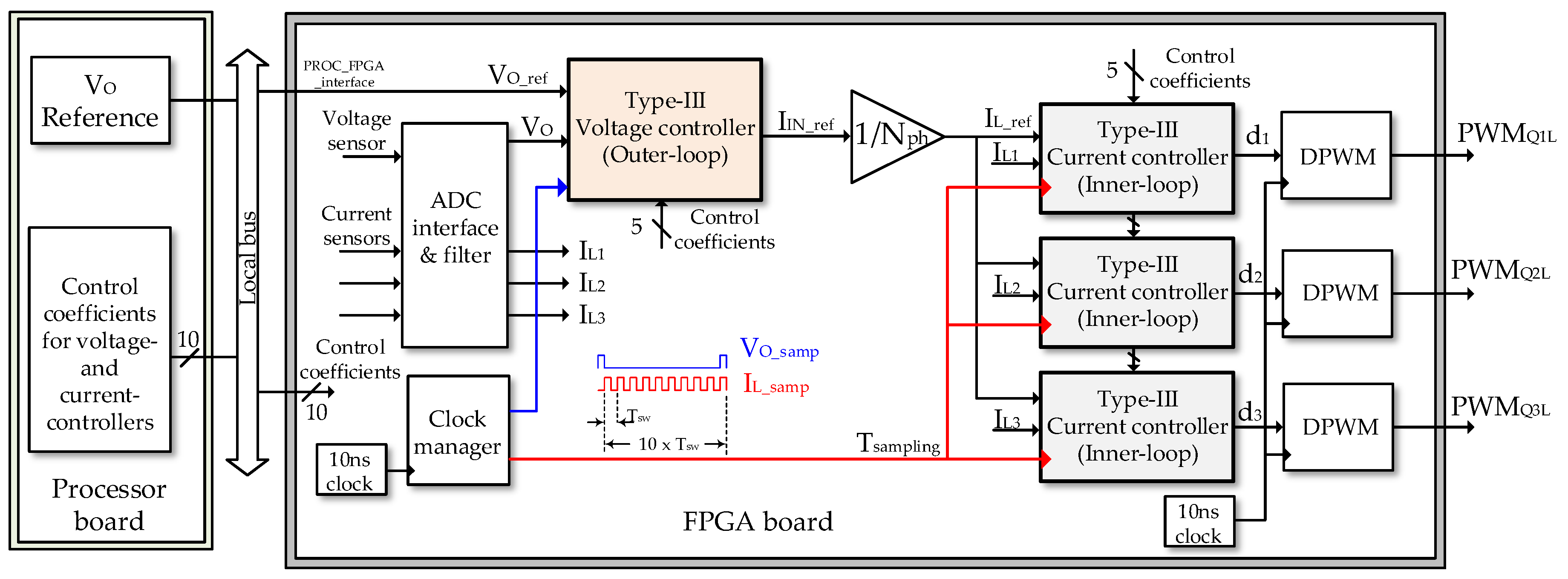
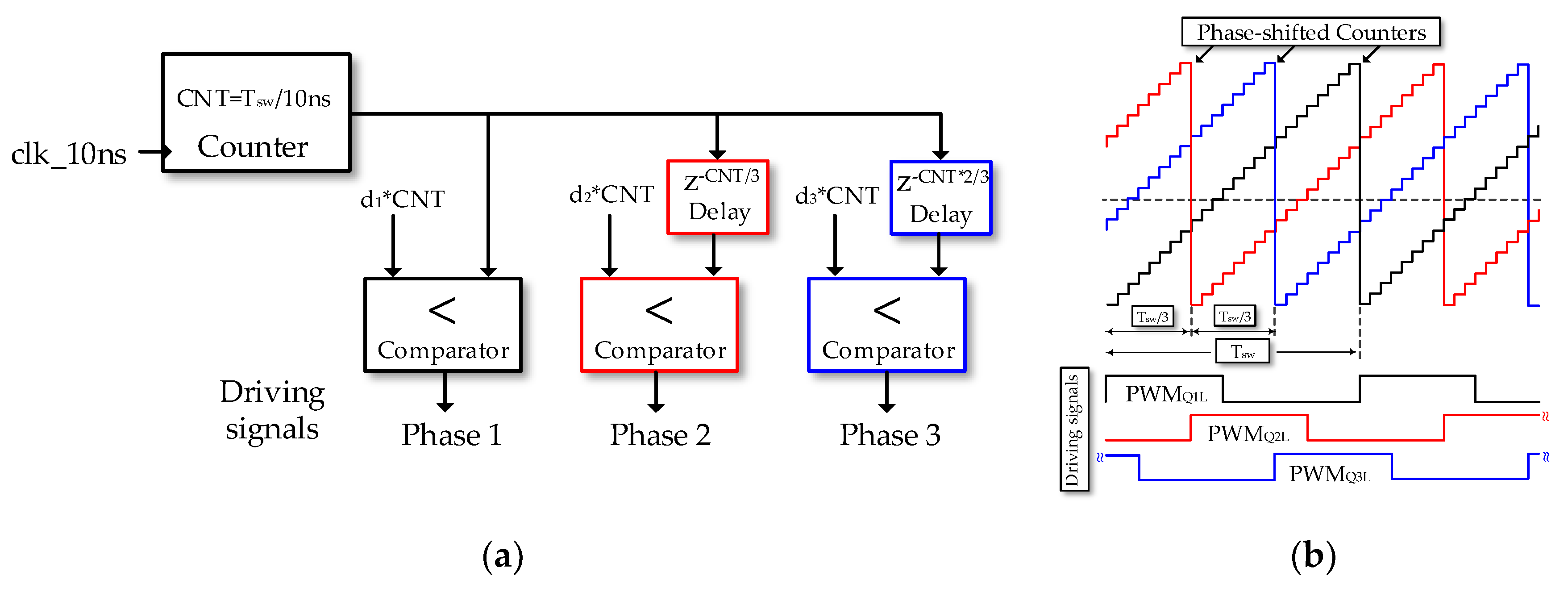
5.2. FPGA Digital Control Implementation
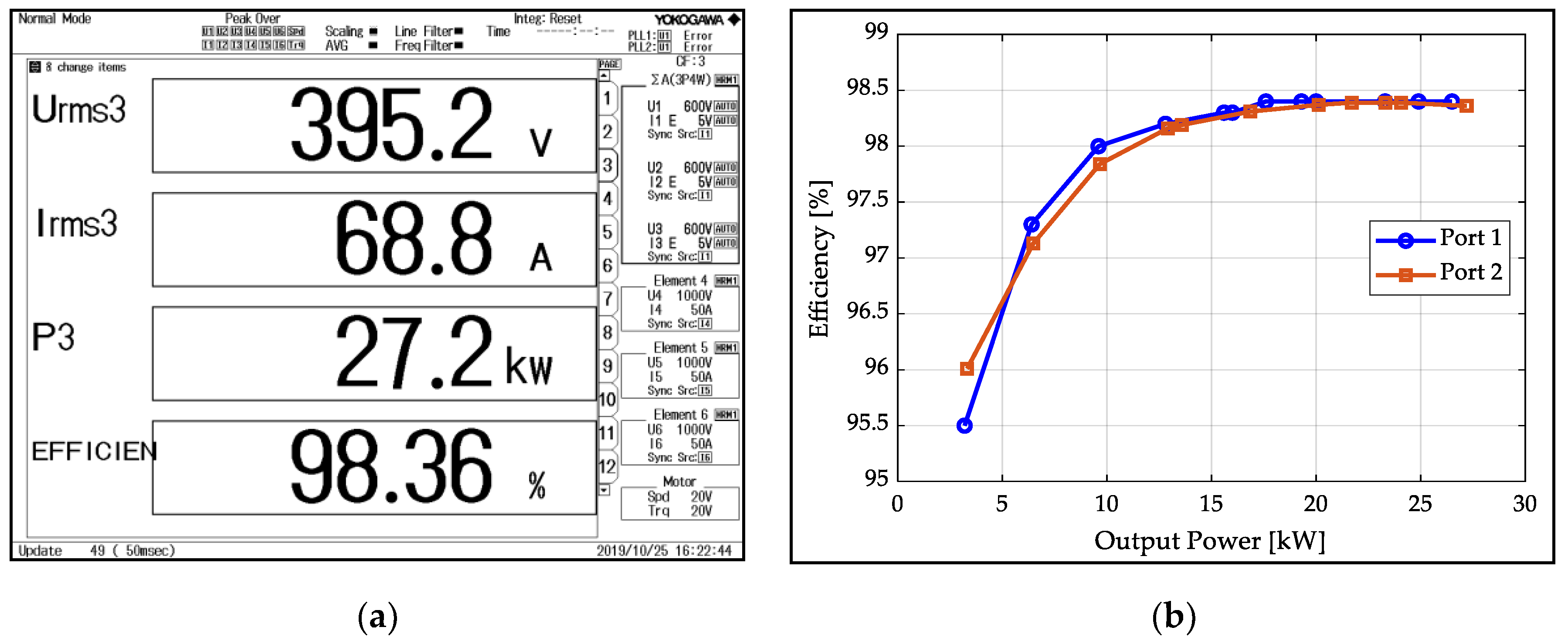
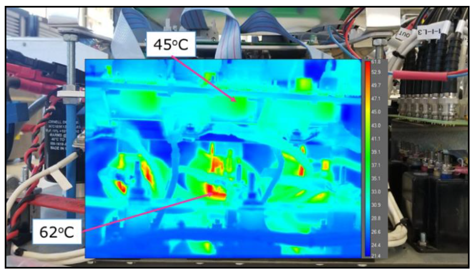
5.3. Experimental Results
6. Conclusions
Author Contributions
Funding
Acknowledgments
Conflicts of Interest
Appendix A

| Parameter | 1200 V CREE CAS300H12BM2 62 × 106 × 30 [mm] | 1200 V CREE CAS325M12HM2 65 × 110 × 10 [mm] | 1200 V SEMIKRON SKM350MB120SCH17 62 × 106 × 30 [mm] | 1200 V ROHM BSM300D12P2E001 62 × 152 × 17 [mm] | 1200 V FUJI Elec 2CSI300CAS120 A-50 42 × 126 × 19 [mm] | |||||
|---|---|---|---|---|---|---|---|---|---|---|
| 0 | 0.825 | 0 | 0.833 | 0 | 1.05 | 0 | 0.705 | 0 | 0.72 | |
| 7.7 | 6.7 | 7.6 | 8 | 9.5 | 12 | 15 | 5.67 | 10.6 | 9.067 | |
| (600 V 300 A) | 5.8 | - | 5.6 | - | 8.65 | - | 9.5 | - | 4.3 | - |
| (600V 300 A) | 6.1 | - | 3.7 | - | 7.98 | - | 10.5 | - | 10 | - |
| - | 0.64 | - | 0.86 | - | 0.088 | - | 0.7 | - | 2.57 | |
| 300 | 325 | 523 | 600 | 600 | ||||||
| 150 | 175 | 175 | 175 | 175 | ||||||
| 0.075 | 0.076 | 0.115 | 0.127 | 0.045 | 0.18 | 0.08 | 0.11 | 0.098 | 0.098 | |
| Weight [g] | 300 | 140 | 325 | 350 | - | |||||
| Cost [€] | 558 | 1306 | 473 | 668 | - | |||||
| Material Name | Manufacturer | Name | Saturation Flux Density (T) | Mass Density (g/cm3) | Initial Relative Permeability | Core Loss @0.1 T, 20 kHz (kW/m3) |
|---|---|---|---|---|---|---|
| Ferrite | Ferroxcube | 3C93 | 0.5 | 4.8 | 1800 | 5 |
| Iron-powder | Manetics | MPP60 | 0.75 | 8.2 | 60 | 45 |
| Nanocrystalline | VAC | Vireoperm500F | 1.2 | 7.3 | 15500 | 5 |
| Amorphous | Metglas | 2605SA1 | 1.56 | 7.18 | 1200 | 70 |
| Silicon-steel | JFE | 10JNHF600 | 1.87 | 7.53 | 800 | 150 |
Appendix B

Appendix C
References
- Hegazy, O.; Barrero, R.; Van Mierlo, J.; Lataire, P.; Omar, N.; Coosemans, T. An Advanced Power Electronics Interface for Electric Vehicles Applications. IEEE Trans. Power Electron. 2013, 28, 5508–5521. [Google Scholar] [CrossRef]
- Chakraborty, S.; Vu, H.-N.; Hasan, M.M.; Tran, D.-D.; el Baghdadi, M.; Hegazy, O. DC-DC Converter Topologies for Electric Vehicles, Plug-in Hybrid Electric Vehicles and Fast Charging Stations: State of the Art and Future Trends. Energies 2019, 12, 1569. [Google Scholar] [CrossRef]
- Rujas, A.; López, V.M.; Garcia-Bediaga, A.; Berasategi, A.; Nieva, T. Railway traction DC–DC converter: Comparison of Si, SiC-hybrid, and full SiC versions with 1700 V power modules. IET Power Electron. 2019, 12, 3265–3271. [Google Scholar] [CrossRef]
- Hegazy, O.; Van Mierlo, J.; Lataire, P. Analysis, Modeling, and Implementation of a Multidevice Interleaved DC/DC Converter for Fuel Cell Hybrid Electric Vehicles. IEEE Trans. Power Electron. 2012, 27, 4445–4458. [Google Scholar] [CrossRef]
- Gorji, S.A.; Sahebi, H.G.; Ektesabi, M.; Rad, A.B. Topologies and Control Schemes of Bidirectional DC–DC Power Converters: An Overview. IEEE Access 2019, 7, 117997–118019. [Google Scholar] [CrossRef]
- Kolar, J.; Biela, J.; Minibock, J. Exploring the pareto front of multi-objective single-phase PFC rectifier design optimization - 99.2% efficiency vs. 7kW/din3 power density. In Proceedings of the 2009 IEEE 6th International Power Electronics and Motion Control Conference, Wuhan, China, 17–20 May 2009; pp. 1–21. [Google Scholar]
- Badstuebner, U.; Biela, J.; Kolar, J.W. An optimized, 99% efficient, 5 kW, phase-shift PWM DC-DC converter for data centers and telecom applications. In Proceedings of the 2010 International Power Electronics Conference—ECCE ASIA, Sapporo, Japan, 21–24 June 2010; pp. 626–634. [Google Scholar]
- Wang, Q.; Burgos, R.; Zhang, X.; Boroyevich, D.; White, A.; Kheraluwala, M. Optimized Design Procedure for Active Power Converters in Aircraft Electrical Power Systems. SAE Techn. Paper Ser. 2016, 1, 12. [Google Scholar]
- Mogorovic, M.; Dujic, D. 100 kW, 10 kHz Medium-Frequency Transformer Design Optimization and Experimental Verification. IEEE Trans. Power Electron. 2019, 34, 1696–1708. [Google Scholar] [CrossRef]
- Laird, I.; Yuan, X.; Scoltock, J.; Forsyth, A.J. A Design Optimization Tool for Maximizing the Power Density of 3-Phase DC–AC Converters Using Silicon Carbide (SiC) Devices. IEEE Trans. Power Electron. 2018, 33, 2913–2932. [Google Scholar] [CrossRef]
- Seeman, M.D.; Sanders, S.R. Analysis and Optimization of Switched-Capacitor DC–DC Converters. IEEE Trans. Power Electron. 2008, 23, 841–851. [Google Scholar] [CrossRef]
- Wu, C.J.; Lee, F.C.; Balachandran, S.; Goin, H.L. Design Optimization for a Half-Bridge DC-DC Converter. IEEE Trans. Aerosp. Electron. Syst. 1982, AES-18, 497–508. [Google Scholar] [CrossRef]
- Busquets-Monge, S.; Crebier, J.-C.; Ragon, S.; Hertz, E.; Boroyevich, D.; Gurdal, Z.; Arpilliere, M.; Lindner, D.K. Design of a Boost Power Factor Correction Converter Using Optimization Techniques. IEEE Trans. Power Electron. 2004, 19, 1388–1396. [Google Scholar] [CrossRef]
- Mirjafari, M.; Balog, R.S. Multi-objective design optimization of renewable energy system inverters using a Descriptive language for the components. In Proceedings of the 2011 Twenty-Sixth Annual IEEE Applied Power Electronics Conference and Exposition (APEC), Fort Worth, TX, USA, 6–11 March 2011; pp. 1838–1845. [Google Scholar]
- Kundu, U.; Pant, B.; Sikder, S.; Kumar, A.; Sensarma, P. Frequency Domain Analysis and Optimal Design of Isolated Bidirectional Series Resonant Converter. IEEE Trans. Ind. Appl. 2018, 54, 356–366. [Google Scholar] [CrossRef]
- Qin, H.; Kimball, J.W.; Venayagamoorthy, G.K. Particle swarm optimization of high-frequency transformer. In Proceedings of the IECON 2010—36th Annual Conference on IEEE Industrial Electronics Society, Glendale, AZ, USA, 7–10 November 2010; pp. 2914–2919. [Google Scholar]
- Busquets-Monge, S.; Soremekun, G.; Hefiz, E.; Crebier, C.; Ragon, S.; Boroyevich, D.; Gurdal, Z.; Arpilliere, M.; Lindner, D.K. Power converter design optimization. IEEE Ind. Appl. Mag. 2004, 10, 32–39. [Google Scholar] [CrossRef]
- Garcia-Bediaga, A.; Villar, I.; Rujas, A.; Mir, L.; Rufer, A. Multiobjective Optimization of Medium-Frequency Transformers for Isolated Soft-Switching Converters Using a Genetic Algorithm. IEEE Trans. Power Electron. 2017, 32, 2995–3006. [Google Scholar] [CrossRef]
- Lefranc, P.; Jannot, X.; Dessante, P. Virtual prototyping and pre-sizing methodology for buck DC–DC converters using genetic algorithms. IET Power Electron. 2012, 5, 41. [Google Scholar] [CrossRef]
- Lizarraga, A.L.; Hugo Calleja, J.G.; Vicente Guerrero, G.R. A multi-objective optimization of a Resonant Boost—Half—Converter aimed at solar residential air conditioning considering site climatic factors. Sol. Energy 2017, 157, 934–947. [Google Scholar] [CrossRef]
- Mejbri, H.; Ammous, K.; Abid, S.; Morel, H.; Ammous, A. Bi-objective sizing optimization of power converter using genetic algorithms. COMPEL Int. J. Comput. Math. Electr. Electron. Eng. 2013, 33, 398–422. [Google Scholar] [CrossRef]
- Ribes-Mallada, U.; Leyva, R.; Garcés, P. Optimization of DC-DC Converters via Geometric Programming. Math. Probl. Eng. 2011, 2011, 1–19. [Google Scholar] [CrossRef]
- Stupar, A.; McRae, T.; Vukadinovic, N.; Prodic, A.; Taylor, J.A. Multi-Objective Optimization of Multi-Level DC–DC Converters Using Geometric Programming. IEEE Trans. Power Electron. 2019, 34, 11912–11939. [Google Scholar] [CrossRef]
- Ledoux, C.; Lefranc, P.; Larouci, C. Pre-sizing optimization of an inverter and the passive components. In Proceedings of the 2011 14th European Conference on Power Electronics and Applications, Birmingham, UK, 30 August–1 September 2011; pp. 1–8. [Google Scholar]
- De Leon-Aldaco, S.E.; Calleja, H.; Alquicira, J.A. Metaheuristic Optimization Methods Applied to Power Converters: A Review. IEEE Trans. Power Electron. 2015, 30, 6791–6803. [Google Scholar] [CrossRef]
- Millan, J.; Godignon, P.; Perpina, X.; Perez-Tomas, A.; Rebollo, J. A Survey of Wide Bandgap Power Semiconductor Devices. IEEE Trans. Power Electron. 2014, 29, 2155–2163. [Google Scholar] [CrossRef]
- Chen, C. A Review of SiC Power Module Packaging: Layout, Material System and Integration. CPSS Trans. Power Electron. Appl. 2017, 2, 170–186. [Google Scholar] [CrossRef]
- Wolfspeed. SiC Half Bridge Module CAS120M12BM2, Wolfspeed Power. Available online: https://www.wolfspeed.com/power/products/sic-power-modules/sic-modules/cas120m12bm2 (accessed on 1 January 2020).
- Schumacher, D.; Bilgin, B.; Emadi, A. Inductor design for multiphase bidirectional DC-DC boost converter for an EV/HEV application. In Proceedings of the 2017 IEEE Transportation Electrification Conference and Expo (ITEC), Chicago, IL, USA, 22–24 June 2017; pp. 221–228. [Google Scholar]
- Rujas, A.; Lopez, V.M.; Garcia-Bediaga, A.; Berasategi, A.; Nieva, T. Influence of SiC technology in a railway traction DC-DC converter design evolution. In Proceedings of the 2017 IEEE Energy Conversion Congress and Exposition (ECCE), Cincinnati, OH, USA, 1–5 October 2017; pp. 931–938. [Google Scholar]
- Wojda, R.P.; Kazimierczuk, M.K. Winding Resistance and Power Loss of Inductors With Litz and Solid-Round Wires. IEEE Trans. Ind. Appl. 2018, 54, 3548–3557. [Google Scholar] [CrossRef]
- Chen, X.; Pise, A.A.; Batarseh, I. Magnetic Optimizations for High-Power Density Bidirectional Cascaded-Buck-Boost Converter. In Proceedings of the 2019 IEEE Applied Power Electronics Conference and Exposition (APEC), Anaheim, CA, USA, 17–21 March 2019; pp. 1444–1451. [Google Scholar]
- Seo, S.-W.; Choi, H.H. Digital Implementation of Fractional Order PID-Type Controller for Boost DC–DC Converter. IEEE Access 2019, 7, 142652–142662. [Google Scholar] [CrossRef]
- Sundareswaran, K.; Sreedevi, V.T. Boost Converter Controller Design Using Queen-Bee-Assisted GA. IEEE Trans. Ind. Electron. 2009, 56, 778–783. [Google Scholar] [CrossRef]
- Banerjee, S.; Ghosh, A.; Rana, N. An Improved Interleaved Boost Converter With PSO-Based Optimal Type-III Controller. IEEE J. Emerg. Sel. Top. Power Electron. 2017, 5, 323–337. [Google Scholar] [CrossRef]
- Veerachary, M.; Saxena, A.R. Optimized Power Stage Design of Low Source Current Ripple Fourth-Order Boost DC–DC Converter: A PSO Approach. IEEE Trans. Ind. Electron. 2015, 62, 1491–1502. [Google Scholar] [CrossRef]
- Uddin, K.; Moore, A.D.; Barai, A.; Marco, J. The effects of high frequency current ripple on electric vehicle battery performance. Appl. Energy 2016, 178, 142–154. [Google Scholar] [CrossRef]
- McLyman, C. Transformer and Inductor Design Handbook, 4th ed.; CRC Press: Boca Raton, FL, USA, 2011. [Google Scholar]
- Yin, S.; Tu, P.; Wang, P.; Jet Tseng, K.; Qi, C.; Hu, X.; Zagrodnik, M.; Simanjorang, R. An Accurate Subcircuit Model of SiC Half-Bridge Module for Switching-Loss Optimization. IEEE Trans. Ind. Appl. 2017, 53, 3840–3848. [Google Scholar] [CrossRef]
- Wintrich, A.; Nicolai, U.; Tursky, W.; Reimann, T. Application Manual Power Semiconductors; ISLE Verlag: Ilmenau, Germany, 2015. [Google Scholar]
- Metglas Inc., Inductor Cores, Powerlite Technical Bulletin, PLC09302008. 2008. Available online: http://www.metglas.com (accessed on 1 January 2020).
- Wang, Y.; Calderon-Lopez, G.; Forsyth, A.J. High-Frequency Gap Losses in Nanocrystalline Cores. IEEE Trans. Power Electron. 2017, 32, 4683–4690. [Google Scholar] [CrossRef]
- Deb, K.; Pratap, A.; Agarwal, S.; Meyarivan, T. A fast and elitist multiobjective genetic algorithm: NSGA-II. IEEE Trans. Evol. Comput. 2002, 6, 182–197. [Google Scholar] [CrossRef]
- Corne, D.; Knowles, J. Techniques for Highly Multiobjective Optimisation: Some Nondominated Points are Better than Others. In Proceedings of the 9th Annual Conference on Genetic and Evolutionary Computation, London, UK, 7–11 July 2007; pp. 773–780. [Google Scholar]
- Rujas, A.; Villar, I.; Etxeberria-Otadui, I.; Larranaga, U.; Nieva, T. Design and experimental validation of a silicon carbide 100kW battery charger operating at 60kHz. In Proceedings of the 2014 IEEE 15th Workshop on Control and Modeling for Power Electronics (COMPEL), Santander, Spain, 22–25 June 2014; pp. 1–7. [Google Scholar]
- Ogata, K. Discrete-Time Control Systems, 2nd ed.; Springer: Berlin, Germany, 1995. [Google Scholar]


| Algorithms (1) | Applications (2) | Ref. | Objective Functions | Advantages | Disadvantages | ||||
|---|---|---|---|---|---|---|---|---|---|
| Efficiency/Loss | Weight/Sizing | Cost | Thermal/Heatsink | ||||||
| Brute-force search-based Pareto-front analysis | BF-PF | Single-phase PFC rectifier | [6] | ✓ | ✓ | - Iterative calculation and check all possible combinations of components. | - High computational cost; - The gap between the selected mathematically optimal and standard available off-the-shelf components; - Heuristics-based decision making for the selection of an optimal solution. | ||
| BF-PF | Phase-shift full-bridge converter | [7] | ✓ | ✓ | |||||
| BF-PF | Isolated 3-phase AC/DC converter | [8] | ✓ | ✓ | |||||
| PF | MFT | [9] | ✓ | ✓ | ✓ | ||||
| BF | 3-phase DC/AC | [10] | ✓ | ✓ | ✓ | ||||
| Gradient-based | NP | Switched-capacitor converter | [11] | ✓ | ✓ | - Fast calculation; - Can be used in the preliminary design stage. | - The optimizer may be trapped by a local optimum. The optimal result and the speed of convergence are dependent on the selection of the initial design point; - It is difficult to detect the infeasibility of a problem; - Discrete variables need to be either fixed or converted to continuous variables. | ||
| ALPF | Half-bridge buck converter | [12] | ✓ | ✓ | |||||
| SQP | Boost PFC converter | [13] | ✓ | ||||||
| Derivative-free-based | PSO | HB DC/AC | [14] | ✓ | ✓ | - Can be applied to all kind of optimization problems (nonlinear, nonconvex, discrete, continuous, mix-integer, and multiple objectives); - The capability to find globally optimal solutions; - Discontinuous objective function does not affect the global convergence. | - Require building database commercially off-the-shelf components for searching space; - The feasibility and accuracy of optimization solutions depend on the algorithm parameters (e.g., the number of individuals, and the number of generations). | ||
| Resonant tank of DAB | [15] | ✓ | |||||||
| DE-PSO | HFT (SST) | [16] | ✓ | ||||||
| GA | Boost PFC converter | [17] | ✓ | ||||||
| MOGA | MFT in DAB and LLC converters | [18] | ✓ | ✓ | |||||
| Buck converter | [19] | ✓ | ✓ | ||||||
| Resonant boost HB | [20] | ✓ | ✓ | ||||||
| Boost converter | [21] | ✓ | ✓ | ||||||
| Other | GP | Boost and synchronous buck | [22] | ✓ | - Quickly produce globally optimum designs. | - The requirement of convexation for nonlinear problems by a logarithmic change of variables. | |||
| Multi-level converter | [23] | ✓ | ✓ | ||||||
| Duty Cycle-to-Inductor Current | Duty Cycle-to-Output Voltage | |||
|---|---|---|---|---|
| Transfer function | (4) | (5) | ||
| Open-loop gain | (6) | (7) | ||
| Zero | (8) | (9) | ||
| The denominator in Equation (4) and Equation (5) | (10) | |||
| Nature frequency | (11) | |||
| Quality factor | (12) | |||
| System damped ratio | (13) | |||
| Constraints | Description |
|---|---|
| 1 ≤ ≤ 6 | Limitation for the number of phases |
| 10 kHz ≤ ≤ 100 kHz | Switching frequency range |
| ≤ 7.5% | Maximum for the input current ripple |
| ≤ 5 kg | Maximum for the total weight of inductors |
| < 150 °C | Maximum junction temperature of MOSFET |
| < 100 °C | Maximum temperature rising of inductor core |
| Maximum settling time for voltage controller | |
| Maximum settling time for current controller |
| Objective Functions | |||
| - | |||
| MOSFET | Diode | |||
|---|---|---|---|---|
| Turn-off current | (34) | |||
| Turn-on current | (35) | |||
| Average current | (36) | (37) | ||
| Root Mean Square (RMS) current | (38) | (39) |
| Power Conversion Stage | |
|---|---|
| Switching frequency | 60 kHz |
| Number of phases | 3 phases |
| Inductance | 175 µH |
| ● Inductor core | AMCC50 |
| ● Number of turns | 17 turns |
| ● Airgap length | 1.6 mm |
| Controller stage | |
| Current controller | |
| Voltage controller |
| Specifications | DC/DC Battery Charger [45] | Railway Traction DC/DC Converter [3] | Multi-Device Interleaved Boost Converter [4] | Proposed Prototype (with 2 Ports) |
|---|---|---|---|---|
| Overview |  |  |  |  |
| Dimension | 350 × 300 × 250 mm | 565 × 240 × 90 mm (only for inductors) | 350 × 300 × 200 mm | 300 × 300 × 150 mm |
| Power rating | 100 kW | 225 kW | 30 kW | 30 kW/port → 60 kW |
| Number of phases | 4 phases | 8 phases | 4 phases | 3 phases/port |
| Cooling method | Air-forced cooling | Air-forced cooling | Air-forced cooling | Liquid cooling |
| Power device | SiC MOSFET (discrete TO-247) | SiC MOSFET (HB module package 62 mm) | Si IGBT (HB module package 62 mm) | SiC MOSFET (HB module package 62 mm) |
| Switching frequency | 60 kHz | 30 kHz | 20 kHz | 60 kHz |
| Maximum efficiency | 97% | 98% | 97% | 98.4% |
| DC-link voltage | 540 V | 800 V | 400 V | 400 V |
| Volume | 26.25 L | 12.2 L (only for inductors) | 21 L | 13.5 L (1) |
| Weight | 7.5 kg | - | 15 kg | 9 kg (2) |
| Volumetric power density | 3.8 kW/L | - | 1.4 kW/L | 4.4 kW/L |
| Gravimetric power density | 13.3 kW/kg | - | 2 kW/kg | 6.7 kW/kg |
| Case | Specifications | ‘k-Factor’ Controller | Optimal Controller | Reduction in Experiment | ||
|---|---|---|---|---|---|---|
| Simulation | Experiment | Simulation | Experiment | |||
| Case 1: Vin = 70 V, VO = 140 V, PO = 0.8 kW →1.6 kW→0.8 kW | Maximum undershoot | 9.3% (13 V) | 11% (16 V) | 7% (10 V) | 7% (10 V) | −37% |
| Maximum overshoot | 10.7% (15 V) | 11% (16 V) | 7% (10 V) | 7% (10 V) | −37% | |
| Maximum settling time | 11 ms | 12 ms | 7 ms | 7 ms | −42% | |
| Case 2: Vin = 250V, VO = 385V, PO = 6 kW →12 kW→6 kW | Maximum undershoot | 7.8% (30 V) | 6.5% (25 V) | 5.2% (20 V) | 5.2% (20 V) | −20% |
| Maximum overshoot | 9.1% (35 V) | 7.8% (30 V) | 6.2% (24 V) | 5.2% (20 V) | −33% | |
| Maximum settling time | 15 ms | 20 ms | 10 ms | 10 ms | −50% | |
© 2020 by the authors. Licensee MDPI, Basel, Switzerland. This article is an open access article distributed under the terms and conditions of the Creative Commons Attribution (CC BY) license (http://creativecommons.org/licenses/by/4.0/).
Share and Cite
Tran, D.-D.; Chakraborty, S.; Lan, Y.; Baghdadi, M.E.; Hegazy, O. NSGA-II-Based Codesign Optimization for Power Conversion and Controller Stages of Interleaved Boost Converters in Electric Vehicle Drivetrains. Energies 2020, 13, 5167. https://doi.org/10.3390/en13195167
Tran D-D, Chakraborty S, Lan Y, Baghdadi ME, Hegazy O. NSGA-II-Based Codesign Optimization for Power Conversion and Controller Stages of Interleaved Boost Converters in Electric Vehicle Drivetrains. Energies. 2020; 13(19):5167. https://doi.org/10.3390/en13195167
Chicago/Turabian StyleTran, Dai-Duong, Sajib Chakraborty, Yuanfeng Lan, Mohamed El Baghdadi, and Omar Hegazy. 2020. "NSGA-II-Based Codesign Optimization for Power Conversion and Controller Stages of Interleaved Boost Converters in Electric Vehicle Drivetrains" Energies 13, no. 19: 5167. https://doi.org/10.3390/en13195167
APA StyleTran, D.-D., Chakraborty, S., Lan, Y., Baghdadi, M. E., & Hegazy, O. (2020). NSGA-II-Based Codesign Optimization for Power Conversion and Controller Stages of Interleaved Boost Converters in Electric Vehicle Drivetrains. Energies, 13(19), 5167. https://doi.org/10.3390/en13195167