1. Introduction
The global energy market is currently in a transition period. The rapid growth and accelerated prosperity of energy demand come more from developing countries, such as China and India [
1,
2]. China plans to have 5 million new energy vehicles in 2020, and new energy vehicles have great development potential. According to media reports, in 20 years, China will stop selling traditional fuel vehicles and replace them with new energy vehicles powered by pure electricity. It is expected that the world will stop selling fuel vehicles around 2050, and a new chapter in the new energy vehicle industry will be opened [
3,
4]. Therefore, the battery of new energy vehicles has become an important factor hindering their development.
The world’s first autonomous rail rapid transit (ART) vehicle was unveiled in Zhuzhou Locomotive Co. Ltd. on 2 June 2017. Since May 2018, ART has started test operations in Zhuzhou, China. ART vehicles are used between buses and trams. They use rubber tires and a white line painted with a two-dot chain line along the road instead of traditional railroad tracks. Moreover, the ART vehicle is totally powered by onboard energy storage systems without any overhead catenaries.
Compared with existing bus rapid transit (BRT) and the light rail transit (LRT), the ART provides some distinctive advantages in ride quality, land development potential, and cost.
Table 1 [
5] shows the comparison results of the three public transportation systems. ART has many advantages, it can complement the existing public transportation system and is expected to play an important role in the future public transportation.
Battery and supercapacitor are two main energy storage systems for ART vehicles. The battery needs a long charging time and it has a large storage capacity. The supercapacitor can complete the charge and discharge process in a short time, but its storage capacity is poor. The public transportation system has the characteristics of frequent parking and short distance from station to station, and ART based on supercapacitor is more popular in urban areas.
Charging systems are crucial for the operation of ART, since they are the only power source of onboard supercapacitors. The ART vehicle can be charged at stations, i.e., midway charging. When passengers get on/off the vehicle, the vehicle needs to be charged quickly. During the charging process, the charger has a large power, and a single charger cannot meet the requirements.
In order to improve the charging efficiency, we connect multiple chargers in parallel to charge the supercapacitors. We use decentralized control for chargers. The method of decentralized control has the advantages of working independently and not affecting the others [
6]. It has high reliability, reasonable system structure, and simple programming. It is easy to modify and change due to the reduction of the amount of information. It will improve the efficiency of the chargers.
Current overshooting is undesired in the charging system design. During the start-up phase, when the supplied current 0 A is changed to the required current, the set-point jump causes the current overshoot. From the control’s perspective, in the second-order system, we generally choose a damping ratio of 0.4 ∼ 0.8. When the damping ratio of the system is too small, this will cause current overshoot. When a large damping ratio is selected, although the response overshoot can be avoided, it will extend the settling time and has no effect on practical applications. We use multiple chargers in parallel, and the overshoot phenomenon will be superimposed on the super capacitor, which will greatly reduce the life and stability of the chargers and super capacitors [
7,
8].
The method of set point modulation is a popular technique to get a quick (that is, shorter stay times) and smooth (that is, shorter overtaking times) response [
9,
10,
11]. It has been widely used in power systems, for example micro-grids and active distribution system (ADS) [
12]. To improve the performance of the prediction algorithm, predictive set point modulation uses patterns to predict future response values, for which it predicts and stores samples at the sampling rate [
13].
The main contributions of this article consist of the following three aspects.
We propose a predictive set point modulation charging method to reduce the system overshoot and increase the life of chargers and supercapacitors.
The mathematical model of the multiple charger is established through the transfer function, and the controller parameters are explicitly calculated by the classical control theory.
Extensive simulations and experiments are provided to verify our design. It can reduce the overshoot phenomenon during the charging process.
The specific structure of this article is as follows.
Section 2 describes how to build a mathematical model of the multifunctional charger system. In
Section 3, we propose a predictive set point modulation charging method.
Section 4 provides specific case studies. We summarized this paper in
Section 5.
2. System Modeling
In this section, we model the charging system mathematically [
14]. Specifically, the state-space averaging method is used to model the physical layer and the transfer function matrix model is derived. We choose the buck converter as the main topology, because the buck converter has obvious advantages such as simple structure and good dynamic performance. The detailed layout of the multiple charger is shown in
Figure 1. The supercapacitor is modeled as an resistor-capacitor (RC) circuit, where
R is the internal resistance of the super capacitor, and
C represents the capacitance. In the equivalent RC model of supercapacitors, the equivalent capacitance represents the energy storage effect, and the equivalent resistance represents the power loss effect. In practical applications, the power grid voltage is alternative current (AC) 380 V, and the frequency is 50 Hz. An isolated transformer (400 V/200 V) is typically employed for the isolation, voltage matching, and filtering. The diode-based pulse-width-modulation (PWM) rectifier is used to convert the AC input to direct current (DC) signals. Detailed physical setting can be referred to [
15].
We connect n chargers in parallel and use their current to charge the supercapacitor. The charger is chosen as the startup controller because it has an excellent function of providing high output streams [
16]. The supercapacitor is modeled as an RC circuit. The resistance
R is the internal resistance of the supercapacitor, which represents the loss of power. The capacitor
C represents the storage capacity of circuit.
For each
k charger, the rectifier
corrects the AC input of the grid to a DC flow. The DC flow is controlled by pulse width modulation (PWM). The averaging approach is a common approach for the modeling of converters, where the switching frequency is assumed to be much higher than the converter dynamics. Based on the averaging approach, the physical model is obtained as [
17]
where
,
,
are the inductance, output current, and duty cycle of charger
k,
represents the rectified input voltage,
represents the voltage of the ultracapacitor.
is the sum of multiple charger currents, which is used to charge the ultracapacitor.
The state-space model in Equation (
1) is a time-domain model. The charging system is represented by
differential equations. We use the Laplace transform to complete the conversion from the time domain model to the frequency domain model, and then create the cost system function module to transition from the working cycle of
to the traditional
. The transfer function module greatly simplifies the design process [
18].
Proposition 1. The transfer function matrix is derived.where where and represent the equivalent resistance and equivalent capacitance of the supercapacitor. Proof. Using Laplace transform to Equation (
1), we can get
where
,
are the Laplace transforms of terminal voltage
and charging current
, respectively.
is the Laplace transforms of output current
and
is the duty cycle
of the charging module
k, respectively [
19].
The ground frequency model of the load model and the supercapacitor battery are connected together by the terminal voltage
. Then in Equation (
3), by deleting the variable
as Equation (
4):
It is difficult to directly obtain the transfer function of
to
from Equation (
4) because the traditional output
is connected to the others through a conventional load
. Therefore, we rewrote the frequency model from Equation (
4) in a centralized form.
Define the matrix form of system output current
I, reference current
, and input duty cycle
D respectively.
Then, Equation (
4) is derived into matrix form
where
,
are the Laplace transforms of
I and
D. The transfer function matrix
can be derived as
This completes the proof. □
4. Case Study
In this section, the specific controller parameter selection is first derived, and the verification of the charging method is completed through a combination of simulation and experiment.
4.1. Parameter Setting
Physical Parameters: The circuit with three chargers in parallel. The specific parameters are designed as follows: the capacitance of ultracapacitors F, the ESR of ultracapacitors m, input voltage V, the nominal inductance of three inductors mH and reference current A.
4.2. Compensator Design
First design the open-loop transfer function matrix
then derive the closed-loop transfer function matrix
With the circuit parameters, we use MATLAB (Mathworks, Natick, MA, USA) symbolic toolbox [
23] to complete the derivation of the transfer function.
where
is the
component of the transfer function matrix
in (
17). The closed-loop transfer function
is derived as
The model
is a second-order transfer function. In order to analyze the performance of the controller, the frequency
and the damping ratio
are calculated as
The time required for the system to stabilize within
of the reference value is called the settling time. The settling time of the system is calculated as [
24]
We set the settling time
. This is an overdamping system, and we choose
. Substituting the settling time and damping ratio into Equations (
19) and (
21), we have
This completes the design of the compensator.
4.3. Simulation Results
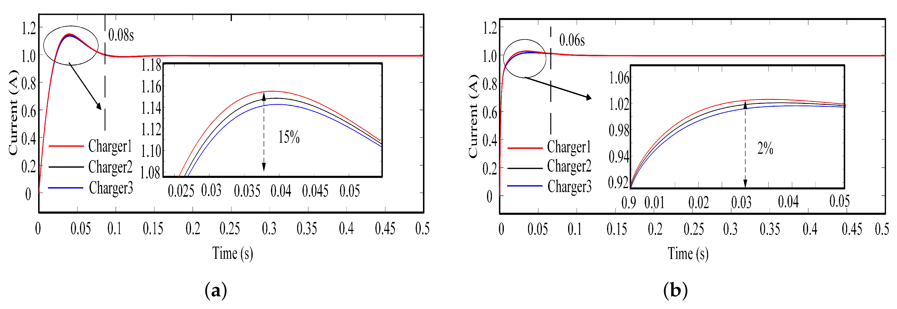
We will explore the capability of the proposed charging method. In order to make the experiment more accurate, we used MATLAB (Mathworks, Natick, USA) to perform model. We recorded the corresponding waveform diagrams and combined them with the experimental part below. We designed two sets of experiments for comparison. The first one is a classical second-order PI controller, and the other is the proposed method. We observe the waveform of the output signal and analyze it from the three perspectives of speed, stability, and accuracy.
Figure 3 shows the simulation results, which explores the effect of set point modulation on the charging process.
Figure 3a shows the simulation results of the classical charging method, where the overshoot is about 15%, the settling time is about 0.08 s.
Figure 3b shows the experiment results of the proposed method, where the current overshoot is about 2%, the settling time is about 0.06 s. The proposed charging method is faster than the classical charging method, and the overshooting can be restrained with the proposed charging method.
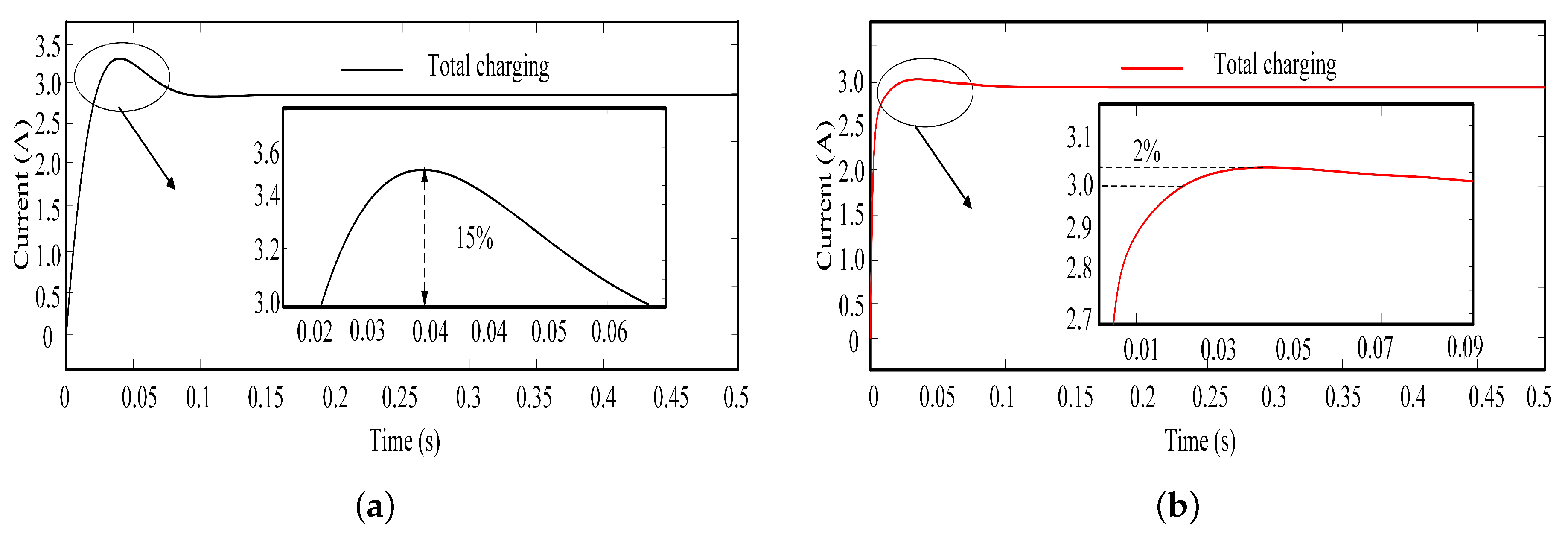
Figure 4 shows the simulation results of the two methods in total charging current.
Figure 4a shows the simulation results of the classical charging method, where the overshoot is about 15%, and the settling time is about 0.08 s.
Figure 4b shows the simulation results of the proposed charging method, where the overshoot is about 2%, and the settling time is about 0.06 s. Simulation results verify that the proposed charging method can restrain the current overshoot while reducing the settling time.
4.4. Hardware Setup
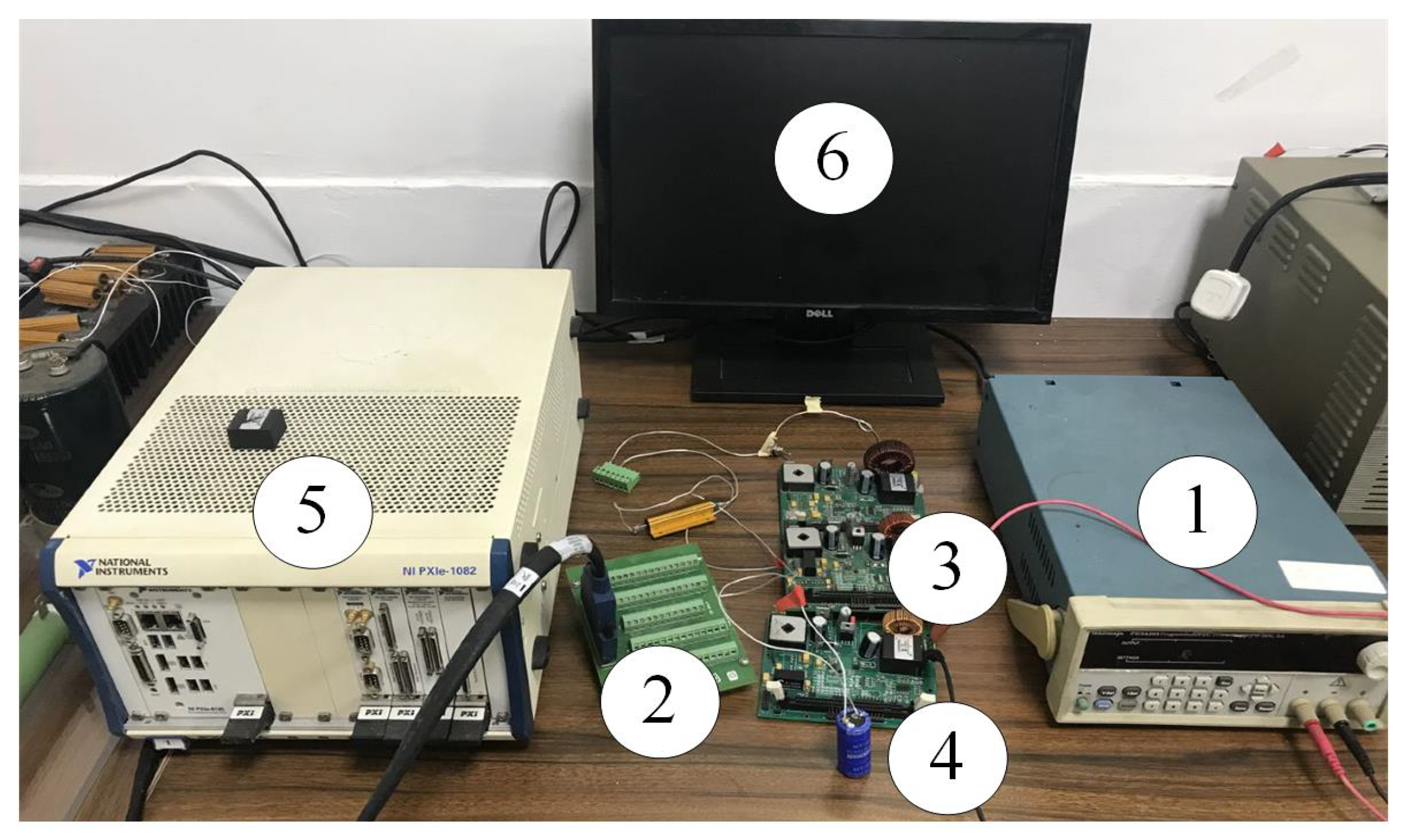
The hardware setup for this experiment is shown in
Figure 5. The main components of the test board are as follows
Power source. It provides 24 V voltage and can power three chargers.
Chargers. According to
Figure 1, design the buck circuit for this experiment. Each charger includes a buck regulator and voltage sensor, a PWM driver TLP700A, a current sensor CSM005A, filter chip TL074ID, a voltage transition chip PDUKE-24S05, and a TMS320F2808 microprocessor. The three chargers communicate with each other via the Controller Area Network (CAN) bus.
Ultracapacitor. We use the ultracapacitor battery as the load and use the output of the three chargers as the input. The model of the ultracapacitor is DP-2R5D607AA5, and its specific parameters are equivalent-serial-resistor (ESR) m and F.
PXI platform. Measure the current and voltage of the ultracapacitor through the PXI platform and use Labview to display the waveform on the computer.
The specific process of this experiment is as follows. The current sensor CSM005A is used to measure the current of the charger. The high-precision voltage divider is used to measure the output voltage of the charger. The low pass filter TL074ID filters the measured analog signal using TMS320F2808 microprocessor to process measured values. The three TMS320F2808 microprocessors communicate through the CAN module. Every controller produces a corresponding PWM signal to adjust the current and output voltage. The PXI platform is used to collect data, where the sampling frequency is 1 KHz.
4.5. Experiment Results
We experimentally proved the feasibility of this method. The experimental results are shown in
Figure 6,
Figure 7,
Figure 8 and
Figure 9, which are introduced as follows.
Figure 6 depicts the voltage variation of the ultracapacitor. After being fully charged, the charging process is disconnected, and the voltage of the ultracapacitor itself will cause a voltage drop of 15 mV. The steady-state current for each shipper is 1 A.
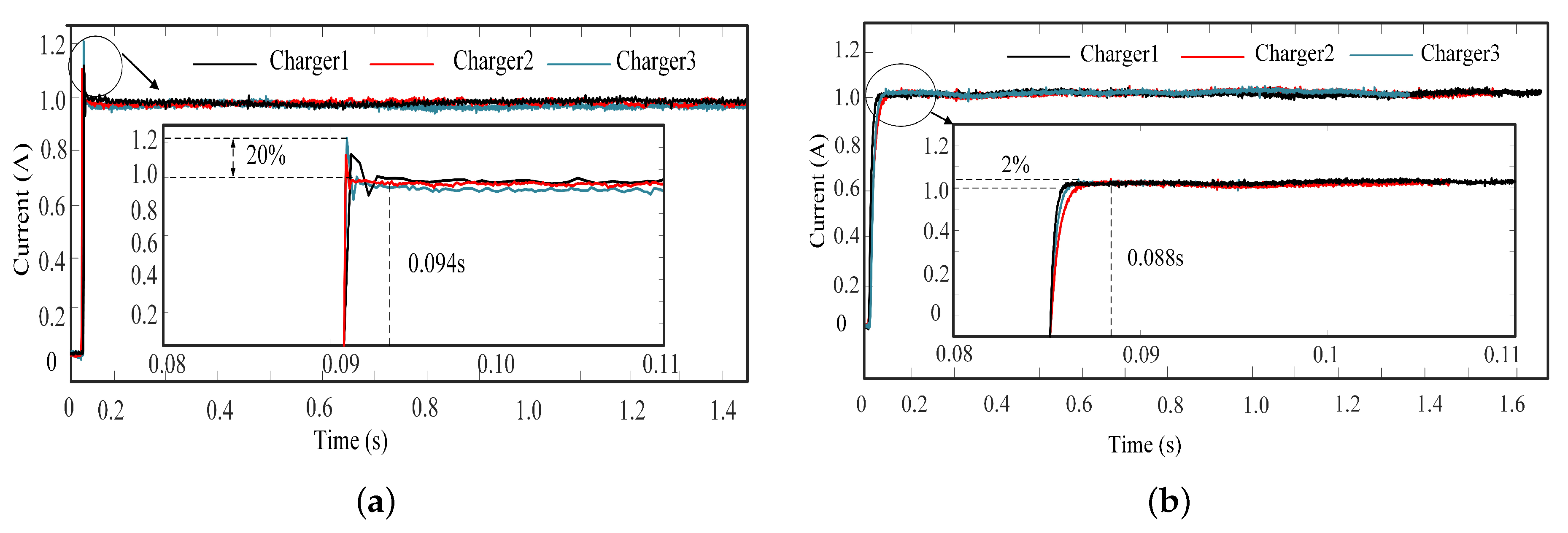
Figure 7 shows the experiment results, which explores the effect of set point modulation on the charging process.
Figure 7a shows the experiment results of the classical charging method, where the overshoot is about 20% and the settling time is about 0.094 s.
Figure 7b shows the experiment results of the proposed method, where the current overshoot is about 2% and the settling time is about 0.088 s.
Table 2 summarizes the experimental results of
Figure 7, from which it can be concluded that the proposed charging method can restrain the current while reducing the settling time.
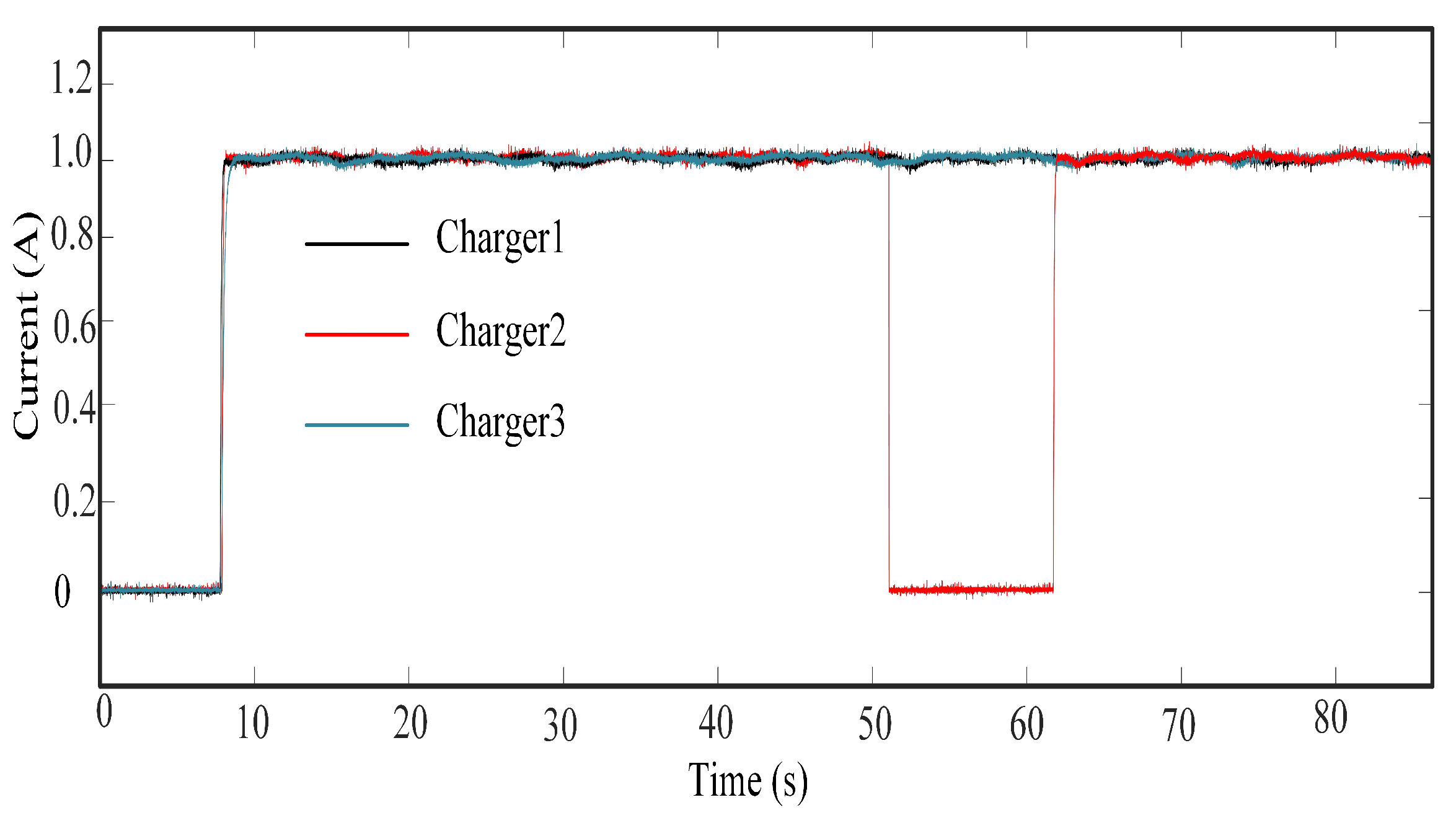
Figure 9 shows the fault tolerance of the system. When one charger encounters a failure, it will not affect other chargers, and after resuming charging, there will be no overshoot. In practical applications, it can effectively extend the life of chargers and ultracapacitors.
Figure 8 shows the experiment results of the two methods in total charging current.
Figure 8a shows the experiment results of the classical charging method, where the overshoot is about 15% and the settling time is about 0.094 s.
Figure 8b shows the experiment results of the proposed charging method, where the overshoot is about 2% and the settling time is about 0.088 s. Therefore, experiment results verify that the proposed charging method can restrain the current overshoot while reducing the settling time.
4.6. Result Discussions
We make the following comments about the proposed charging method.
4.6.1. Effectiveness
We can conclude from the two experimental results of
Figure 7 that the proposed charging method can restrain the current overshoot. The overshoot of the classical charging method and the proposed charging method is
and
, respectively. This is because the proposed method can adjust the reference value of the closed-loop system in time according to the actual output. When the expected output shows an excessive amount, the reference value is adjusted to a lower value to reduce the effect of overshoot.
4.6.2. Fault Tolerance
As shown in
Figure 9, when one charger fails, there will be no interference between chargers. When the charger is restored, the charger successfully prevents overshoot from occurring, which means that the proposed charging method is able to respond quickly to changes in dynamic conditions. This verifies the fault tolerance of the proposed method.
4.6.3. Practicality
In the process of charging ART vehicle, the charging current is very large. So a little overshoot will cause a very large current deviation, which will cause damage to the charger and super capacitor and reduce their service life. The proposed charging method can restrain the overshoot and has positive significance for extending the life of the charger and super capacitor.


