Article

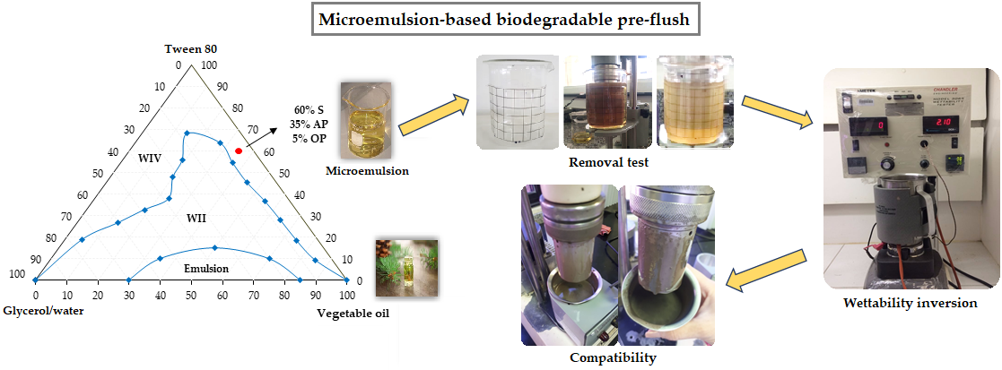
Application of Microemulsion Systems in the Formulation of Biodegradable Pre-Flush Fluid for Primary Cementing

by
Elayne A. Araújo
1,*,
Thaine T. Caminha
1,
Evanice M. Paiva
1,
Raphael R. Silva
1,
Júlio Cézar O. Freitas
2,
Alfredo Ismael C. Garnica
1 and
Fabíola D. S. Curbelo
1,*
1
Postgraduate Program in Chemical Engineering, Federal University of Paraiba, João Pessoa 58051-900, Brazil
2
Chemical Institute, Federal University of Rio Grande do Norte, Natal 59078-970, Brazil
*
Authors to whom correspondence should be addressed.
Energies 2020, 13(18), 4683; https://doi.org/10.3390/en13184683
Submission received: 3 July 2020 / Revised: 24 July 2020 / Accepted: 3 August 2020 / Published: 9 September 2020
(This article belongs to the Special Issue Advances in Drilling Fluid Technology)

Abstract

:
Oil well cleanup fluids (pre-flushes) are intermediate fluids pumped ahead of the cement slurry; they are able to clean the well walls by removing the filter cake formed by the drilling fluid, and leave the surface water-wet. This work’s main objective was to use biodegradable microemulsion systems as cleanup fluids in order to reduce the environmental impact. Three microemulsion systems were formulated, each composed of an oil phase, a surfactant and three different aqueous phases: glycerol, glycerol:water (mass ratio 1:1), and fresh water. The results show that all microemulsion systems were effective with 100% filter cake removal, with a removal time of less than 60 s. The wettability test and fluid compatibility analyses exhibited advantageous performances, without phase separation, variations in viscosity, gelation, or flocculation. The compressive strength and X-ray diffractometry (XRD) analysis showed the influence of the glycerol on the cement slurry properties, with the compressive strength resistance ranging from 8.0 to 10.7 MPa, and resulted in the formation of portlandite.

Graphical Abstract

1. Introduction

During the oil well cementing operation, it is necessary to remove contaminants such as the drilling fluid present in the wellbore wall. The contact between the drilling fluid and the cement slurry forms a viscous mixture, which results in poor drilling fluid displacement and weak cement placement [1,2,3]. To avoid such problems, intermediate fluids (pre-flushes or cleanup fluids) are often pumped to prevent or minimize the contact between them [4]. The cleanup fluids, pumped into the wellbore ahead of the cement slurry, are designed to displace the drilling mud from the annulus and make the annular surfaces water-wet [5,6,7].
The cleanup fluids applied in the petroleum industry for filter cake removal formed by non-aqueous drilling fluids (NAF) are basically composed of water, mutual solvent and/or acid, surfactants, or oil. Due to the presence of the highly flammable solvent, contact with the environment can cause serious damage. Some studies have shown the application of microemulsions and nanoemulsions in removing the filter cake formed by non-aqueous drilling fluids [8,9,10,11,12].
Microemulsions are basically composed of a mixture of two immiscible liquids—aqueous and oil phases, surfactants and/or cosurfactant—without the need for a high shear. In other words, they can be formulated with little or no mechanical energy input [13,14]. These systems are considered thermodynamically stable, transparent, or translucent, with low interfacial tension, due to the presence of surfactant compounds at the oil/water interface [15,16]. Previous research has shown the application of microemulsions can be used as cleanup fluids: to solubilize the oil present in the drilling mud [17]; in the filter cake removal and wettability inversion [9,10,11,12,18,19,20].
Therefore, this work aims to use microemulsion systems formulated from biodegradable components to reduce the environmental impact caused by conventional cleanup fluids. The microemulsion systems were formulated from ternary phase diagrams with vegetable oil (pine oil) as an oil phase; Tween 80 (T80) as a surfactant; and the aqueous phase varying among glycerol, aqueous glycerol solution (mass ratio 1:1) and fresh water. Moreover, we also analyzed the efficiency of the cleanup fluids in removing the filter cake formed by the drilling fluid, the wettability inversion from an oil-wet to a water-wet surface, and the compatibility among drilling fluid/cleanup fluid/cement slurry.

2. Materials and Methods

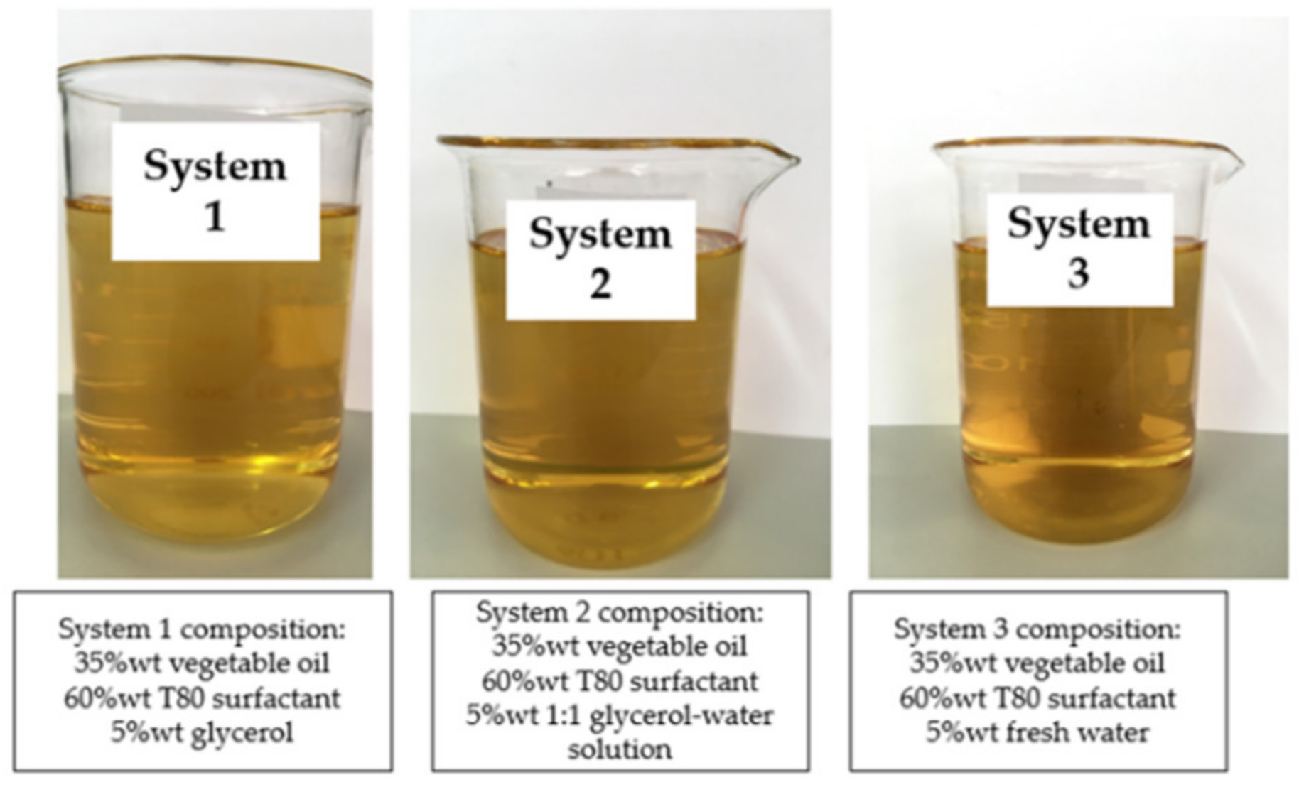
2.1. Microemulsion Systems

Through the ternary phase diagram, containing an aqueous phase, an oil phase, and a surfactant, it was possible to identify the formation of the microemulsion regions. The following components were used to elaborate on the ternary phase diagrams: glycerol, aqueous solution of glycerol (mass ratio 1:1), and fresh water as the aqueous phase (systems 1, 2 and 3, respectively); pine oil as the oil phase; Tween 80 (T80) as the surfactant, which is a nonionic biodegradable surfactant (polyoxyethylenesorbitan monooleate) produced by Dinâmica Química Contemporânea Ltda, Indaiatuba, SP, Brazil.

2.2. Removal Test

Microemulsion-based cleanup fluids were used to remove the filter cake formed by the drilling fluid. Following the test standard [21], 0.200 L of the microemulsion was prepared and heated at 361.15 K. The filter cake was formed by 4 × 10⁻³ L of drilling fluid film in a beaker. Olefinic-based drilling fluid, kindly provided by Petrobras, was homogenized in a Hamilton Beach mixer for 900 s (Table 1).
The drilling fluid was carefully distributed in a beaker until it fully covered the visualizing frame—composed of 66 squares of 10−4 m2 each—forming a uniform filter cake layer. Posteriorly, the microemulsion was added into the beaker to start the removal test on the Fann 35A viscometer, according to Procelab [22] at a maximum test time of 600 s. The cleanup fluid removal efficiency was then determined using Equation (1):
Removal efficiency = (number of squares removed × 1 × 10⁻⁴ m2/66 × 10−4 m2) × 100%

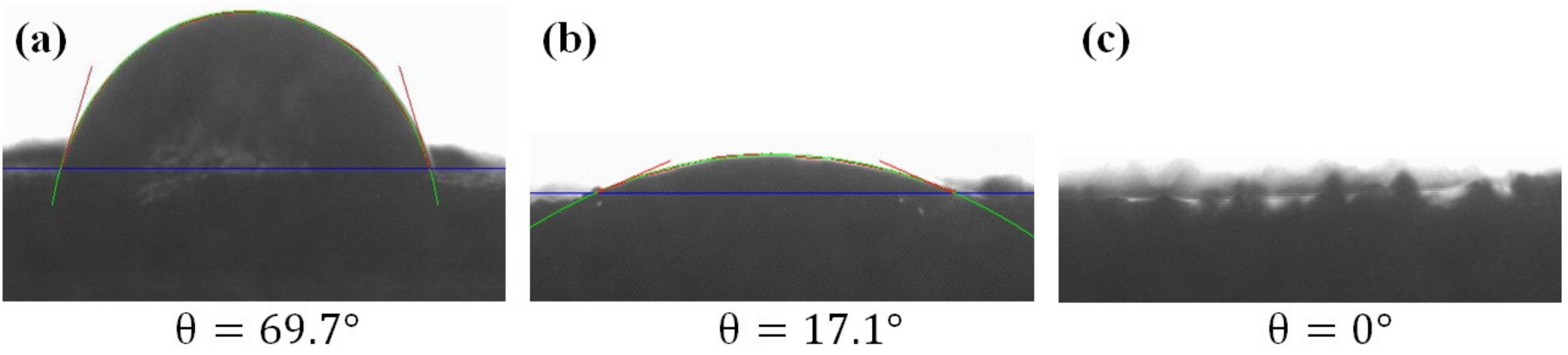
2.3. Wettability and Contact Angle Measurement

During the drilling fluid displacement using cleanup fluids, it is expected for the latter to alter the wettability of the rock formation. Due to this, the wettability was analyzed through the electrical conductivity and contact angle measurement.
The wettability inversion test was measured by continuously monitoring the electrical conductivity of the fluids, as they were subjected to heating and shearing at atmospheric pressure. The oil-based fluid was used to establish a reference conductance. The conditioned oil-based fluid was placed in the pre-heated mixer cup and stirred. The water-based fluid was then added until the digital conductivity meter indicated a stable water-wetting state. In addition to the digital display, the operator is able to visually ascertain the compatibility of the drilling mud and cleanup fluid during the test. The wettability inversion was measured in a wettability tester Chandler Model 3065, where it was possible to verify the volume of cleanup fluid used for the complete inversion.
The contact angle is considered the best method for analysing surface wettability and it accounts for the thermodynamic equilibrium between the fluid/rock system [23,24]. The adopted methodology was proposed by Wanderley Neto et al., 2019, Silva et al., 2020, and Dantas et al., 2014 [11,12,24]. The sandstone sample (plug) used in these experiments was from the Botucatu Formation (Paraná, Brazil). The Botucatu sandstone’s average porosity is 33%, and the permeability ranges from 2 × 10⁻¹⁵ to 8 × 10⁻¹⁵ m2. The plug was cut into rock disks with a 38 × 10−3 m diameter and 4.0 × 10⁻³ m length. Initially, the rock was saturated with the non-aqueous drilling fluid used in the previous experiments, then the same samples were immerged in the cleanup fluids. Both steps were carried out at room temperature (298.15 K) for 86,400 s. Finally, the samples were placed on a Krüss K100C Tensiometer and a drop of water was carefully transferred to their surface, and then the contact angle between the rock and the water was measured.

2.4. Fluid Compatibility Test

The compatibility study of the drilling fluid, cleanup fluid and the cement slurry was carried out according to API testing recommendations, because an incompatibility could result in phase separation, sedimentation of solids, cleanup and wettability inversion inefficiency, and fluid destabilization [19]. The test was performed in the proportions (v/v) of 95/5, 75/25, 50/50, 25/75 and 5/95 for cleanup fluid/non-aqueous drilling fluid or cement slurry, and in 25/50/25 (v/v/v) for non-aqueous drilling fluid/cleanup fluid/cement slurry. The rheological behaviors were observed in a Fann 35 viscometer.
The cement slurry was prepared using fresh water and special class A Portland cement (NBR 9831, 2006), used in oil well cementing and preconditioned according to API RP 10B-2 (2013). The composition of the cement paste is shown in Table 2.

2.5. Influence of Cleanup Fluid on the Performance of Cement Slurries

This experiment was carried out on an ultrasonic cement analyzer (UCA), Model 4262, Chandler Engineering, with the objective of simulating the compressive strength of the cement slurry contaminated with cleanup fluids when pumped in an oil well. Standard slurry (STD) containing only cement and water, and other cement slurries contaminated with 1:9 (cleanup fluid/cement) were prepared according to API RP 10B-2, 2013, and the established conditions were 418.7 K, 20.7 MPa for 86,400 s.

2.6. Analysis of Cement Slurries Contamination Using X-ray Diffractometry (XRD)

X-ray techniques were performed to verify the influence of the cement slurries contaminated by the microemulsion systems, using equipment from Bruker, Eco D8 Advance with Cu Kα radiation X-ray tube. The scan was done at a range of 5°–80° with an increase of 0.03°, a step time of 0.3 s, and a rotation of 0.25 s−1 was applied on the sample holder. The software used in the identification was the EVA from Bruker, designed to determine the presented phases.

3. Results

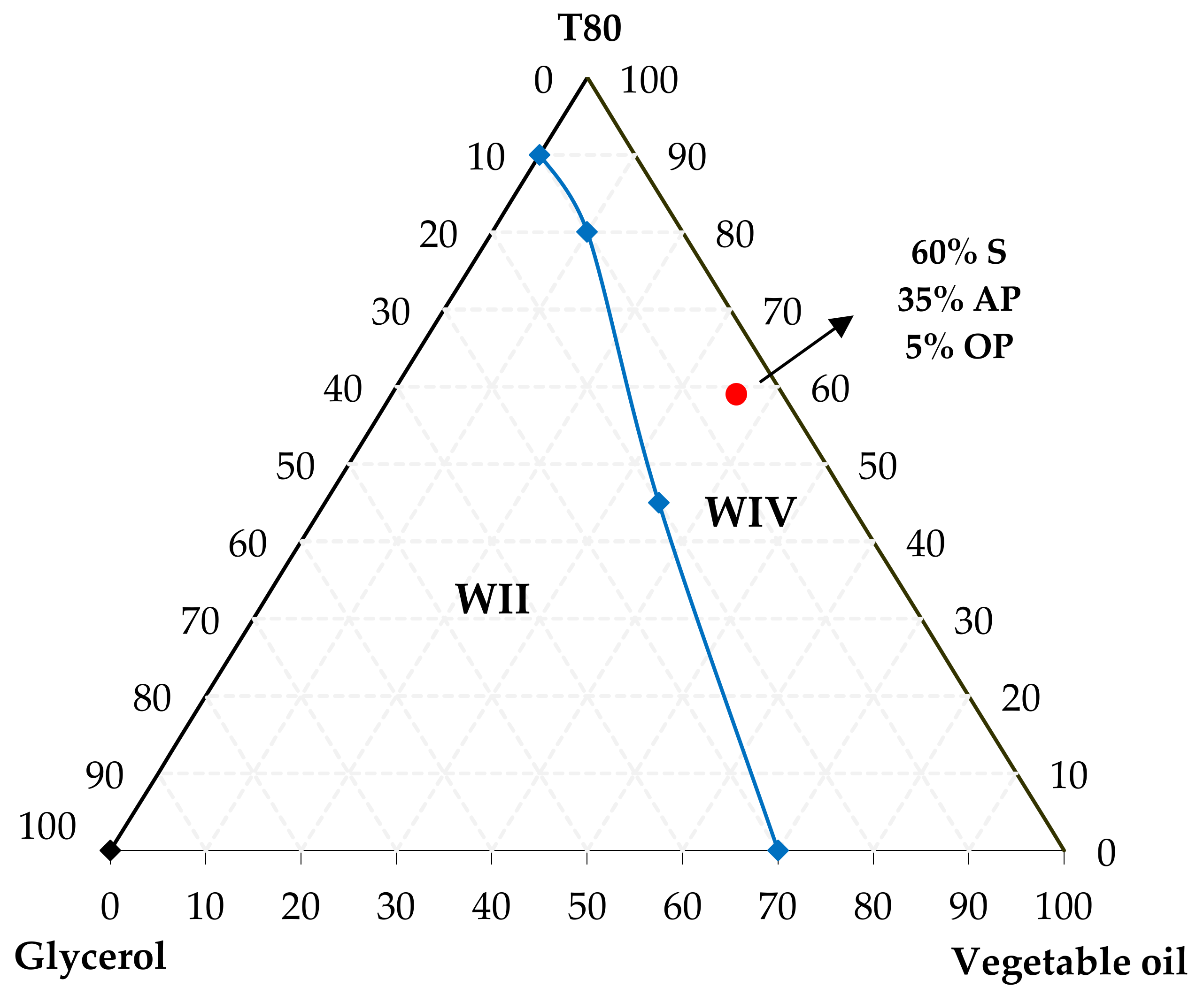
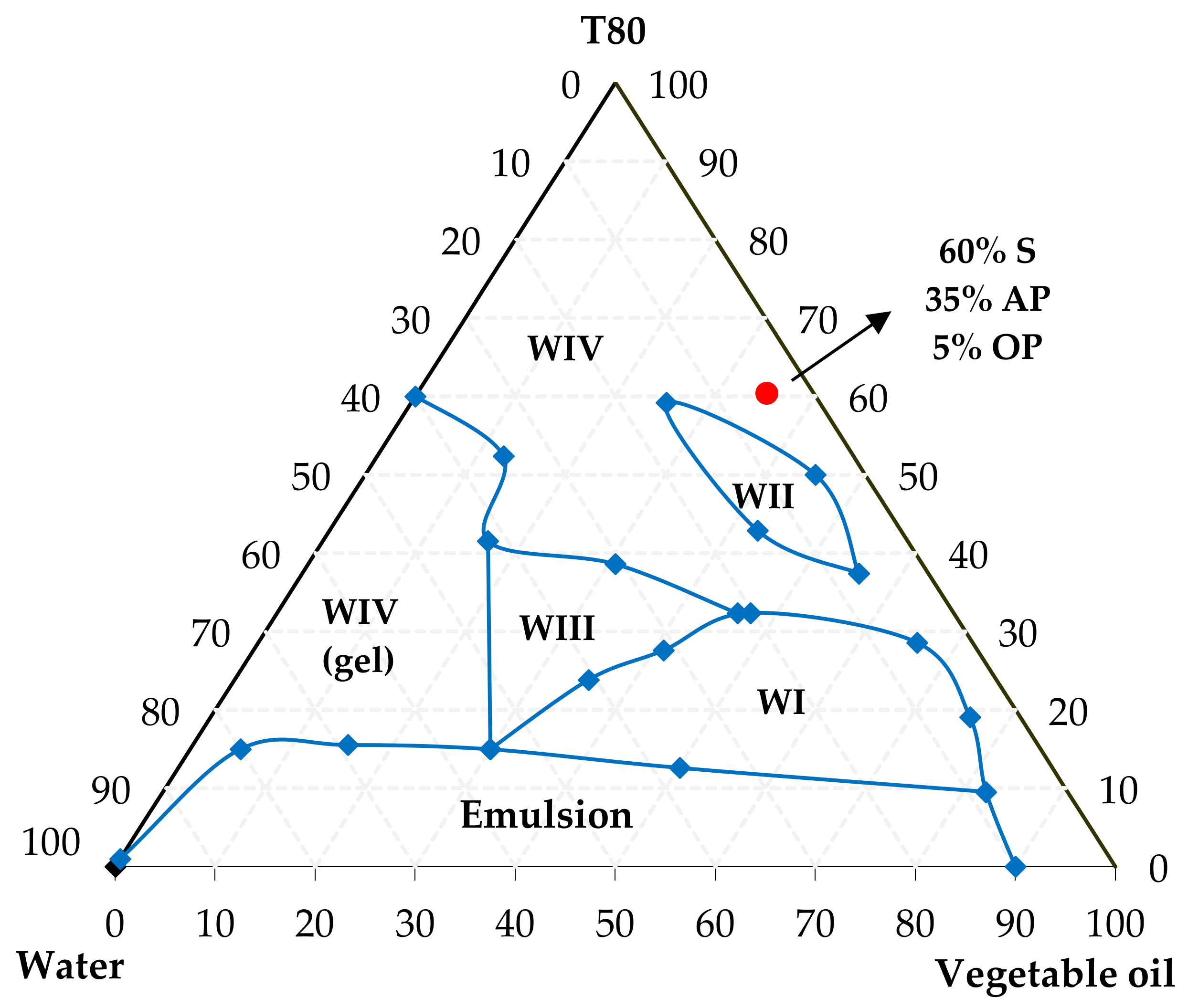
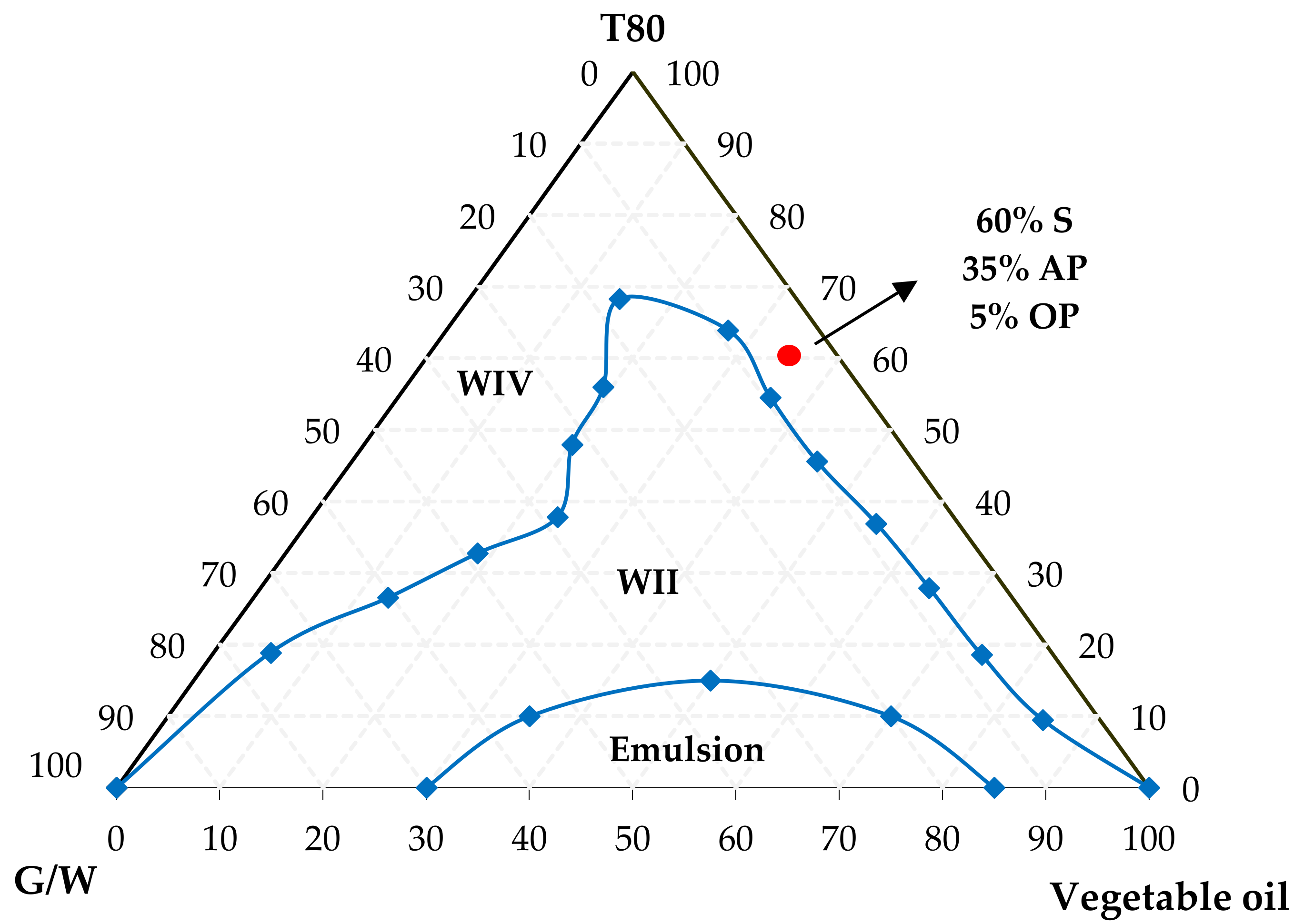
3.1. Microemulsion Systems: Ternary Phase Diagrams

Three different ternary phase diagrams were developed. The ternary point corresponding to 60 wt.% surfactant, 35 wt.% aqueous phase and 5 wt.% oil phase was used for the formulation of the three systems. System 1 is composed of glycerol, T80 surfactant and vegetable oil; system 2 consists of the glycerol/water solution (1:1), T80 surfactant and vegetable oil; and system 3 consists of fresh water, T80 surfactant and vegetable oil, as shown in Figure 1, Figure 2 and Figure 3, respectively. These diagrams show the microemulsion (ME), emulsion and multiphase regions.
Figure 1 refers to system 1 and presents two regions classified according to Winsor (1954) as Winsor II (WII) and Winsor IV (WIV). The Winsor II (WII) region is a water-in-oil microemulsion (W/O), and the Winsor IV (WIV) region consists of a single-phase microemulsion.
The glycerol (1, 2, 3 propanetriol) owns three hydroxyl groups in its constitution, and it gives the characteristic of a highly soluble substance in water and alcohol. The T80 is a nonionic surfactant, and it presents an HLB value (hydrophilic lipophilic balance) of 15, which characterizes it as a soluble-in-water substance. However, due to its viscosity, it was not possible to solubilize the glycerol. In order to increase the solubility of the glycerol in the surfactant, a glycerol/water (1:1 v/v) solution was made (Figure 2).
According to Figure 2, the addition of water to the glycerol reduced the solution‘s viscosity and provided greater solubility with the surfactant. From the diagram, it is possible to verify the appearance of an emulsion region, which normally appears when the surfactant concentration is below the critical micelle concentration (CMC), and it is not enough to solubilize the immiscible liquids (aqueous phase and oil phase).
It is observed from Figure 3 (system 3) that different regions were obtained: Winsor I (WI); Winsor II (WII); Winsor (III), that it is a triphasic region (aqueous and oil phase in equilibrium with the microemulsion); Winsor WIV (WIV); Winsor IV and gel; and, emulsion [25]. Figure 3 showed a greater microemulsion region (WIV) than the other diagrams. This occurred because the surfactant is highly hydrophilic, and therefore, the T80 surfactant exhibited greater solubility with only fresh water in the aqueous phase. The three microemulsified systems with the chosen composition are shown in Figure 4.

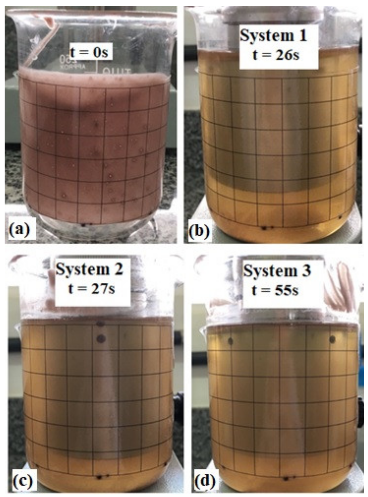
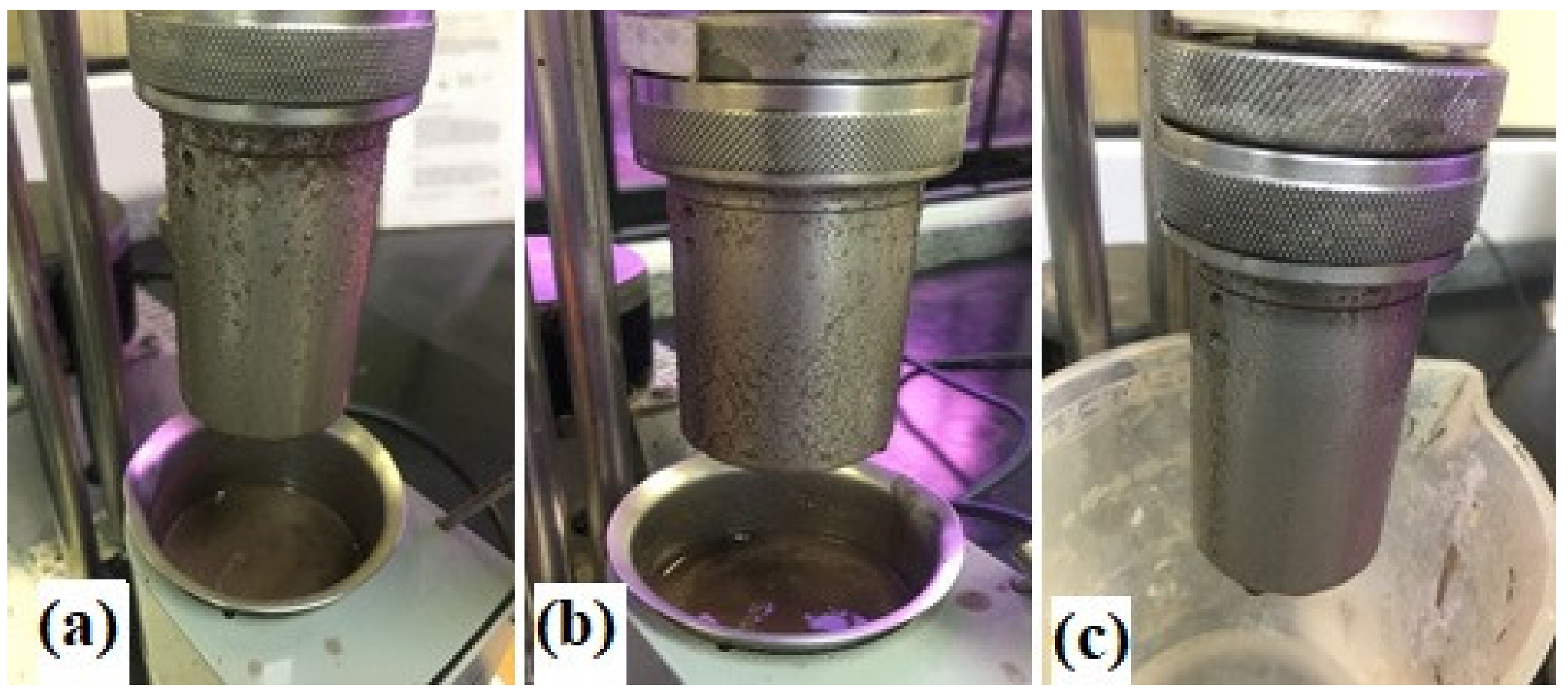
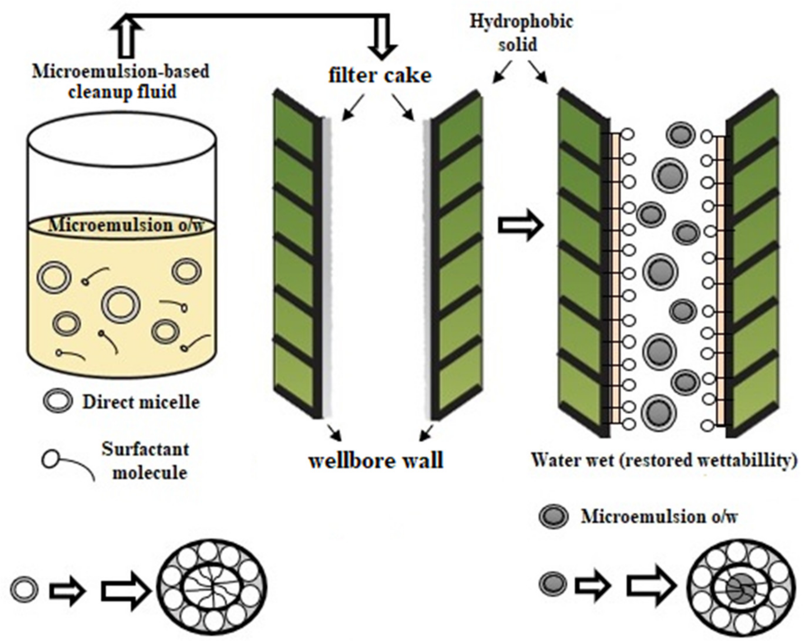
3.2. Filter Cake Removal Test

The removal of the filter cake was evaluated by pouring a thin layer of NAF (Figure 5a) into a beaker and then carefully pouring the microemulsion into the recipient to completely clean the residue. It is possible to verify that all systems obtained 100% of NAF removal after less than 60 s (Figure 5b–d).
Notably, the three systems were very effective; however, it is possible to verify (Figure 5b,c) a slight better efficiency of systems 1 and 2 when compared with system 3 (Figure 5d), probably because this system only has fresh water in its aqueous phase, which took a little longer to remove the NAF.

3.3. Wettability Test

Table 3 shows that all cleanup fluids were able to promote a wettability inversion of the NAF filter cake.
For the three studied systems, the inversion test results are quite satisfactory. According to the API standard [21], 0.200 L of drilling fluid must be used, and for a cleaner fluid to be effective, in addition to inverting the rock‘s wettability, the used cleaner fluid volume should be equal to or less than 0.200 L. Table 3 shows that the three systems used cleaner fluid volumes much smaller than 0.200 L.
Since the non-aqueous drilling fluid consists of water droplets dispersed in a continuous oil phase, when the cleanup fluid encounters the drilling fluid, the mud emulsion will absorb water until the water droplets become so large that the external oil layer can no longer contain them, so the emulsion breaks, and the surface becomes water-wet [26], as shown in Figure 6.
Figure 7 shows the immediate contact angle. Figure 7a shows the immediate contact angle of the rock saturated with the NAF, Figure 7b shows the immediate contact angle after treatment with system 1, and Figure 7c for systems 2 and 3. The results indicate that the microemulsified systems 2 and 3 presented a smaller contact angle (θ = 0°) compared with system 1 (θ = 17.1°) and they showed a consistent result with values found in the literature [13].
A low contact angle with the reservoir rock is an important property of microemulsion fluids for these applications. These properties generate good organic material cleaning with minimum mechanic energy [27,28]. It is also noted that the water wettability of the rock, after treatment with the microemulsions, increased with all systems.

3.4. Compatibility Test

Figure 8, Figure 9 and Figure 10 show shear stress (τ) as a function of shear rate (γ) for the cement slurry, pure cleanup fluid, and the mixtures of cement slurry/cleanup fluid for the systems 1, 2 and 3, respectively.
The cleanup fluids exhibit rheological behavior near to water or oil phases [5]. These products act by diluting and dispersing the NAF, in addition to leaving the surfaces water-wet. Therefore, by analyzing the studied systems, it is possible to observe that there was a decrease in the viscosity of the mixture, which presented a lower viscosity than the cement slurry, indicating that there were no peaks of variation in the mixture’s viscosity. These results are satisfactory because according to [29], two or more fluids are compatible when the rheological measurements of mixtures are between the readings of pure fluids.
The compatibility test is also obtained when these fluids (cleanup, NAF and cement), mixed in different proportions, do not present undesirable chemical or physical reactions, according to the API testing recommendations [21] (Figure 11, Figure 12 and Figure 13).
Hence, Figure 14 shows that there was compatibility between the fluids. It is possible to observe that there was no phase separation, excessive viscosity, gelation, flocculation, settling or hardening of the mixture, thus indicating that the formulated fluids are compatible both with the NAF and the cement slurry.

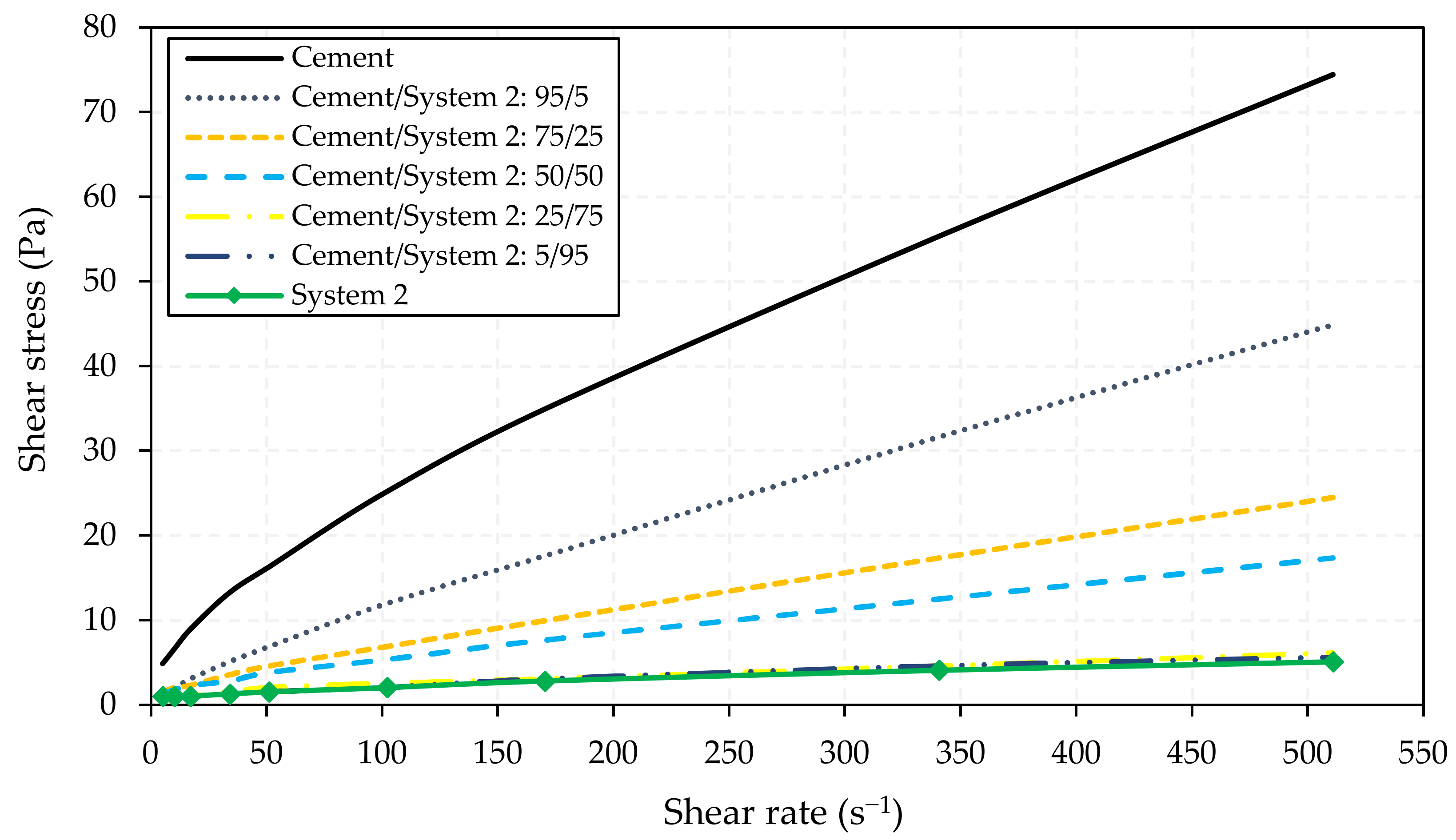
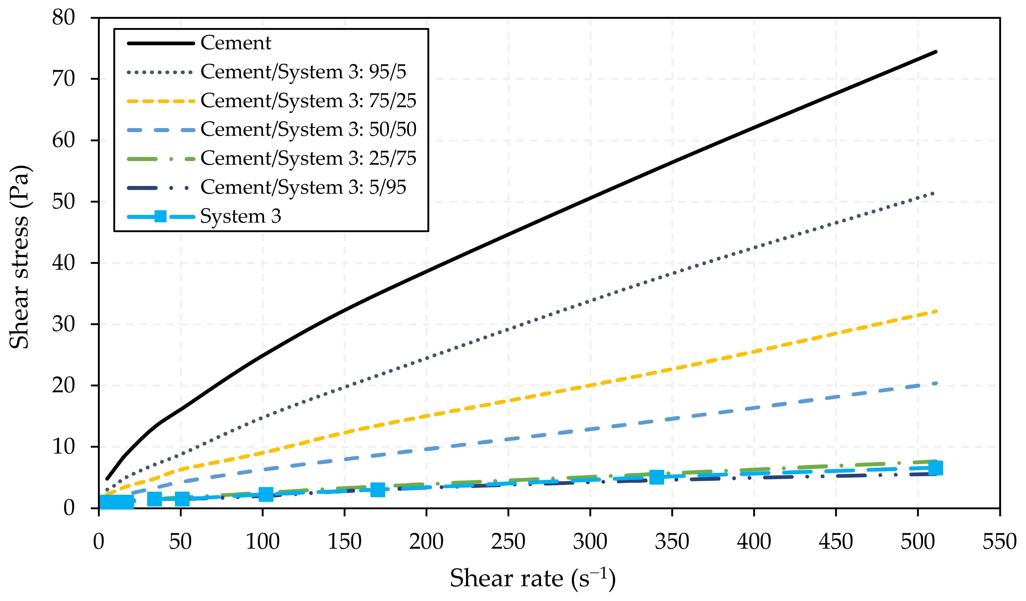
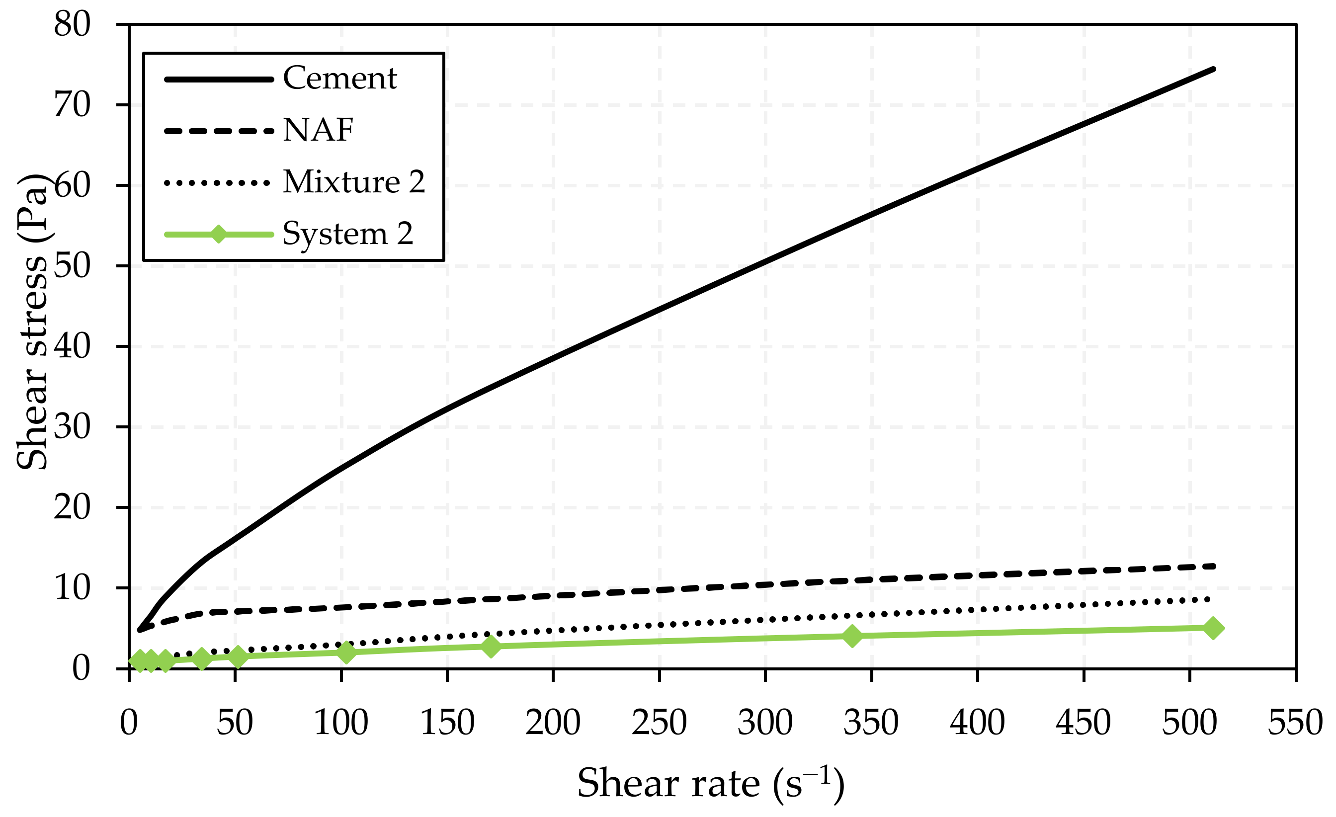
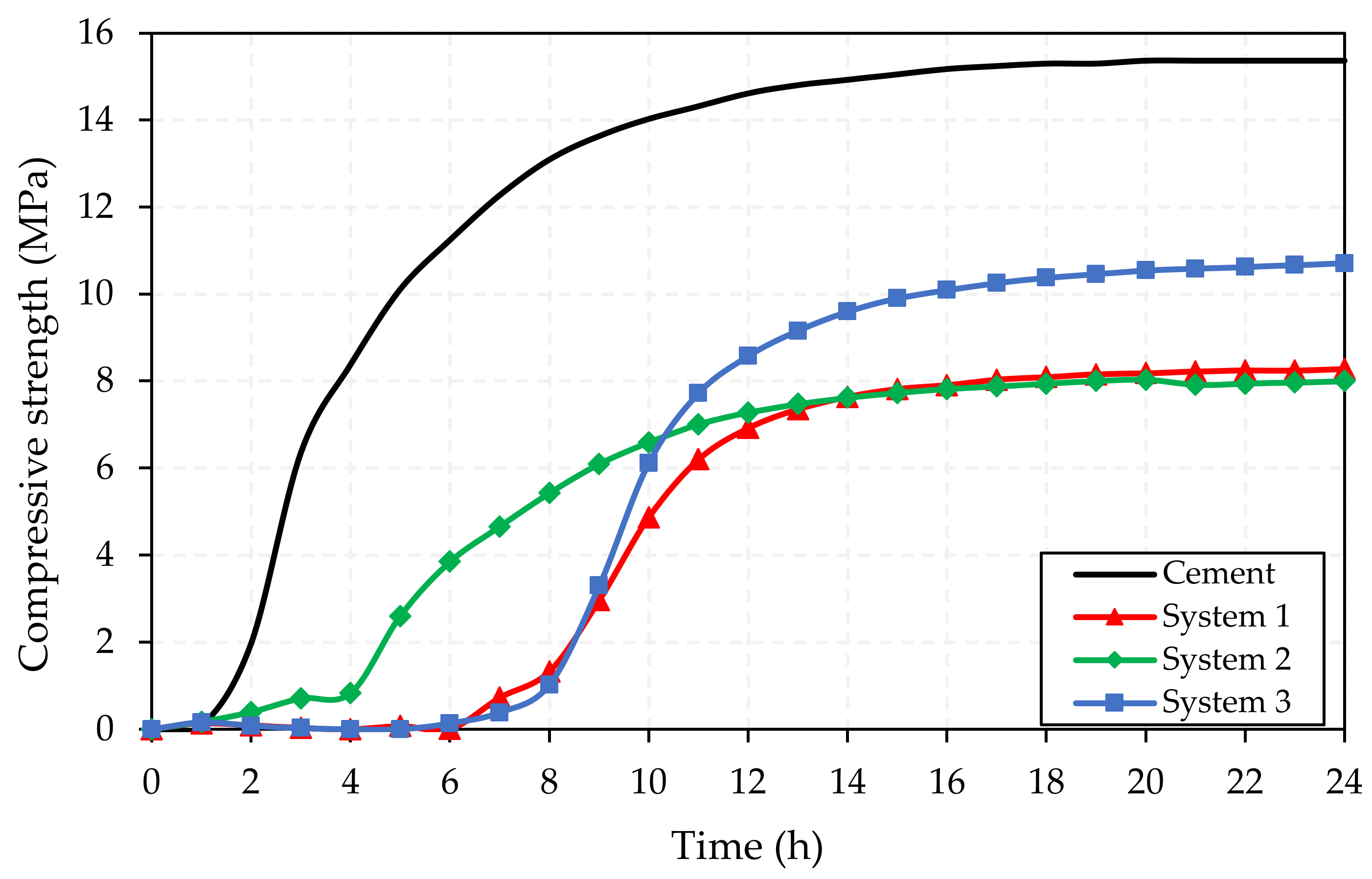
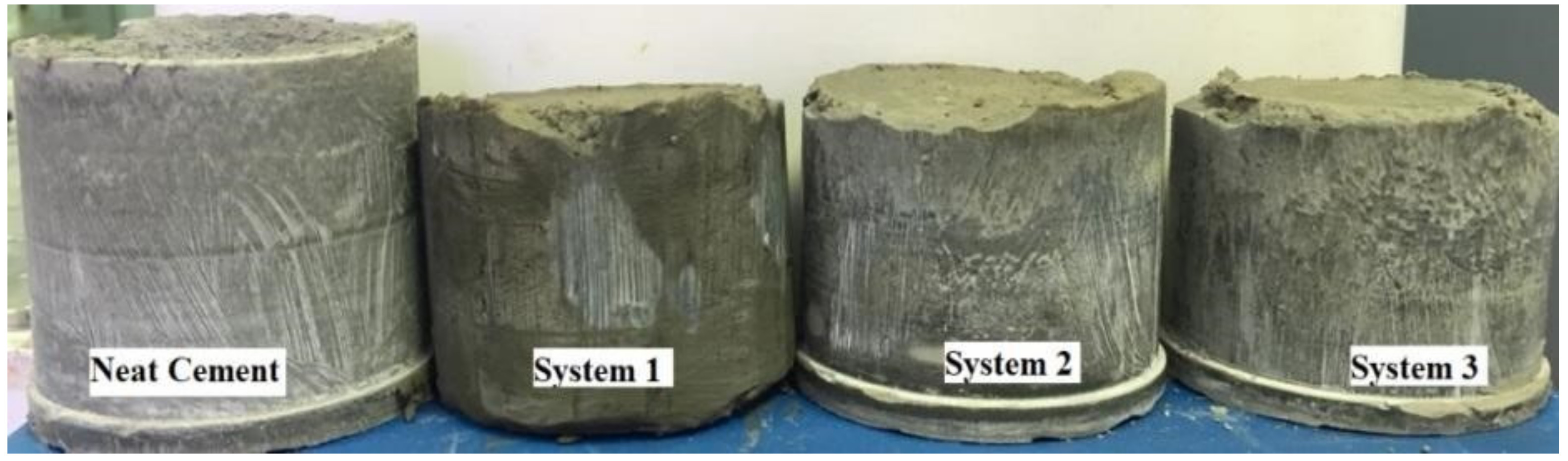
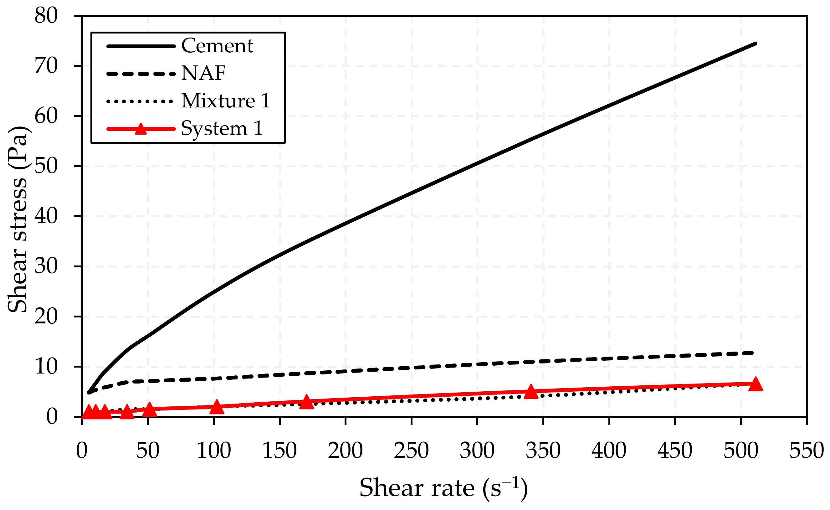
3.5. Influence of Cleanup Fluid on the Performance of Cement Slurries

According to Figure 15, the compressive strength of the cement slurry (STD) was approximately 15 MPa, whereas the cement slurries contaminated with cleanup fluids, in the proportions 1:9 (v/v) (cleanup fluid/cement), presented lower results. System 1, containing only glycerol, presented a resistance of 8.3 MPa, a decrease of 45%. System 2 (aqueous phase—water and glycerol) showed a result near to system 1’s resistance, which was about 8 MPa. System 3, because it only had water, had a resistance of 10.7 MPa, a decrease of only 29%. The results are in accordance with what we expected, since compressive strengths greater than 3.4 MPa (500 psi) were obtained, which favors good zonal isolation [28].
According to [30], establishing cement as a barrier and achieving zonal isolation behind the casing is one of the main goals in any drilling operation. Thus, aiming to continue establishing the structure, it can be concluded that the three systems were satisfactory, as none of them displayed a significant drop in the compressive strength.
The morphology of the pure cement and cement slurries contaminated by the cleanup fluid are shown in Figure 16. There was not any formation of microcavities after the curing time (24 h), which shows that there was no physical interference in the structure of the samples, guaranteeing the performance of the cement in the wellbore wall.

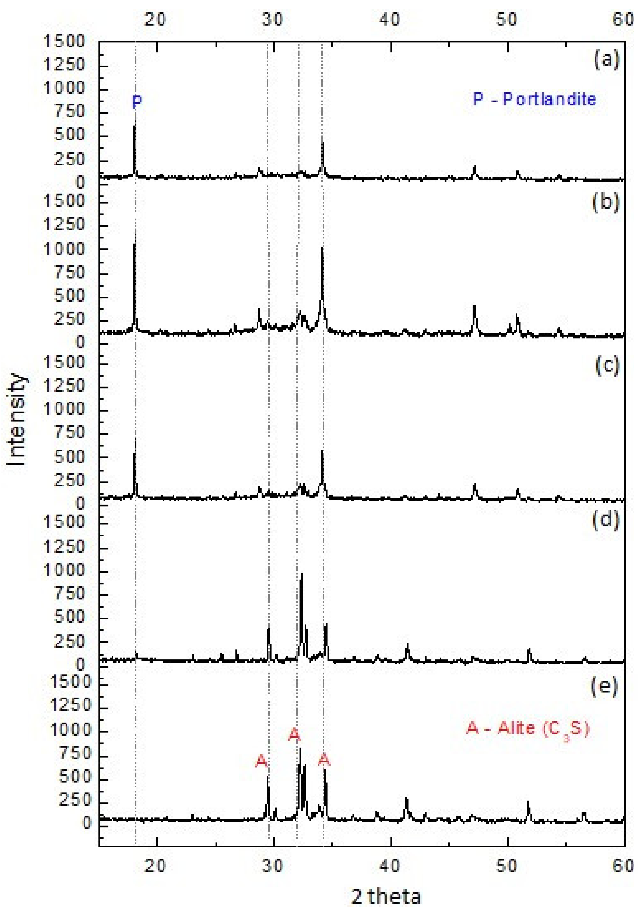
3.6. X-Ray Diffractometry (XRD)

In order to show the phases’ formation, the study considered the samples’ crystallographic evaluation through the X-ray diffraction technique. Figure 17 presents the diffractograms of each sample evaluated: standard slurry (STD) (a), cement slurry/system 1 (d), cement slurry/system 2 (c), cement slurry/system 3 (b), and anhydrous cement (e). The mixed cement slurries evaluated—in the proportions 1:9 (v/v) (cleanup fluid/cement)—were obtained from the compressive strength test.
Figure 17 shows the diffractogram peaks related to the hydrated phases common to Portland cement. The main phase was portlandite Ca(OH)2, whose peaks have a greater intensity in samples (a), (b) and (c), due to the presence of water in these samples, generating this hydration product.
System 1 (diffractogram d) and anhydrous cement (diffractogram e) are samples without water, and therefore the portlandite peaks did not arise in the diffractograms and, consequently, more alite (C3S) appeared in the diffractograms of these samples, which is indicative of non-hydrating behavior. The reaction with water occurs according to Equation (2).
2 Ca3SiO5 (alite) + 6 H2O → C-S-H + 3 Ca (OH)2
The glycerol present in system 1 is slightly viscous and the sample avoided hydration of the cement paste, consequently, reducing the compressive strength of the systems 1 (only glycerol) and 2 (glycerol/water) in relation to system 3 (only fresh water) (Figure 15).

4. Conclusions

The cleanup fluids formulated in this work are considered eco-friendly and can eliminate the use of toxic agents commonly used in completion operations. At the same time, they meet all the prerequisites required for those products, which are: (1) the studied systems presented good percentages of filter cake removal, in which the system composed with glycerol presented greater removal efficiency in less time; (2) all the systems were effective in the wettability inversion, and the glycerol-based microemulsion, as cleanup fluid, can better promote the change in the wellbore wall from oil-wet into water-wet, which is desirable to promote the quality of cementation; (3) the cement slurry contaminated with microemulsions showed a slight decrease in the compressive strength with the addition of glycerol; (4) systems composed of glycerol/water are better for application as cleanup fluid or pre-flushes, providing a cleaner technology in order to reduce environmental pollution.

Author Contributions

In this work, authors E.A.A., T.T.C., E.M.P., R.R.S., J.C.O.F., A.I.C.G. and F.D.S.C., contributed equally to each section of this paper. All authors have read and agreed to the published version of the manuscript.

Funding

This research received no external funding.

Acknowledgments

This work was performed at Petroleum Laboratory (LaPet), Department of Chemical Engineering, Federal University of Paraíba (UFPB) and Núcleo Tecnologico em Cimentação de Poços de Petroleo (NTCPP) of Federal University of Rio Grande do Norte (UFRN). The authors thank to FAPESQ/CAPES and PIBIC/UFPB by scholarship granted supports (no grant number), the Laboratory of Cement (UFRN), and Postgraduate Program of Chemical Engineering/PPGEQ/UFPB.

Conflicts of Interest

The authors declare no conflict of interest.

References

  1. Bishop, M.; Moran, L.; Stephens, M.; Reneau, W. A robust, field friendly, cement spacer system. In Proceedings of the AADE Fluids Conference and Exhibition, Houston, TX, USA, 8–9 April 2008. [Google Scholar]
  2. Zhang, Z.; Scherer, G.W.; Prud’Homme, R.K. Adhesion and bonding between steel pipe and cement/spacer/mud system. In Proceedings of the 9th International Conference on Fracture Mechanics of Concrete and Concrete Structures, Berkeley, CA, USA, 22–25 May 2016. [Google Scholar] [CrossRef]
  3. Zhang, Z.; Scherer, G.W.; Prud’Homme, R.K.; Choi, M. Effect of casing surface roughness on the removal efficiency of non-aqueous drilling fluids. J. Nat. Gas Sci. Eng. 2018, 51, 155–165. [Google Scholar] [CrossRef]
  4. Mcclure, J.; Khalfallah, I.; Taoutaou, S.; Bermea, J.A.V.; Kefi, S. New cement spacer chemistry enhances removal of nonaqueous drilling fluid. J. Petrol. Technol. 2014, 15–32. [Google Scholar] [CrossRef]
  5. Nelson, E.B.; Guillot, D. Well Cementing; Schlumberger: Houston, TX, USA, 2006; p. 773. [Google Scholar]
  6. Pietrangeli, G.; Quintero, L. Enhanced oil solubilization using microemulsion with linkers. In Proceedings of the SPE International Simposium on Oilfield Chemistry, The Woodlands, TX, USA, 8–10 April 2013. [Google Scholar] [CrossRef]
  7. Pernites, R.; Khammar, M.; Santra, A. Robust spacer system for water and oil based mud. In Proceedings of the SPE Western Regional Meeting, California, CA, USA, 27–30 April 2015. [Google Scholar] [CrossRef]
  8. Wang, C.; Meng, R.; Xiao, F.; Wang, R. Use of nanoemulsion for effective removal of both oil-based drilling fluid and filter cake. J. Nat. Gas Sci. Eng. 2016, 36, 328–338. [Google Scholar] [CrossRef]
  9. Curbelo, F.D.S.; Garnica, A.I.C.; Araujo, E.A.; Paiva, E.M.; Cabral, A.G.; Araujo, E.A.; Freitas, J.C.O. Vegetable oil-based preflush fluid in well cementing. J. Petrol. Sci. Eng. 2018, 170, 392–399. [Google Scholar] [CrossRef]
  10. Curbelo, F.D.S.; Caminha, T.T.; Garnica, A.I.C.; Melo, G.N.A.; Araújo, E.A.; Freitas, J.C.O. Microemulsion-based flushing fluid for effective removal of filter cake in wells cementation. Bra. J. Petrol. Gas 2019, 13, 119–127. [Google Scholar] [CrossRef]
  11. Wanderley Neto, A.O.; Silva, V.L.; Rodrigues, D.V.; Ribeiro, L.S.; Silva, D.N.N.; Freitas, J.C.O. A novel oil-in-water microemulsion as a cementation flushing fluid for removing nonaqueous filter cake. J. Petrol. Sci. Eng. 2019, 184. [Google Scholar] [CrossRef]
  12. Silva, D.C.; Araújo, C.R.B.; Freitas, J.C.O.; Rodrigues, M.A.F.; Wanderley Neto, A.O. Formulation of new microemulsion systems containing produced water for removal of filter cake from olefin-based drilling fluid. J. Petrol. Sci. Eng. 2020. [Google Scholar] [CrossRef]
  13. Brege, J.; Sherbeny, W.E.; Quintero, L.; Jones, T. Using microemulsion technology to remove oil-based mud in wellbore displacement and remediation applications. In Proceedings of the North Africa Technical Conference and Exhibition, Cairo, Egypt, 20–22 February 2012. [Google Scholar] [CrossRef]
  14. Zanten, R.V.; Lawrence, B.; Henzler, S. Using surfactant nanotechnology to engineer displacement packages for cementing operations. In Proceedings of the IADC/SPE Drilling Conference and Exhibition, New Orleans, LA, USA, 2–4 February 2000. [Google Scholar] [CrossRef]
  15. Schulman, J.H.; Stoeckenius, W.; Prince, L.M. Mechanism of formation and structure of micro emulsions by electron microscopy. J. Phys. Chem. 1959, 63, 1677–1680. [Google Scholar] [CrossRef]
  16. Danielsson, I.; Lindman, B. The definition of microemulsion. Colloids Surf. 1981, 3, 391–392. [Google Scholar] [CrossRef]
  17. Quintero, L.; Christian, C.; Halliday, W.; White, C.; Dean, D.; Courtney, G. New spacer technology for cleaning and water wetting of casing and riser. In Proceedings of the AADE-08- DF-HO-01, Houston, TX, USA, 8–9 April 2008. [Google Scholar]
  18. Pietrangeli, G.; Quintero, L.; Gonzalez, Y. In-situ microemulsions enhance removal of non-aqueous drilling fluid in gulf of Guinea Wells. In Proceedings of the SPE European Formation Damage Conference and Exhibition, Budapest, Hungary, 3–5 June 2015. [Google Scholar] [CrossRef]
  19. Darugar, Q.; Quintero, L.; Christian, C.F.; Ellis, D.R. Fluorescence microscopy: A technique to study and evaluate spacer fluids for wettability inversion. In Proceedings of the AADE Fluids Conference and Exhibition, Houston, TX, USA, 6–7 April 2010. [Google Scholar]
  20. Maserati, G.; Daturi, E.; Gaudio, L.D.; Belloni, A.; Bolzoni, S.; Lazzari, W.; Leo, G. Nano-emulsions as cement spacer improve the cleaning of casing bore during cementing operations. In Proceedings of the SPE Annual Technical Conference and Exhibition, Florence, Italy, 19–22 September 2010. [Google Scholar] [CrossRef]
  21. American Petroleum Institute (API). Recommended Practice for Testing Well Cements; API RP 10B-2; American Petroleum Institute (API): Washington, DC, USA, 2013. [Google Scholar]
  22. Campos, G. PROCELAB—Procedimentos e métodos de laboratório destinados à cimentação de poços de Petróleo (Procedures and methods laboratory for cementing of oil wells). Rio de Janeiro. 2014, 12, 1–3. [Google Scholar]
  23. Alotaibi, M.B.; Nasralla, R.A.; Nasr-El-Din, H.A. Wettability challenges in carbonate reservoirs. In Proceedings of the SPE Improved Oil Recovery Symposium, Tulsa, OK, USA, 24–28 April 2010. [Google Scholar] [CrossRef]
  24. Dantas, T.N.C.; Soares A, P.J.; Wanderley Neto, A.O.; Dantas Neto, A.A.; Barros Neto, E.L. Implementing new microemulsion systems in wettability inversion and oil recovery from carbonate reservoirs. Energy Fuels 2014, 28, 6749–6759. [Google Scholar] [CrossRef]
  25. Winsor, P.A. Solvent Properties of Amphiphilic Compounds; Butterworth: London, UK, 1954. [Google Scholar]
  26. Heathman, J.; Wilson, J.M.; Cantrell, J.H.; Gardner, C. Removing subjective judgment from wettability analysis aids displacement. In Proceedings of the IADC/SPE Drilling Conference, New Orleans, LA, USA, 23–25 February 2000. [Google Scholar] [CrossRef]
  27. Brege, J.J.; Pietrangeli, G.; McKellar, A.J.; Quintero, L.; Forgiarini, A.; Salager, J. Fluid formulations for cleaning oil-based or synthetic oil-based mud filter cakes. U.S. Patent US20150087563 A1, 26 March 2015. [Google Scholar]
  28. Quintero, L.; Passanha, W.D.; Aubry, E.; Poitrenaud, H. Advanced microemulsion cleaner fluid applications in deepwater wells. In Proceedings of the OTC Brasil, Rio de Janeiro, Brazil, 27–29 October 2015. [Google Scholar] [CrossRef]
  29. Shadravan, A.; Narvaez, G.; Alegria, A.; Carman, P.; Perez, C.; Erger, R. Engineering the mud-spacer-cement rheological hierarchy improves wellbore integrity. In Proceedings of the SPE E&P Health, Safety, Security and Environmental Conference-Americas, Denver, CO, USA, 16–18 March 2015. [Google Scholar] [CrossRef]
  30. Li, M.; Ou, H.; Li, Z.; Gu, T.; Liu, H.; Guo, X. Contamination of cement slurries with diesel based drilling fluids in a shale gas well. J. Nat. Gas Sci. Eng. 2015, 27, 1312–1320. [Google Scholar] [CrossRef]
Figure 1. Ternary phase diagram for system 1 (vegetable oil/T80/glycerol).
Energies 13 04683 g001
Figure 2. Ternary phase diagram for system 2 (vegetable oil/T80/glycerol:water).
Energies 13 04683 g002
Figure 3. Ternary phase diagram for system 3 (vegetable oil/T80/fresh water).
Energies 13 04683 g003
Figure 4. Microemulsion samples of the systems 1, 2 and 3.
Energies 13 04683 g004
Figure 5. Filter cake removal test: (a) thin layer of non-aqueous drilling fluid; (b) removal by system 1; (c) removal by system 2; (d) removal by system 3.
Energies 13 04683 g005
Figure 6. Wettability inversion mechanism.
Energies 13 04683 g006
Figure 7. (a) Contact angle of the rock saturated with non-aqueous drilling fluids (NAF), (b) contact angle after treatment with system 1, and (c) contact angle after treatment with systems 2 and 3.
Energies 13 04683 g007
Figure 8. Rheological behavior of cement slurry/cleanup fluid (system 1) mixture and pure components.
Energies 13 04683 g008
Figure 9. Rheological behavior of cement slurry/cleanup fluid mixture (system 2) and pure components.
Energies 13 04683 g009
Figure 10. Rheological behavior of cement slurry/cleanup fluid mixture (system 3) and pure components.
Energies 13 04683 g010
Figure 11. Rheological behavior of cement/NAF/mixture and cleanup fluid: system 1.
Energies 13 04683 g011
Figure 12. Rheological behavior of cement/NAF/mixture and cleanup fluid: system 2.
Energies 13 04683 g012
Figure 13. Rheological behavior of cement/NAF/mixture and cleanup fluid: system 3.
Energies 13 04683 g013
Figure 14. Compatibility of the cement slurry with (a) system 1, (b) system 2, and (c) system 3.
Energies 13 04683 g014
Figure 15. Compressive strength curves for cement slurries contaminated by systems 1, 2 and 3.
Energies 13 04683 g015
Figure 16. The morphology of standard slurry (STD) and the cement contaminated with systems 1, 2 and 3 after the ultrasonic cement analyzer (UCA) test.
Energies 13 04683 g016
Figure 17. X-ray diffractometry (XRD) for evaluated samples: STD (a), cement slurry/system 3 (b), cement slurry/system 2 (c), cement slurry/system 1 (d) and anhydrous cement (e).
Energies 13 04683 g017
Table 1. Composition of the drilling fluid.
FormulationConcentrationUnits
Olefin0.57L/L
Hydrated calcium oxide10.002.85 × 10−3 kg/L
Primary emulsifier (NEW MUL)10.002.85 × 10−3 kg/L
NaCl brine0.39L/L
Organophilic Clay4.002.85 × 10−3 kg/L
Filtrate Control (ECOTROL)1.002.85 × 10−3 kg/L
Rheological modifier (HRP)1.002.85 × 10−3 kg/L
Baritine80.002.85 × 10−3 kg/L
Table 2. Composition of the cement paste.
FormulationWeight (kg)Aspect
Class A Cement0.540Powder
Silica0.216Solid
Water0.285Liquid
Antifoam0.00031Liquid
Filtrate controller 10.045Liquid
Filtrate controller 20.024Liquid
Retarder0.0077Liquid
Table 3. Wettability inversion results.
SystemVolume of Cleanup Fluid Used (L)
10.033
20.053
30.037

