Abstract
Shale formations are attractive prospects due to their potential in oil and gas production. Some of the largest shale formations in the mainland US, such as the Tuscaloosa Marine Shale (TMS), have reserves estimated to be around 7 billion barrels. Despite their huge potential, shale formations present major concerns for drilling operators. These prospects have unique challenges because of all their alteration and incompatibility issues with drilling and completion fluids. Most shale formations undergo numerous chemical and physical alterations, making their interaction with the drilling and completion fluid systems very complex to understand. In this study, a high-pressure, high-temperature (HPHT) drilling simulator was used to mimic real time drilling operations to investigate the performance of inhibitive drilling fluid systems in two major shale formations (Eagle Ford Shale and Tuscaloosa Marine Shale). A series of drilling experiments using the drilling simulator and clay swelling tests were conducted to evaluate the drilling performance of the KCl drilling fluid and cesium formate brine systems and their effectiveness in minimizing drilling concerns. Cylindrical cores were used to mimic vertical wellbores. It was found that the inhibitive muds systems (KCl and cesium formate) provided improved drilling performance compared to conventional fluid systems. Among the inhibitive systems, the cesium formate brine showed the best drilling performances due to its low swelling rate and improved drilling performance.
1. Introduction
Shale formations currently account for more than 70% of the oil and gas formations drilled in the United States. Despite their attraction, shale drilling is not an easy task and could lead to excessive expenses for the drilling operators. The most common drilling issue in shale operation is known as wellbore instability. Chenevert et al. [1] reported that more than 90% of shale drilling problems can be attributed to wellbore instability during drilling. Wellbore instability continues to be very detrimental for shale drilling operations due to excessive increases in non-productive time (NPT). The major increase in NPT causes an economic burden for the drilling operators. Awal et al. [2] reported in their study that wellbore instability has an estimated economic loss of approximately 8 billion US dollars per annum.
Wellbore instability is described a situation when the wellbore loses its integrity, eventually leading to collapse and/or complete loss of the wellbore. Wellbore instability is mostly caused by the radical change in the mechanical strength as well as chemical and physical alterations when a formation is exposed to non-inhibitive drilling fluids [1]. Some major consequences of shale instability, as reported, include the following [1,3,4]:
- Reduction in drilling performance and low rate of penetration (ROP);
- Stuck bottom hole assembly (BHA) and downhole tools;
- Loss of equipment and sidetracking;
- Poor hole logging and inability to land casing, and poor cementing conditions;
- Total collapse and loss of the hole or wellbore.
All these consequences lead to an increase in non-productive time (NPT) and non-drilling time (NDT), and thus an increase in drilling costs.
Swelling as one of the main causes of wellbore instability occurs when shale absorbs water from the drilling fluid. The shale’s ability to absorb the free water from the drilling fluid causes major changes in the shale strength and its near wellbore stresses (radial stress and hoop stress) [1,3,5]. According to Mody et al. [6] and Van Oort et al. [7], water absorption in shale formations can generate a reduction in support pressure of the wellbore, known as true overbalance, and eventually leads to shale failure. This shows the importance of selecting the most suitable drilling systems during well planning to ensure better compatibility between the selected drilling fluid systems and shale formations. The incompatibility between shale formations and conventional drilling fluid systems have led to an increase in the use of inhibitive mud systems. The introduction of inhibitive mud systems in shale drilling operations has been a major improvement for shale drilling operations as inhibitive mud systems tend to minimize hole instability and cleaning problems.
Low rate of penetration (ROP) is one of the biggest consequences of shale wellbore instability. In order to effectively enhance and improve the ROP in troublesome drilling environments, such as shale formations, it is imperative to assess the factors that contribute to the low rate of penetration. According to Paiaman et al. [8], most of the factors that affect the ROP are related to each other. These major factors can be characterized into five major categories: rig efficiency, formations characteristics, mechanical factors, hydraulic factors and mud properties. Among these factors, some of them can be controlled by the drilling operator while the remaining cannot be controlled during drilling. Among these factors, some of these factors are influenced by the selected drilling fluid systems. According to Bourgoyne et al. [9], it is quite impossible to change one property of the drilling fluid without affecting the others, therefore making it impossible to assess the actual effect of an individual parameter on the rate of penetration. The use of inhibitive mud systems provides better control over the factors affecting the rate of penetration and improve performance. A study performed by Konate et al. [10], Downs [11] and Howard [12] showed that the use of inhibitive mud systems, such as cesium formate, greatly improve the drilling parameters such as the torque, friction factor and lubricity coefficient. New frontiers in drilling fluid application, such as automated measurement of the drilling cutting properties, will further help in choosing the best inhibitive mud system and control for shale drilling applications. An automatic system is included to measure the particle size distribution, concentration and morphology. Knowledge of these parameters is necessary, especially when drilling in depleted reservoirs where particles are added for increasing the wellbore strength [13].
2. Study Gap, Motivation and Objective
Shale drilling continues to pose major concerns, such as a low rate of penetration, pipe sticking and borehole collapse. The drilling fluid systems continue to be a major source of uncertainty in shale drilling due to some incompatibility issues. Despite the numerous research studies in this domain, the impact of drilling fluid systems on shale drilling performance is still not clearly understood due to the complexity of the interaction between the shale formation and the drilling fluid. Bourgoyne et al [9] reported that it is difficult to assess the impact of one fluid property on the rate of penetration because it was impossible to change one property without affecting the others. Most field operations have focused on the use of oil-based mud (OBM) systems because of all the concerns associated with the conventional water-based mud (WBM) systems. However, tight environmental regulations and high operating costs associated with OBM continue to limit the effectiveness of OBM in shale drilling. The high operating and disposal cost associated with the use of OBM is mainly dependent on the area of interest and the environmental regulations in place. Due to these limitations on OBM, the introduction of inhibitive mud systems has gained a great deal of interest among researchers. However, there is still limited studies being done on the overall impact of inhibitive mud systems on shale drilling performance and stability.
The motivation behind this study stemmed from all the drilling fluid-related concerns encountered by major operations in shale formations, such as Tuscaloosa Marine Shale (TMS). Among the major concerns, the low rate of penetration is one of the most common when inappropriate and incompatible drilling fluid system is used. Analysis of a previous drilling report from different wells drilled in the TMS showed major drilling concerns, such as pipe sticking, lost circulation and a low drilling rate. Most of the wells in the TMS were drilled using oil-based mud (OBM) systems. However, strict environmental regulations and the high operating cost associated with the use of OBM continue to pose major challenges for drilling operators, thus the need for alternative drilling fluid systems that will mitigate the drilling concerns while providing improved drilling performance.
In this study, an innovative drilling simulator is used to evaluate the performance of inhibitive drilling fluid systems in mitigating shale drilling problems and improving drilling performance in both TMS and Eagle Ford Shale. The drilling fluid systems were designed in the laboratory and used for testing on cylindrical cores from the two formations. This study aims to provide a potential answer to drilling operators’ quest for alternative drilling fluid systems for OBM systems. The outcome of this study would provide more insight on the performance of KCl-water-based systems and cesium formate brine systems in shale drilling.
3. Formation Characterization
3.1. Tuscaloosa Marine Shale
3.1.1. Geological Setting
The Tuscaloosa Marine Shale (TMS) was deposited along the Gulf Coast region of the continental United States during the Upper Cretaceous within the Cenomanian–Turonian Stage around 92–94 million years ago [14,15]. The Tuscaloosa Marine Shale is the middle unit of the large Tuscaloosa group that extends through southern Louisiana, Mississippi and Alabama. The Tuscaloosa Group consists of three main units, which in descending order are the Upper Tuscaloosa Formation, the Tuscaloosa Marine Shale and the Lower Tuscaloosa Formation [16,17]. Figure 1 shows the extent of the Tuscaloosa Marine Shale basin.
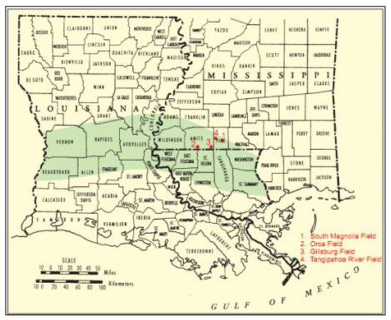
Figure 1.
Regional extent of the Tuscaloosa Marine Shale basin within the eastern Gulf of Mexico margin (adapted from [18]).
John et al. [18] reported that the Tuscaloosa Marine Shale consists of shales with interbedded siltstones, while the lower Tuscaloosa Unit consists of fluvial and deltaic sandstone, siltstone and shales. The Lower Tuscaloosa, consisting of massive sands, represents the first transgressive phase; the middle Tuscaloosa Marine Shale, and a portion of the underneath sandstone, characterize the back-stepping phase of a transgressive–progressive cycle; and the Upper Tuscaloosa Unit, which consists mostly of massive sandstones interbedded with clays and fossil fragments, represent the final regressive phase [1].
3.1.2. Mineralogy Characterization
The mineralogy in the Tuscaloosa Marine Shale (TMS) is highly dominated by clay, phyllosilicate mineral, quartz and calcite. The formation is reported to be highly heterogeneous in terms of mineralogy as a function of depth. The Tuscaloosa Marine Shale (TMS) is characterized by its high concentration in clays. A Fourier-transform infrared spectroscopy (FTIR) analysis revealed a clay content as high as 51% in the TMS. The most common clay types include kaolinite, illite and chlorite. Unlike kaolinite and chlorite, illite and smectite clays are highly detrimental to TMS drilling due to their sensitivity to water. TMS formation is highly heterogeneous, which is reflected by the variation in mineralogy across the formation and at different depths, as reported by Borrok et al. [19]. Their study of mineralogy heterogeneity in Tuscaloosa Marine Shale reported that the concentration of most mineral tends to variate from the base TMS to a higher elevation. Their study revealed that the transition from the lower Tuscaloosa to the TMS is defined by a decrease in quartz content, an increase in calcite and finally a slight increase in total clay content. Their study showed an average clay content of more than 40 wt% from all the wells analyzed and the most dominant clays consisted of illite, kaolinite, chlorite and smectite. These different concentrations were confirmed by the FTIR analysis in this study. Figure 2 shows the FTIR analysis of a TMS core sample.
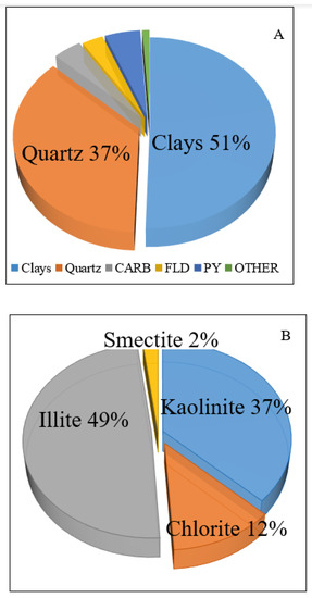
Figure 2.
Mineralogy composition of the Tuscaloosa Marine Shale (TMS) obtained using FTIR analysis: (A) represents the main mineralogy of the TMS and (B) represents the dominant clay minerals in the formation.
Clays, such as illite and smectite, can be very detrimental to the TMS drilling operation if the appropriate drilling fluid system is not selected.
3.2. Eagle Ford Shale
3.2.1. Geological Setting
The Eagle Ford Formation is in an Upper cretaceous organic-rich and calcareous-rich shale that extends through the northeast–southwest band across south Texas. Figure 3 shows the regional extent of the Eagle Ford. The Eagle Ford is characterized by a mixed siliciclastic/carbonate depositional environment across the late cretaceous platform of the Gulf of Mexico. Condon and Dyman [20] reported the Eagle Ford Shale play is stratigraphically variable in terms of thickness, organic content and composition. The Eagle Ford Shale play was deposited during a transgressive cycle in the southern margin of North America, trending from the southwest to the northeast [21]. It is bounded unconformably by the overlying Austin Chalk and the underlying early Cenomanian Buda Formation [22]. Dawson and Almon [23] reported on the major mudstones in Eagle Ford.
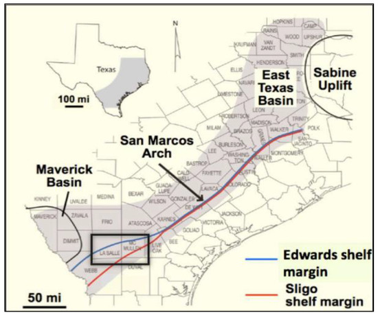
Figure 3.
Regional extent of the Eagle Ford Shale in Texas (modified from Hentz and Ruppel [24]).
3.2.2. Mineralogy Characterization
The mineralogy of the Eagle Ford Shale is highly dominated by calcite, quartz and clay. They make up more than 90% of the mineralogy concentration. Like the Tuscaloosa Marine Shale (TMS), the Eagle Ford formation mineralogy is highly heterogeneous across the formation. Mullen et al. [25] reported that the mineral composition varies as we move across the play. His study revealed that the western wells are more quartz dominant while the wells in other sections are more clay dominant. Unlike in the TMS where the clay concentration exceeds 40 wt%, the clay concentration of the wells analyzed in the Eagle Ford was around 20 wt%. Figure 4 shows the mineralogy composition in the Eagle Ford. Similarly, to the TMS, the Eagle Ford is dominated by clays such as illite. These clays can be very detrimental and should be accounted for when planning for shale drilling.
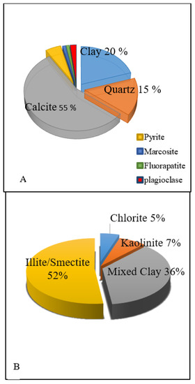
Figure 4.
Mineralogy composition of the Eagle Ford Shale using FITR analysis: (A) represents the main mineralogy of the Eagle Ford and (B) represents the dominant clay minerals.
4. Materials and Methods
4.1. Materials
4.1.1. Core Samples
In this study, vertical cylindrical core samples were prepared to be used for the drilling operations. The core samples were prepared using a coring machine with a bit of 1.5 inch inner diameter. The core samples used for the TMS drilling were obtained from large size cores from wells drilled in the formation, while the Eagle Ford core samples were prepared from outcrops. All core samples used in this study had a cylindrical shape with a diameter of 1.5 inches and height of 1.1 inches. The vertical core samples were used to replicate the vertical wellbore in the actual drilling operations. The core samples were prepared for both formations (Eagle Ford (Texas, Wilson), TMS (Louisiana, East Feliciana)) and were properly drilled. After drilling of the core samples, the drilling parameters were recorded and analyzed for optimization purposes.
4.1.2. Drilling Fluid Systems
This study focuses on evaluating the performance of inhibitive drilling fluid systems. In this study, four sets of drilling fluid systems were obtained. A conventional water-based mud (WBM) systems was prepared to be used as the reference mud due to its high degree of incompatibility with shale drilling, and three sets of inhibitive mud systems (1 wt% KCl, 2 wt% KCl and cesium formate brine). The drilling fluid systems used in this study were obtained in two ways. The conventional water-based mud (WBM) and the KCl mud systems were designed in the laboratory, while the cesium formate brine was obtained from a service company. The drilling fluid systems designed in the laboratory contained materials such as bentonite (gel), lignite, etc. The concentrations of the materials are based on three laboratory barrels. The formulation for the conventional WBM is reported in Table 1. The drilling fluid systems were analyzed, and the rheological properties were obtained.

Table 1.
Conventional water-based mud (WBM) formulation.
4.1.3. Water
Deionized water was used to mix and prepare the drilling fluid systems to be used in the study. For the WBM, the water was directly mixed with the other components, as for the KCl mud systems, the water was solely used to prepare to KCl solution that was mixed with the other components. The water requirement in both cases was determined based on the number of laboratory barrels of the drilling fluid system to be designed.
4.1.4. Other Drilling Fluid Components
In addition to the water, the other components, namely bentonite, lignite, desco, caustic acid and barite, were all used in the designing process of the drilling fluid mud systems. The requirement for these components was defined by the number of laboratory barrels of the drilling fluid system to be designed. All these components play a different role in the designing process of the drilling fluid systems.
4.2. Drilling Fluid Preparation
The drilling fluid systems were mixed according to a practical procedure. The order of the mixing was as follows: water or KCl solution, bentonite, caustic, lignite, desco and barite. The different components were mixed using a laboratory mud mixer. In this study, three laboratory barrels of each mud systems (WBM, KCl muds) were designed.
Two concentrations of KCl solution (1 wt% KCl and 2 wt% KCl,) were designed. The formulation procedure for these two KCl-based systems was similar to that of the conventional WBM. The main difference was replacing the deionized water in a conventional WBM with the KCl solution. The same concentration of gel, caustic, lignite and barite was used for all two KCl mud systems.
4.3. Experimental Procedure
4.3.1. Drilling Fluid Rheology
Drilling fluid rheology is an important parameter for characterizing all fluid systems. The rheological properties can provide insight into the drilling fluid performance in term of fluid loss, filtration and solid and cutting transport ability. The drilling fluid systems were designed by appropriately mixing the required components, namely, the water, bentonite, barite, lignite and others. After mixing, the rheological model investigation was carried out in accordance with the API practice (API 13 B-1 2003) using an M3600 automated viscometer. The viscometer is programmed to profile the drilling fluid rheology parameters, including shear stress, shear rate and apparent viscosity every 30 s at a set temperature. In this study, the temperature was set to 120 °F, while the automatic viscometer has a maximum operating temperature of 220 °F. The rheological investigation was performed for the inhibitive mud systems (1 wt% KCl, 2 wt% KCl and cesium formate) and the conventional WBM. The automated viscometer is connected to a data acquisition system (DAQ) that gets a digital reading that is stored in a computer.
4.3.2. Laboratory Swelling Test
The swelling of clay during drilling is a major source of concern for shale drilling operators because of the potential setbacks that can be associated with it. The swelling test was carried out to investigate the impact of the inhibitive drilling fluid systems on shale swelling. The test was performed on the set of inhibitive mud systems (1 wt% KCl, 2 wt% KCl, cesium formate), conventional WBM and freshwater, which was used as the reference fluid. Various testing procedures are available for quantifying the swelling index; however, the most commonly used one is the linear swell tester. This testing relies on a dynamic swell meter to simultaneously test different fluid systems for extended periods of time at various temperatures up to 180 °F. In this study, a simpler testing procedure that relies on a graduated cylinder was used due to the lack of a dynamic swell meter. This testing procedure is very common for testing bentonite and soil swelling. To perform these tests, a 2 g sample of dried and finely ground shale from both Eagle Ford and TMS were dispersed into a 100 mL graduated cylinder containing the tested drilling fluids in 0.1 g increments. A minimum of 10 min must pass between additions to allow for full hydration and settlement of the clay to the bottom of the cylinder. These steps are followed until the entire 2 g sample had been added to the cylinder. The sample is then covered and protected from disturbances for a period of 16–24 h, at which time the level of the settled and swollen clay is recorded to the nearest 0.5 mL.
4.3.3. Drilling Simulation
In this study, a high-pressure, high-temperature (HPHT) drilling simulator was used to conduct the required experiments to investigate the effectiveness of the inhibitive drilling fluid systems in drilling clay-dominated shale formations. The innovative drilling simulator provides a great opportunity to simulate the typical downhole drilling conditions. A data acquisition system (DAQ) is attached to the drilling simulator to effectively collect the real-time drilling parameters, such as weight on bit (WOB), rate of penetration (ROP), torque and friction factor. The drilling simulator is set to sustain pressures and temperatures up to 2000 psi and 500 °F, respectively. The drilling simulator is equipped with a core holder to effectively hold the core samples to be drilled. The cylindrical core samples obtained from both Eagle Ford and TMS were effectively drilled and the drilling parameters were recorded and analyzed. A total of 350 mL of the drilling fluid systems was measured out and poured into a cell attached to the core holder. The drilling tests were conducted at a temperature of 120 °F, a rotary speed of 75 rpm and differential pressure of 100 psi. The rotary speed used in this study was in accordance with the field drilling report. Each of these parameters can be adjusted to match the downhole conditions required during an actual operation. A 1-inch PDC drill bit was used to drill to the cylindrical cores prepared. The simulator was also equipped with a heating jacket that heats up the system to the required temperature. A normal loading system was used to provide the support force, which is correlated to the weight on bit (WOB). Figure 5 shows a schematic of the drilling simulator used in this study, while Figure 6 shows the real system used to perform the experiments.
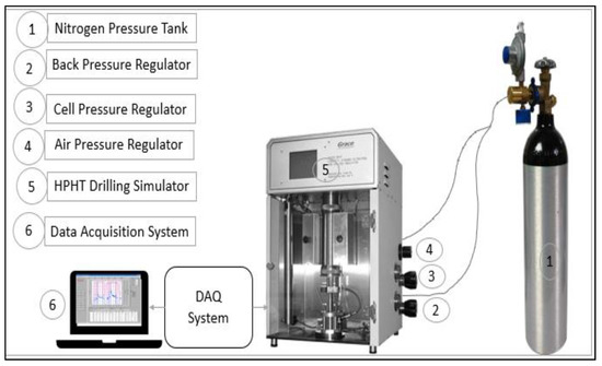
Figure 5.
A schematic of the drilling simulation setup used in this study.
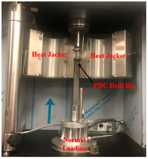
Figure 6.
Actual drilling simulator with the different components used for this study.
5. Results and Discussions
5.1. Drilling Fluid Characterization
The drilling fluid is a major component of all drilling operations. The importance of selecting the appropriate drilling fluid systems is much more crucial when dealing with clay-dominated shale formations such as TMS and Eagle Ford due to incompatibility issues between the fluid and the formation. The rheological profiles for the conventional WBM, 1 wt% and 2 wt% KCl, and the cesium formate are shown in Figure 7 and Figure 8. Figure 7 shows the shear stress vs. shear rate plot of the tested drilling fluid systems at a temperature of 120 °F. All the plots were fitted with a power law equation where the consistency indices and flow behavior indices were reported. The rheological profile reveals an increase in shear stress for the same shear rate from cesium formate to 2 wt% KCl to 1 wt% KCl and to WBM. All plots show a shear thinning process as the shear stress increases as the shear rate increases. A decrease of more than 60% is realized in the shear stress when the inhibitive drilling fluid systems (1 wt% and 2 wt% KCl and cesium formate) are used instead of the conventional WBM. The drilling fluid rheological properties, such as shear stress, can give an indication of the drilling fluid’s ability to control cutting erosion and integrity during drilling. Another important rheological property of the drilling fluid that affect its performance is the apparent viscosity. The apparent viscosity characterized the viscosity at a given shear rate. Figure 8 shows the apparent viscosity profile for the drilling fluid systems tested in this study. The plots show a decreasing correlation between the apparent viscosity and the shear rate. The decrease in the apparent viscosity can be explained by the molecule tendency of aligning with each other at a high shear rate to allow easier flow. The conventional WBM displays higher apparent viscosity, more than 50% compared to the inhibitive mud systems (1 wt% and 2 wt% KCl and cesium formate). The low apparent viscosity realized with the inhibitive mud systems indicated easier flow compared to the conventional WBM. The apparent viscosity also relates to the fluid’s ability to effectively remove solids during drilling. In their study, Saasen et al. [26] showed that there is a strong correlation between the apparent viscosity and the total suspended solids (TSS) content. Their study implied that the apparent viscosity increases if the solid content increases. The apparent viscosity is an important parameter for quantifying a drilling fluid’s ability to suspend solids and the cutting’s retention. There exist different additives, such as nanomaterials, to help the altered drilling fluid viscosity favorably for downhole conditions. The low shear stress at the same shear rate observed with the inhibitive drilling fluid systems can also be explained by the low clay–water interaction, which suppresses the development of viscosity.
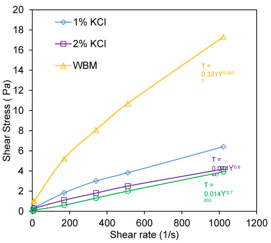
Figure 7.
The shear stress vs. shear rate profiles at 120 °F of the drilling fluid systems tested in this study.
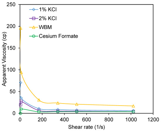
Figure 8.
Apparent viscosity profile at 120 °F of the drilling fluid systems tested in this study.
5.2. Linear Swelling Characterization
Shale swelling is an important parameter to evaluate when characterizing the shale–fluid interaction. The linear swelling is used to quantify the linear expansion of clay when exposed to drilling fluid systems. Shale swelling is very common in clay-dominated formations, such TMS and Eagle Ford. Shale swelling is very detrimental for drilling operations due all the concerns it engenders. The level of swelling is both influenced by the shale formation and the drilling fluid system. The swelling index shows the effect of different drilling fluid systems on clay expansion during the drilling operations. In this study, the swelling index was computed based on the change in volume after a certain period of time. It was obtained from the equation below.
where represents the initial volume of the mixture, the final volume of the mixture (24 h) and the swelling index.
The swelling index was obtained for the four drilling fluid systems tested in this study for TMS and Eagle Foard shale, while using freshwater as the reference fluid. Figure 9 displays the different swelling indices obtained. The profile revealed that freshwater displayed the highest swelling index in both formations (TMS and Eagle Ford) while cesium formate showed the lowest. Freshwater showed a higher swelling index due to the presence of the water-sensitive clay (illite, kaolinite and smectite) in the formation. Among the drilling fluid, the conventional WBM showed the highest swelling index followed by the 1 wt% KCl, the 2 wt% KCL and then the cesium formate. The same trend was observed in both formations. A comparative approach of swelling in both formations showed that the Tuscaloosa Marine Shale (TMS) displayed a higher swelling for all fluid systems tested. This shows that the TMS could have a higher water-sensitive clay compared to the Eagle Ford. Analysis of the mineralogy in both formations confirmed a higher concentration of expandable clays such as smectite in TMS as opposed to Eagle Ford. This indicates that the use of inhibitive mud systems should be more critical in TMS as compared to Eagle Ford.
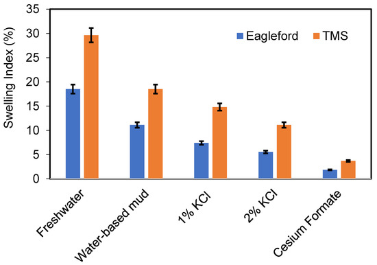
Figure 9.
Swelling index profile of the drilling fluid systems tested in this study, with freshwater as the reference fluid.
In both formations, the study revealed the impact of the inhibitive mud systems in minimizing the swelling during drilling, thus providing better drilling performance by minimizing the drilling concerns, such as a stuck pipe, borehole collapse, etc., and reducing the non-drilling time (NDT). The effectiveness of inhibitive fluid systems, such as cesium formate and the KCl-based fluid systems, in controlling clay swelling has been previously explained by authors such as Van Oort [7], John Downs [11] and Siv Howard [12]. The low swelling rate observed with the cesium formate and KCl-based fluid systems can be explained by the presence of the Cs+ and K+ ions, respectively, since these ions tend to have the ability to lower the hydration tendency of reactive clays such as smectite compared to other bivalent ions. The small size of the potassium ions (K+) increase the inhibitive ability of the KCl-based fluid systems as they can easily fit into the montmorillonite structure to limit hydration [27,28,29]. Similarly, the cesium ion (Cs+), which has an even smaller size than the K+ ion, explains the improved swelling inhibition associated with cesium formate.
5.3. Drilling Parameters
In order to effectively evaluate the performance of the drilling fluid systems, it is crucial to analyze their impact on drilling parameters such as torque, friction factor, rate of penetration (ROP) and the mechanical specific energy (MSE).
5.3.1. Torque and Friction Factor during Drilling
The excessive torque and friction factor during drilling constitute a major concern for all the drilling operators. The excessive torque and friction factor during drilling could be an indication of possible pipe sticking, which is one cause of wellbore instability. High torque and drag forces, as well as the friction factor, constitute major limitations in extended reach, direction wells and deep wells as they prevent operators from reaching the target or increase the total drilling time. Drilling performance can be improved by minimizing both the torque and friction factor during drilling. In this study, the effect of inhibitive mud systems on the torque and friction factor during drilling was evaluated for both formations (TMS and Eagle Ford). Figure 10 and Figure 11 show the torque and friction factor profiles, respectively. The profiles revealed an increasing relationship between both the torque and the friction factor and the weight on bit (WOB). Among the drilling fluid systems tested, the conventional WBM showed the highest torque and friction factor while the cesium formate showed the minimum. The inhibitive mud systems showed a reduction of more than 50%. This indicates that all three inhibitive mud systems tested in this study provide a better drilling performance as opposed to the conventional WBM. The comparative analysis of the performance of all four drilling fluid systems was performed on samples from the Tuscaloosa Marine Shale (TMS). After the best two inhibitive drilling fluid systems were used to drill the samples obtained from the Eagle Ford Shale formation, they were compared to the results obtained from the TMS. Figure 12 shows the effect of the drilling fluid systems on the torque and friction factor in both formations. The study revealed that a lower torque and friction factor was realized in the Eagle Ford formation as opposed to the Tuscaloosa Marine Shale. A reduction of more than 60% was realized when the drilling samples were obtained from Eagle Ford. The low torque and friction factor realized with Eagle Ford Shale indicates better drilling performance at Eagle Ford compared to TMS. Under similar drilling conditions, drilling in Eagle Ford will be more effective than in TMS. The low torque and friction factor obtained with the inhibitive mud systems indicate the positive impact these fluid systems have on drilling in these formations. This emphasizes that the use of inhibitive mud systems is more crucial at TMS than at Eagle Ford to optimize the drilling practices in the aforementioned formation. Previous studies showed the effectiveness of the formate brine, such as cesium formate, in drilling the HPHT shale formations. These fluid systems help reduce torque and drag during shale drilling operations and improve drilling operations [11,12,30].
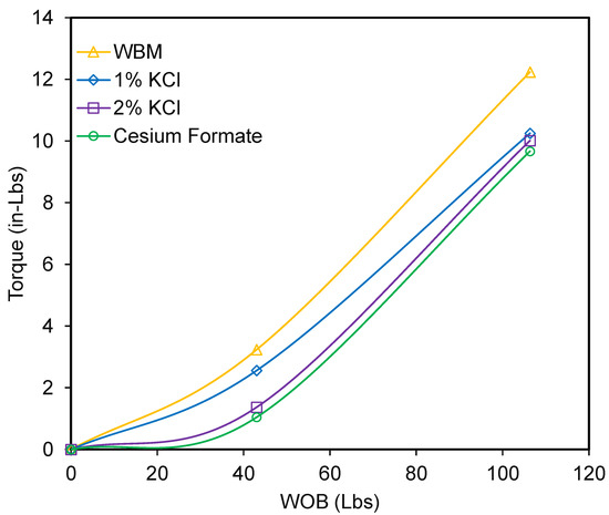
Figure 10.
Effect of the tested drilling fluid systems on torque during drilling.
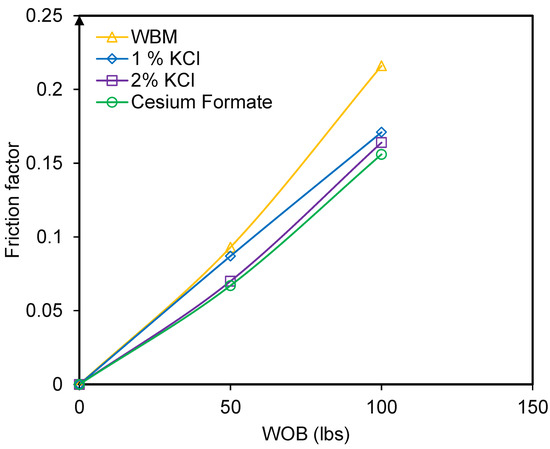
Figure 11.
Effect of the tested drilling fluid systems on the friction factor during drilling.
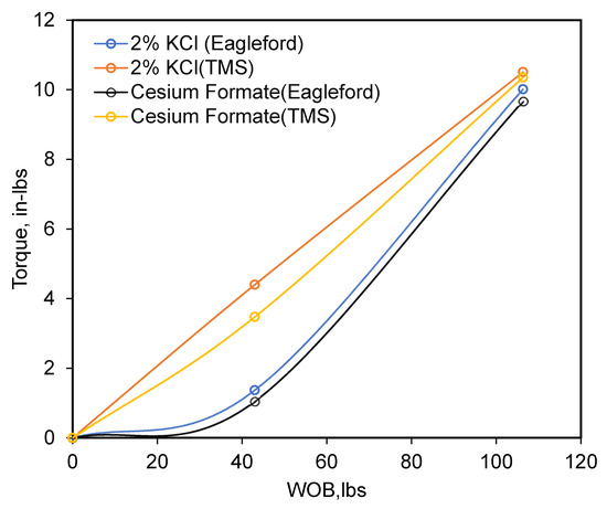
Figure 12.
Effect of the two inhibitive mud systems (2 wt% KCl and cesium formate) on torque in TMS and Eagle Ford.
5.3.2. ROP Optimization
The rate of penetration (ROP) constitutes one of the most important parameters to evaluate when analyzing drilling performance. The ROP refers to how fast we can drill. Most shale formations, such as TMS and Eagle Ford, are characterized by a low drilling rate. This issue is mostly due to factors such as bit-balling and pipe hole sloughing that are caused by the incompatibility between the fluid system and the formation. In this study, the effect of inhibitive mud systems (1 wt% and 2 wt% KCl and cesium formate) and the conventional WBM on the drilling rate was evaluated. The rate of penetration is characterized as a dependent parameter that can be predicted using independent parameters, such as weight on bit (WOB) and rotary speed. The drilling conditions were consistent and all the same for the drilling tests in order to fully evaluate the effect of the drilling fluid systems. The effect of the fluid systems tested was evaluated in both TMS and Eagle Ford. Figure 13 shows the ROP profile of the drilling fluid systems tested on TMS core samples. The results show an increasing correlation between the ROP and the WOB for all drilling fluid systems. Based on the ROP profile, conventional WBM showed the lowest ROP at various weights on bit (WOB) among the drilling fluid systems tested. This result was an indication of the incompatibility issues associated with WBM. Among the inhibitive mud systems tested, the cesium formate showed the highest rates followed by the 2 wt% KCl, and finally the 1 wt% KCl. This analysis indicates that cesium formate would perform better and be the most appropriate drilling fluid systems for reactive shale formations. However, due to the high cost of cesium formate and the closeness in drilling performance between the cesium formate and the 2 wt% KCl fluid system, the use of KCl fluid systems will be more suitable as it will be cost effective and simultaneously solve the major concern of a low drilling rate in reactive shales. The two best inhibitive mud systems (cesium formate and 2 wt% KCl) were tested on core samples obtained from Eagle Ford. Only two fluid systems were tested due to the limitation on the number of core samples from Eagle Ford. A comparative analysis of drilling fluid performance in both formations was performed in this study. Figure 14 shows the ROP profile in Eagle Ford Shale and TMS. The profile shows that both inhibitive mud systems (cesium formate and 2 wt% KCl) performed better in Eagle Ford Shale as compared to the TMS. These results were also supported by the swelling indices obtained in both formations for the tested drilling fluid systems.
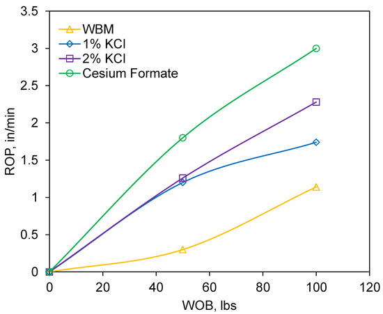
Figure 13.
Rate of penetration profile for the drilling fluid systems tested on TMS core samples.
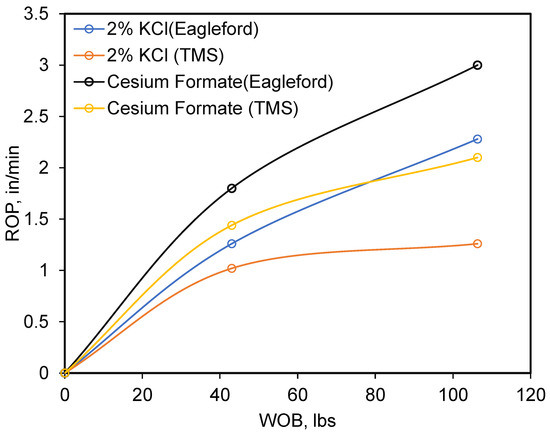
Figure 14.
The rate of penetration (ROP) profile of cesium formate and 2 wt% KCl in Eagle Ford and TMS.
5.3.3. Mechanical Specific Energy (MSE) Optimization
Another major parameter for measuring drilling efficiency is the mechanical specific energy (MSE). The MSE is defined as the amount of energy required for removing a unit of volume rock. The MSE is highly dependent on factors such as torque, weight on bit (WOB), rate of penetration (ROP) and rotary speed (RPM). Pessier et al. [30] reported that drilling efficiency can be improved by optimizing the controllable factors that will eventually lead to a minimum MSE. In this study, the MSE was computed using the controllable factors, including torque, rate of penetration, rotary speed and WOB obtained during drilling operations. The calculation of the MSE was done using the equation below. The MSE can be impacted by the mechanical efficiency during drilling. The mechanical efficiency is dependent on the bit type, the formation and well trajectory. Amadi et al. [31] reported that the mechanical efficiency for directional and horizontal drilling is assumed to be 12.5%.
The effect of the four drilling fluid systems (the conventional WBM and three inhibitive mud systems) was first evaluated using the TMS core samples and the two best drilling fluid systems were used to drill the Eagle Ford samples for a comparative analysis with the TMS formation. Figure 15 shows the MSE profile at various WOB for the tested drilling fluid systems in TMS. The profile revealed that the highest MSE was realized with the conventional WBM, followed by the 1 wt% KCl, then the 2 wt% KCl, and finally the cesium formate. The MSE realized with conventional WBM was 80% higher than that of the inhibitive mud systems (1 wt%, 2 wt% KCl and cesium formate). The drilling efficiency is indirectly proportional to the MSE. This implies that the inhibitive mud systems will be more efficient at drilling clay-concentrated shale formations than the WBM; this supports the incompatibility between the conventional WBM and most shale formations. Among the inhibitive mud systems, the cesium formate provided the highest performance as it required less energy to drill a volume of rock.
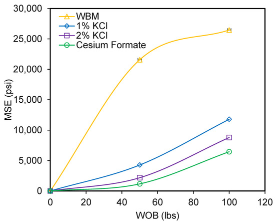
Figure 15.
The mechanical specific energy profile for the tested drilling fluid systems in the TMS.
The two best drilling fluid systems were selected and their effect on MSE in both TMS and Eagle Ford Shale was evaluated. Figure 16 shows the MSE profile of the tested drilling fluid in both formations. The result shows that the minimum MSE was realized in the Eagle Ford formation for both fluid systems. A more than 60% reduction in MSE was realized when drilling an Eagle Ford core sample in place of TMS. The minimum MSE obtained with the Eagle Ford formation correlates to the low torque in the formation. Since a high torque is required for drilling stronger rock, the low torque in the Eagle Ford formation indicates a lower rock strength compared to TMS. The high quartz content, which is more than twice that of the Eagle Ford formation, is an indication of the high rock strength in the TMS. The low MSE obtained in the Eagle Ford formation can be attributed to the improved drilling performance and the weak rock strength in the formation. Under similar drilling conditions, the use of inhibitive mud systems (KCl and cesium formate) will be more effective in Eagle Ford, as shown in the MSE and the rate of penetration (ROP) profile for both formations. The MSE results also indicate a higher rock strength in the TMS as opposed to Eagle Ford.
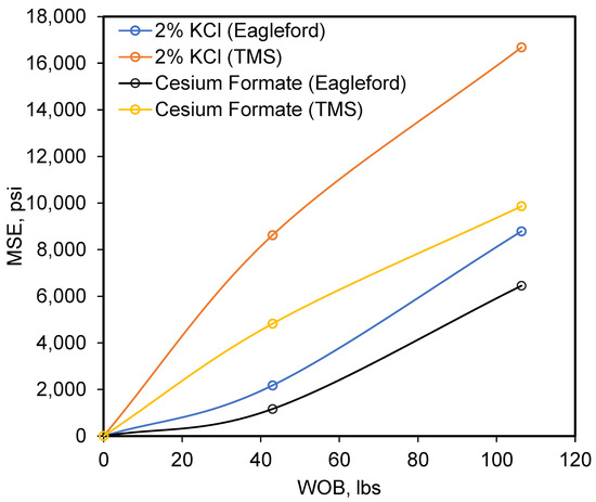
Figure 16.
The mechanical specific energy (MSE) profile for cesium formate and 2 wt% KCl in TMS and Eagle Ford.
6. Conclusions
The study presents the inhibitive drilling fluid systems’ performance in clay-dominated shale formations of Eagle Ford and Tuscaloosa Marine Shale (TMS). The performance of the fluid systems was analyzed by evaluating their impact on the drilling parameters, including the torque and friction factor, rate of penetration (ROP) and mechanical specific energy (MSE). The drilling fluid systems tested included the conventional WBM and three sets of inhibitive mud systems (1 wt% and 2% KCl and cesium formate). The following conclusions were drawn from the experimental investigation.
- The cesium formate showed the lowest swelling index among the tested drilling fluid systems with an index of about 4% followed by the 2% KCl systems.
- The Eagle Ford Shale formation registered the lowest swelling index for all drilling fluid systems when compared to TMS. This was supported by the presence of a high concentration of swelling clays in TMS.
- A very low friction factor and torque was reported during drilling when using inhibitive mud (cesium formate and KCl mud systems). The inhibitive mud systems showed a higher drilling performance as compared to the conventional WBM systems.
- The minimum friction factor and torque were realized in Eagle Ford as compared to TMS, indicating a higher drilling performance in Eagle Ford.
- The highest rate of penetration during drilling was realized with cesium formate, followed by the 2 wt% KCl mud, while the lowest was associated with the conventional WBM. No major difference in ROP was realized between the cesium formate and the KCl systems. The KCl mud systems can be an alternative to cesium formate to save cost.
- A minimum mechanical specific energy was realized with the cesium formate and the 2 wt% KCl mud system, while the conventional WBM showed the maximum MSE, which was 80% higher than that of the inhibitive mud systems (1 wt% and 2 wt% KCl and cesium formate).
- The MSE is highly dependent on the drill bit selected and the bit efficiency. The normalized MSE by the bit mechanical efficiency minimizes the effect of the bit.
- A higher rate of penetration (ROP) and lower mechanical specific energy (MSE) were obtained in the Eagle Ford formation as opposed to TMS. This confirmed that the drilling using inhibitive mud systems could be more effective in Eagle Ford than TMS.
Author Contributions
Conceptualization, N.K. and S.S.; methodology, N.K.; writing—original draft preparation, N.K.; writing—review and editing, S.S.; supervision, S.S.; project administration, S.S.; funding acquisition, S.S. All authors have read and agreed to the published version of the manuscript.
Funding
This research was partially funded by the Department of Energy National Energy Technology Laboratory under Award Number DE-FE0031575 (TUSCALOOSA MARINE SHALE LABORATORY).
Acknowledgments
The authors would like to extend their gratitude to all the service companies that provided the materials needed for this study. The authors would also like to thank Jeff McCaskill of the Well Construction and Technology Center, the University of Oklahoma. Their gratitude also goes to Stuart Leon of Cabot Corporation. This material is based upon work partially supported by the Department of Energy National Energy Technology Laboratory under Award Number DE-FE0031575 (TUSCALOOSA MARINE SHALE LABORATORY).
Conflicts of Interest
The authors declare no conflict of interest.
Nomenclature
| Acronyms | |
| AB | Cross-Sectional Area |
| DAQ | Data Acquisition System |
| Ef | Mechanical Efficiency |
| HPHT | High-Pressure High-Temperature |
| Lb/bbl | Pounds per Barrel |
| MSE | Mechanical Specific Energy |
| NDT | Non-Drilling Time |
| NPT | Non-Productive Time |
| OBM | Oil-Based Mud |
| ROP | Rate of Penetration |
| RPM | Rotary Speed |
| T | Torque |
| TMS | Tuscaloosa Marine Shale |
| WBM | Water-Based Mud |
| WOB | Weight on Bit |
| Greeks | |
| σ | Swelling Index (Equation (2)) |
References
- O’Brien, D.E.; Chenevert, M.E. Stabilizing sensitive shales with inhibited, potassium-based drilling fluids. J. Pet. Technol. 1973, 25, 1089–1100. [Google Scholar] [CrossRef]
- Awal, M.R.; Khan, M.S.; Mohiuddin, M.A.; Abdulraheem, A.; Azeemuddin, M. A new approach to borehole trajectory optimisation for increased hole stability. In SPE Middle East Oil Show; Society of Petroleum Engineers: Dallas, TX, USA, 2001. [Google Scholar]
- Pašić, B.; Gaurina Međimurec, N.; Matanović, D. Wellbore instability: Causes and consequences. Rudarsko-geološko-naftni zbornik 2007, 19, 87–98. [Google Scholar]
- Santarelli, F.J.; Chenevert, M.E.; Osisanya, S.O. On the Stability of Shales and Its Consequences in Terms of Swelling and Wellbore Stability. In Proceedings of the SPE/IADC drilling Conference, Louisiana, NO, USA, 18–21 February 1992. SPE-23886-MS. [Google Scholar] [CrossRef]
- Mohiuddin, M.A.; Awal, M.R.; Abdulraheem, A.; Khan, K. A New Diagnostic Approach to Identify the Causes of Borehole Instability Problems in an Offshore Arabian Field; Society of Petroleum Engineers: Dallas, TX, USA, 2001. [Google Scholar] [CrossRef]
- Mody, F.K.; Hale, A. Borehole-stability model to couple the mechanics and chemistry of drilling-fluid/shale interactions. J. Pet. Technol. 1993, 45, 1093–1101. [Google Scholar] [CrossRef]
- Van Oort, E. Physio-Chemical Stabilization of Shales. SPE Oilfield Chem; International Symposium: Houston, TX, USA, 1997; SPE-37263-MS. [Google Scholar] [CrossRef]
- Paiaman, A.M.; Al-Askari MK, G.; Salmani, B.; AlAnazi, B.D.; Masihi, M. Effect of Drilling Fluid Properties on Rate of Penetration. NAFTA 2009, 60, 129–134. [Google Scholar]
- Bourgoyne, A.T.; Young, F.S., Jr.; Millheim, K.K.; Chenevert, M.E. Applied Drilling Engineering SPE Textbook Series; Society of Petroleum Engineers: Richardson, TX, USA, 2003; Volume 2. [Google Scholar]
- Konate, N.; Ezeakacha, C.P.; Salehi, S.; Mokhtari, M. Application of an Innovative Drilling Simulator Set Up to Test Inhibitive Mud Systems for Drilling Shales. In Proceedings of the SPE Oklahoma City Oil and Gas Symposium, Oklahoma City, OK, USA, 9–10 April 2019. SPE-195189-MS. [Google Scholar] [CrossRef]
- Downs, J.D. Formate Brines: Novel Drilling and Completion Fluids for Demanding Environments; Society of Petroleum Engineers: Dallas, TX, USA, 1993. [Google Scholar] [CrossRef]
- Howard, S.K. Formate Brines for Drilling and Completion: State of the Art; Society of Petroleum Engineers: Dallas, TX, USA, 1995. [Google Scholar] [CrossRef]
- Mancini, E.A.; Puckett, T.M. Transgressive-Regressive Cycles: Application to Petroleum Exploration for Hydrocarbons Associated with Cretaceous Shelf Carbonates and Coastal and Fluvial-Deltaic Siliciclastics; SEPM Foundation: Northeastern Gulf of Mexico, Mexico, 2002; pp. 173–199. [Google Scholar]
- Pair, J.D. The Tuscaloosa Marine Shale: Geological History, Depositional Analysis, and Exploration Potential. Bachelor of Science Thesis. Electronic Theses and Dissertations. 68. 2017. Available online: https://scholarworks.sfasu.edu/etds/68 (accessed on 29 September 2020).
- Dubiel, R.F.; Pitman, J.K. Extended Abstract: Analysis of the Tuscaloosa-Woodbine total petroleum system and implications for assessing conventional gas resources in the downdip trend. GCAGS Trans. 2004, 54, 54–56. [Google Scholar]
- Lowery, C.M.; Cunningham, R.; Barrie, C.D.; Bralower, T.; Snedden, J.W. The northern Gulf of Mexico during OAE2 and the relationship between water depth and black shale development. Paleoceanography 2017, 32, 1316–1335. [Google Scholar] [CrossRef]
- John, C.J.; Moncrief, J.E.; Jones, B.L.; Harder, B.J. Regional Extent and Hydrocarbon Potential of the Tuscaloosa Marine Shale, United States Gulf Coast. GCAGS Trans. 1997, 47, 395–402. [Google Scholar]
- Borrok, D.M.; Wan, Y.; Wei, M.; Mokhtari, M. Heterogeneity of the Mineralogy and Organic Content of the Tuscaloosa Marine Shale. Mar. Pet. Geol. 2019, 109, 717–731. [Google Scholar] [CrossRef]
- Condon, S.M.; Dyman, T.S. Geologic Assessment of Undiscovered Conventional Oil and Gas Resources in the Upper Cretaceous Navarro and Taylor Groups; U.S. Geological Survey Digital Data Series DDS–69–H: Western Gulf Province, TX, USA, 2003; Chapter 22006; 42p. [Google Scholar]
- Dawson, W.C. Limestone Microfacies and Sequence Stratigraphy: Eagle Ford Group (Cenomanian-Turonian) North-Central Texas outcrops. GCAGS Trans. 1997, XLVII, 99–106. [Google Scholar]
- Donovan, A.D.; Staerker, T.S. Sequence stratigraphy of the Eagle Ford (Boquillas) Formation in the subsurface of South Texas and outcrops of West Texas. GCAGS Trans. 2010, 60, 861–899. [Google Scholar]
- Dawson, W.C. WR Almon, Eagle Ford Shale Variability: Sedimentologic Influences on Source and Reservoir Character in an Unconventional Resource Unit. GCAGS Trans. 2010, 60, 181–190. [Google Scholar]
- Hentz, T.F. SC Ruppel, Regional Stratigraphic and Rock Characteristics of Eagle Ford Shale in its Play Area: Maverick Basin to East Texas Basin: AAPG Search and Discovery Article 10325. Available online: http://www.searchanddiscovery.com/pdfz/documents/2011/10325hentz/ndx_hentz.pdf.html (accessed on 21 October 2015).
- Mullen, J. Petrophysical Characterization of the Eagle Ford Shale in South Texas. In Proceedings of the Canadian Unconventional Resources and International Petroleum Conference, Calgary, AB, Canada, 19–21 October 2010. [Google Scholar]
- Saasen, A.; Løklingholm, G. The Effect of Drilling Fluid Rheological Properties on Hole Cleaning. In Proceedings of the IADC/SPE Drilling Conference, Dallas, Texas, USA, 26–28 February 2002. [Google Scholar]
- Konate, N.; Magzoub, M.; Salehi, S.; Ghalambor, A.; Mokhtari, M. Evaluation of Mud Systems for Drilling High Clay Shales in Dynamic Conditions: Comparison of Inhibitive Systems. In Proceedings of the SPE International Conference and Exhibition on Formation Damage Control, Lafayette, LA, USA, 19–21 February 2020. [Google Scholar] [CrossRef]
- Van Oort, E.; Ripley, D.; Ward, I. Silicate-based drilling fluids: Competent, cost-effective and benign solutions to wellbore stability problems. In Proceedings of the IADC/SPE Drilling Conference, New Orleans, LA, USA, 12–15 March 1996; pp. 189–203. [Google Scholar]
- Patel, A.; Gomez, S.L. Shale Inhibition: What Works? In Proceedings of the SPE International Symposium on Oilfield Chemistry, The Woodlands, TX, USA, 8–10 April 2013. [Google Scholar] [CrossRef]
- Saasen, A.; Jordal, O.H.; Burkhead, D.; Berg, P.C.; Løklingholm, G.; Pedersen, E.S.; Harris, M.J. Drilling HT/HP Wells Using a Cesium Formate Based Drilling Fluid. In Proceedings of the IADC/SPE Drilling Conference, Dallas, TX, USA, 26–28 February 2002. [Google Scholar] [CrossRef]
- Pessier, R.C.; Fear, M.J. Quantifying Common Drilling Problems with Mechanical Specific Energy and Bit-Specific Coefficient of Sliding Friction. In Proceedings of the SPE Annual Technical Conference and Exhibition, Washington, DC, USA, 4–7 October 1992. [Google Scholar] [CrossRef]
- Amadi, W.K.; Iyalla, I. Application of Mechanical Specific Energy Techniques in Reducing Drilling Cost in Deepwater Development. In Proceedings of the SPE Deepwater Drilling and Completions Conference, Galveston, TX, USA, 20–21 June 2012. [Google Scholar] [CrossRef]


© 2020 by the authors. Licensee MDPI, Basel, Switzerland. This article is an open access article distributed under the terms and conditions of the Creative Commons Attribution (CC BY) license (http://creativecommons.org/licenses/by/4.0/).