Abstract
The use of a direct torque control (DTC) drive is a well-known control strategy that is applied frequently to induction motors. Although torque and stator flux ripples are major disadvantages of this approach, using a higher-level inverter helps to overcome these issues. In this paper, we propose a novel switching table with a modified control strategy for a three-level inverter to achieve ripple minimization, as well as smooth switching and neutral point balance; the latter features are generally ignored in many works. The proposed model is compared with a conventional DTC and an improved three-level inverter-fed voltage vector synthesis model in the Matlab/Simulink® environment with low, normal, and high-speed operation under load torque disturbances. The performance indexes and the comparative results confirm the effectiveness of the proposed model in reducing the torque and stator flux ripples by up to and , respectively, generating a lower total harmonic distortion (THD%) in all scenarios, in addition to maintaining the neutral point balance and preventing voltage jumps across the switches of the inverter.
1. Introduction
The conventional direct torque control (DTC) drive has been investigated and developed as a replacement for field-oriented control (FOC) in high-performance AC motor drives [1]. DTC is well-known for its fast torque response, which requires no coordinate transformation, current control or modulation techniques [2]. Furthermore, the simple architecture and robustness against parameter variations are advantages of this approach [3,4]. The inherent benefits of DTC have made it a popular solution for a wide variety of applications, from brushless DC [5] to permanent magnets [6] and switch reluctance motors [7]. Considering the fact that rotor speed encoders are expensive, can have high maintenance costs and are not suitable for harsh environments, numerous sensorless DTC strategies have been proposed [8,9,10]. Although torque hysteresis controller-based DTC (THC-DTC) is considered to be a fast dynamic response controller, its main drawbacks are high torque ripple and flux droop in the low-speed region [11,12]. Torque ripple has a direct relationship with mechanical loss and tensions on the motor shaft, while flux ripple indicates harmonics and a distorted current waveform.
Researchers have addressed these weaknesses in many works by introducing various strategies; one of these strategies is space vector modulation for classical DTC (DTC-SVM) [13]. However, its reference voltage estimation is a complicated process [14] and advanced control strategies are required to develop precise flux and torque responses. DTC has been studied with other control methods including a sliding mode controller [15,16], dead-beat control [17], artificial neural networks (ANN) [18], predictive torque control [19] and state feedback control [20].
Another technique that is used to enhance the performance of DTC is the duty-ratio control of the injected voltage vectors (DR-DTC). To minimize torque and flux ripples in DR-DTC, adjusting the duty-ratios of voltage vectors is a necessity and requires a variable switching frequency [21,22]. In [23], the duty cycle of the active vector was increased to compensate the sector flux droop by using interleaving carriers, but this strategy resulted in high torque and flux ripples when compared against THC-DTC. Duty cycle-based methods were proposed in [24,25] to improve the low-speed performance of an interior permanent magnet synchronous motor (IPMSM). Although the ripple reduction algorithm works well at low speed, tracking performance degrades at high speed.
Additionally, the constant switching frequency torque controller (CSFTC) has been studied as an alternative. It consists of some triangular carriers and a PI (Proportional-Integral) controller that decreases the variations in the switching frequency to reduce torque ripple.
Some researchers have studied multi-level inverters (MLIs) with DTC for induction motors (IMs) and permanent-magnet synchronous motors (PMSMs) and recommended the three-level neutral-point clamped (3L-NPC) inverter for CSFTC to limit torque and flux ripples. However, these approaches mostly suffer from high complexity and require difficult computations in real industrial applications [26,27].
On the other hand, the three-level inverter can bring many benefits including more voltage vectors with different magnitudes, lower voltage distortion levels, lower stress across the semiconductors, less harmonic content, lower switching frequencies, a reduction of torque and flux ripples and performance improvement under low-speed operations as long as an appropriate switching algorithm is executed [28,29,30,31]. Regarding the industrial applications of MLI-fed DTC, the three-level neutral-point-clamped 3L-NPC inverter is one of the most popular cases that has been considered as a research topic over the past few years [32,33,34].
Accordingly, Tang et al. [35] were able to successfully reduce torque ripple by up to 50% with a specific three-level inverter-fed DTC drive by proposing a switching table. However, they overlooked many voltage vectors and used only six smaller vectors. Although lower voltage levels can reduce the torque ripple, the drive becomes incapable of generating a higher electromagnetic torque when it needs to handle heavier loads at higher speeds.
In [36], an instant switching table for a DTC drive was presented. An optimization algorithm was used, and the whole structure of a DTC drive was changed to create a quasi-optimal switching pattern in each interval. The performance of the proposed approach shows an approximately 50% improvement in some situations; however, the switching frequency in their model goes up to 20 KHz at some points. It requires physical modifications in the existing DTC drive and has a heavy computational burden as it needs to constantly solve an optimization problem at each sampling time.
Eventually, an improved 3L inverter-fed DTC drive was proposed that employed unique vector synthesis sequences to reduce the torque ripple in the motor and provide smooth switching and neutral point balance in the inverter [37,38]; the vector synthesis sequence in [38] is used as a benchmark for this study and is investigated thoroughly in Section 3. This is one of the few studies to address neutral point balance and smooth switching problems alongside ripple reduction concerns.
Neutral point unbalance causes the DC-link voltage to deviate from the reference value, causing voltage ripples, increasing the total harmonic distortion (THD%) in the output current and possibly leading to a fault-trip [39]. In addition, smooth switching secures the safe operation of the inverter by preventing voltage jumps across the semiconductors, which also increases the harmonic contents in the output [38].
The contribution of this study is the creation of an optimized control method for a 3L inverter-fed DTC drive by proposing a novel switching table with a modified control loop. First, the proposed switching table is arranged in such a way that it prevents voltage jumps over the inverter gates and provides neutral point balance. Second, the vectors are generated by the specific gates that require fewer switching occurrences. This can be achieved by retaining the same switching states. Third, the stator flux plane is divided into 12 controlling sectors, which allows a greater controlling resolution and doubles the possible solutions for vector selection. Fourth, the torque and flux hysteresis controllers are replaced with five and three-level controllers, respectively. This modification means that the drive is capable of discriminating between smaller and larger torque errors and simultaneously adds a constant flux region. Thus, the expectation of this study is decreased torque and flux ripples, as well as harmonic components on the input current, keeping the neutral point of the inverter isolated and providing smooth switching. Furthermore, some important notes are provided that will help in the tuning of a DTC drive.
This paper is organized as follows: we introduce the mathematical model of an induction motor in Section 2. The structure of the proposed model is presented in Section 3 along with the structure of a three-level inverter and its optimized switching table. Afterwards, a series of simulations is presented to illustrate the effectiveness of the proposed model in terms of the different factors of torque ripple, flux ripple, flux trajectory and THD% in Section 4. Ultimately, all the accomplishments and the results are summarized and analyzed in Section 5.
2. Induction Motor Equations
In order to estimate the torque and stator flux of an induction motor (IM), the first step is to transform the sampled voltage and currents from the to the frame using Clarke transformation.
where and are the input three-phase voltages in and frames, respectively. Similarly, is obtained from measurements. It should be noted that, since and are all 120 apart, the third row of the Clarke transformation is zero (as long as the load is balanced). Thus, an isolated neutral point exists if .
The stator voltage in an asynchronous motor can be expressed by a voltage drop in the stator winding and the electromotive force generated by the flux, as expressed in Equation (2). Then, in order to estimate the amplitude and phase of the flux, first, the components of the stator flux need to be calculated with Equation (3), which is derived by integrating Equation (2).
where , , and are the stator resistance, the flux components and the stator current, respectively. Equation (4) estimates the stator flux magnitude and its angle, and Equation (5) calculates the electromagnetic torque.
where is the electromagnetic torque and p represents the pole pairs of the stator winding.
3. Three-Level Inverter Fed DTC Strategies
3.1. Proposed DTC Model
Figure 1 depicts a general schematic of a DTC drive. The sampled voltage and current vectors are transformed to the frame using Equation (1), and the main DTC block estimates the torque and stator flux using Equations (4) and (5). A speed controller compares the current rotor speed with the desired value and generates two reference values for torque and flux. Then, two hysteresis controllers produce the required commands for the switching table to satisfy the demanded rotor speed by contrasting the actual and reference values of torque and flux. Thus, the decoupled control of torque and flux can be achieved in DTC. The simplicity and independency of motor parameters are decisive factors in the popularity of DTC.
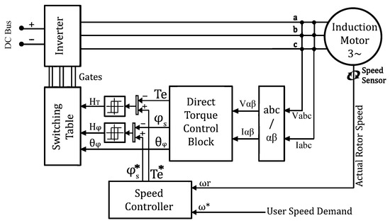
Figure 1.
Block diagram of a conventional direct torque control (DTC) drive.
Likewise, our proposed method does not include any additional motor parameters in the control loop, and it does not affect the system with an extra computational burden. However, it is updated with a 12-sector stator flux plane, higher levels of torque and flux hysteresis controllers, a three-level inverter and an optimized switching table that coordinates and exploits all these advantages. Figure 2 illustrates the structure of an NPC 3L inverter. Figure 3 shows how the 19 unique voltage vectors of the 3L inverter are distributed on the 12 equally divided sectors of the stator flux plane. The proposed method allocates at least one voltage vector to each section to increase control resolution. In contrast to the conventional method, which needs 60 to change the flux hysteresis command, the proposed method selects appropriate vectors every 30. Besides, the 3L inverter provides us with voltage vectors of different sizes (, , and 0), which opens up new possibilities for compensating the torque error. Different states of [2, 1, and zero] mean [full, half, and zero] voltages of the DC link.
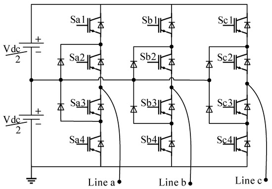
Figure 2.
The structure of a general three-level (3L) inverter.
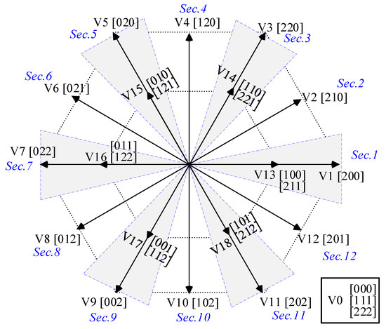
Figure 3.
The proposed stator flux plane and the voltage vectors of a 3L inverter.
The process of generating reference torque and flux signals is similar to the conventional DTC, as demonstrated in Figure 4. A proportional-integral controller (PIC) is responsible for translating the rotor speed error into the required torque to satisfy the speed demand. Several other controllers can be employed for this task; however, for the sake of simplicity and in order to provide a fair comparison between different strategies, the PIC is retained.
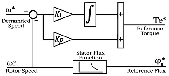
Figure 4.
The structure of a PI speed controller for a DTC drive.
The reference stator flux is kept constant and equal to the nominal flux within the operational speed range (0 to nominal speed). However, at very high speed ranges, flux weakening is required to keep the motor within the constant power region [40]. Thus, when the rotor speed exceeds nominal speed, a flux weakening algorithm reduces the reference flux according to Equation (6).
where and are the reference and nominal stator fluxes, while and are the actual and nominal rotational speeds, respectively.
Figure 5 exhibits five-level torque and three-level flux hysteresis controllers that are replaced with the conventional three-level and two-level torque and flux controllers, respectively. The proposed technique differentiates between small and large torque errors so that it triggers higher voltage levels to compensate larger torque errors and fires smaller vectors for smaller errors. Consequently, the output of the proposed five-level torque hysteresis controller can be :
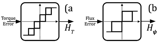
Figure 5.
(a) The proposed five-level torque controller and (b) the three-level flux hysteresis controller.
- Torque error is large and positive
- Torque error is small and positive
- Torque error is acceptable
- Torque error is small and negative
- Torque error is large and negative
According to Figure 3, there are at least two vectors that are perpendicular to each section, which enables us to add the third level for the flux hysteresis controller. Thus, its outputs are defined as
- Flux error is positive
- Flux error is acceptable
- Flux error is negative
It must be taken into consideration that it is not possible to reduce the torque or flux ripples only by tightening the torque or flux hysteresis bands. A very wide band will result in more ripples and even produce insufficient amounts of torque in some instances. Furthermore, tightening the torque or flux hysteresis bands can result in a significant increase in the switching frequency. Mitigating the ripples mostly depends on the sampling time of the control system and the magnitude of the injected voltage vectors. Trying to compensate a small torque error with a large voltage vector will result in an overshoot from the desired limits in a given sampling time; thus, attempting to alter the hysteresis bands is futile. In other words, if the hysteresis bands are set to be too narrow, not only will the ripples not decrease, but also the switching frequency (i.e., switching losses) will increase for no gain. Thus, adjusting the optimized hysteresis bands is of foremost importance, although this fact is unfortunately neglected by many researchers.
Eventually, the conventional switching table will no longer be applicable and a novel switching table will be needed to utilize the expressed model. Considering the 19 unique voltage vectors of the three-level inverter, the 12 flux sectors, the five levels for torque commands and three levels for flux commands, the proposed optimized switching table for a three-level inverter-equipped DTC drive is presented in Table 1. Evidently, the preference is for selecting smaller vectors (), while bigger vectors () are used for the compensation of considerable deviations from the tolerable torque error. It is believed that, in most of the steady-state conditions, half of the DC link voltage is enough to satisfy the user demand. At the same time, the full magnitude vectors are generally needed only during the transient states to provide higher electromagnetic torque.

Table 1.
The proposed switching table for the three-level inverter-fed DTC drive.
It is noteworthy that, according to Figure 3, there are two possible switching patterns for generating vectors to . For the purpose of smooth switching and preventing voltage jumps across the inverter gates, and considering the fact that the proposed model generally injects zero or half of the DC voltage, the 0 and 1 states of the switches are chosen in the switching table. For instance, when there is a change from [100] to , it is better to trigger [110] instead of [221], because transferring from [100] to [110] causes only one half of a DC voltage increase in the second leg of the inverter. On the other hand, transferring from [100] to [221] means a half DC link voltage increase in the first and the third legs, and a full voltage jump in the second leg. The proposed optimized switching table follows this rule in order to prevent voltage jumps and simultaneously to decrease the switching frequency. Besides, the switching pattern is organized in such a way that it maintains the neutral point balance and ensures zero current in the neutral point. According to the above-mentioned considerations, and to are triggered using these states:
- *
- [1 1 1], [1 0 0], [1 1 0], [0 1 0], [0 1 1], [0 0 1], [1 0 1].
where, [1 1 1] acts as an intermediate that prevents voltage jumps between states 0 and 2.
3.2. Voltage Vector Synthesis Strategy
In order to provide a fair comparison with another DTC technique that utilizes a 3L inverter, a vector synthesis method was chosen [38]. As discussed in the first section, this is one of the best-known strategies, especially for 3L inverter-fed DTC drives. This method utilizes all the voltage vectors of a 3L inverter and produces the desired synthesized vectors at different angles. This method secures smooth switching, maintains neutral point balance and has been proposed for ripple reduction purposes. Figure 6 illustrates the synthesized voltage vectors that are produced with the vector synthesis sequence presented in Table 2. The design and implementation details of the vector synthesis strategy are laid out in [38].
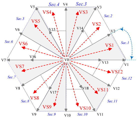
Figure 6.
Synthesis vector diagram [38].
Table 2.
Switching sequences used to generate synthesized voltage vectors [38].
As stated in Table 2, in every transition, only one state changes. In order to prevent voltage jumps, every sequence begins with . To synthesize each vector, eight voltage vectors are triggered with equal duty ratios. Thus, the eight sampling times last until a vector is synthesized. Unlike the conventional DTC methods, the switching frequency is constant for this technique and is determined by the duty ratio of each vector. This model is equipped with two three-level hysteresis controllers to define both torque and flux commands. The switching table is provided in Table 3, where k is the number of the estimated flux sector. It is worthy of mention that this model requires a smaller sampling time for the switching circuit and an up to three times higher switching frequency [38].
Table 3.
Switching table of vector synthesis DTC [38].
4. Simulation Results and Discussion
A series of comprehensive simulations were carried out in the MATLAB® platform to show the effectiveness of the proposed strategy on a 10 horsepower (HP) induction motor. In this step, the conventional 2L inverter-fed DTC, the vector synthesis DTC fed by a 3L inverter and our proposed method were studied side-by-side under the same conditions. However, due to the fact that the synthesis vector method required fast vector injection, the sampling time for this method was set to 10 microseconds, while the conventional DTC and our proposed model were simulated for 30 microseconds. Figure 7 shows a high-level schematic of the simulation setup. It also highlights the differences in hysteresis controllers, switching tables, vector selection algorithms and voltage source inverters. All three models were equipped with the same very well-tuned PI speed controller. The hysteresis bands for all models were adjusted meticulously in a way that provoked minimum torque and flux ripples and guaranteed stable operation. The performances of the examined models were analyzed in very low (20 rpm), normal (1000 rpm) and high (2000 rpm) rotor speed demands with an acceleration ramp of 2000 (rpm/s) under no-load and load-torque disturbances. They were studied in terms of the torque, flux, voltage, current and THD%. Table 4 provides the characteristics of the IM.
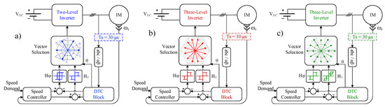
Figure 7.
A high-level control scheme of (a) conventional, (b) vector synthesis and (c) proposed DTC drives. HP: horsepower.
Table 4.
Motor parameters.
4.1. Low-Speed Performance; 20 rpm
Figure 8 shows the performances of the introduced models under a very low rotor speed demand of 20 rpm. At s, a full load-torque of 15 N·m was mounted on the shaft, which was then decoupled at s. Low speed demands such as 20 rpm create very challenging situations for DTC drives. However, choosing the right reference flux and well-tuned hysteresis controllers help to meet very low speed demands. As is shown in Figure 8a–c, in a fraction of a second, the rotor reached the reference speed with no overshoot. When the load was applied ( s) and removed ( s), there were small deviations from the reference of 3 rpm, which were compensated in less than half a second. Since the same speed controller operated all the models, their speed responses were very similar except that of the proposed method, which was less noisy. Figure 8d–f reveals the reasons behind the torque responses. The torque ripple in the conventional DTC was 10 N·m, while it dropped to 6 N·m with vector synthesis DTC, and the proposed model reduced this to only 3 N·m. Figure 8g–i demonstrates the stator flux responses of each model, showing ripples of 0.045, 0.04 and 0.025 Wb for the conventional DTC, vector synthesis and the proposed method, respectively. Flux ripple reduction occurs when the stator current has a more sinusoidal shape, as shown in Figure 8j–l. Besides this, it is an indication of lower harmonic distortion (THD%), which will be discussed later. Figure 8m–o completely differentiates these methods by exhibiting their voltage injection preferences. As stated earlier, the switching table of the proposed method is able to differentiate between large and small torque errors, and it tries to compensate smaller torque errors with smaller voltage vectors, while it switches the larger voltage vectors when it is necessary. Likewise, Figure 8o shows that higher voltage amplitudes were only needed for a fraction of a second in starting condition, and the proposed drive was capable of providing precise torque, flux and speed responses with lower voltage levels even under the condition of full load-torque disturbance.
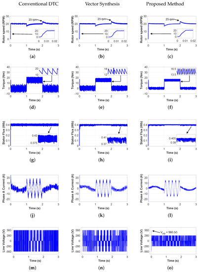
Figure 8.
Simulation results for 20 rpm under 15 N·m load torque disturbance: (a–c) rotor speed response; (d–f) motor torque; (g–i) stator flux; (j–l) input current; (m–o) line voltage.
4.2. Normal-Speed Performance; 1000 rpm
In this step, the drives started with a speed demand of 1000 rpm. A slight overshoot occurred when they reached the reference at s. A 15 N·m load was applied to the shaft, and then removed at s and s, respectively. Figure 9a–c shows the comparable speed responses for all cases with two 3 rpm deviations each for half a second when the load disturbances occurred. Figure 9d–f shows the similar torque responses to those for the low-speed performance for each strategy. The torque ripples were 10, 6, and 3 N·m for conventional DTC, vector synthesis and the proposed method, respectively. During the normal operational range, Figure 9g–i shows the flux ripples of the conventional, vector synthesis and the proposed model, at 0.045, 0.02 and 0.01 Wb, respectively. Figure 9j–l shows the similar performance of this test to that seen in the previous part, and the input voltages presented by Figure 9m–o show the capability of the proposed model for smart voltage vector selection. At higher speeds—especially when a full load is coupled—the need for higher voltage levels increases. Correspondingly, the proposed method triggers higher voltage levels when the torque error passes the tolerable limits.
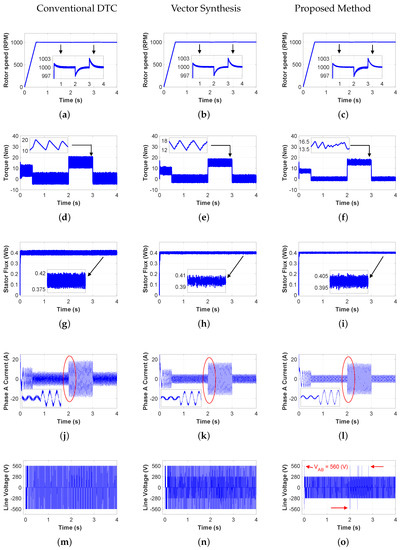
Figure 9.
Simulation results for 1000 rpm under 15 N·m load torque disturbance: (a–c) rotor speed response; (d–f) motor torque; (g–i) stator flux; (j–l) input current; (m–o) line voltage.
4.3. High-Speed Performance; 2000 rpm
Finally, the drives were tested at the high speed of 2000 rpm under no-load (up to ) and load-torque conditions ( s). Although the speed responses, as shown in Figure 10a–c, were similar, the torque responses showed some important details. As mentioned previously, the switching frequency of the vector synthesis method is constant because it injects a slightly different vector at every sampling time to synthesize the desired vector. Thus, the torque response of this method was similar to that demonstrated earlier. The torque ripple of the conventional DTC dropped from 10 to 9 N·m when it exceeded the nominal synchronous speed of 1500 rpm (for a four-pole 50 Hz motor). This method operates based on a variable switching frequency, which mostly depends on the hysteresis bands and rotor speed. Thus, when the rotor speed increases, the switching frequency increases as well. Consequently, the torque ripple decreases to some extent. On the other hand, the torque ripple of the proposed method increased from 3 N·m to 4 N·m when it passed the operational speed range. Figure 10o explains the reason for this by revealing a change in the behavior of the switching table, as it triggered higher voltage levels more frequently in the high-speed region (after s) when the motor entered the constant power region. However, the torque ripple for the proposed method was still lower than the others. Figure 10g–i illustrates the stator fluxes and the effect of the flux weakening algorithm as the rotor speed surpassed the operational range. The flux ripples of the conventional DTC and vector synthesis method experienced a small reduction, to 0.04 and 0.015 Wb, respectively, while the proposed method still maintained this value below 0.01 Wb. Ultimately, Figure 11 illustrates the effectiveness of the proposed technique in maintaining the neutral point balance even during the severe condition of high-speed operation and load-torque disturbance. Because the designated vectors in the switching table were chosen meticulously, voltage unbalance did not occur and the current in ground connection was almost zero (in the range). The same figure also demonstrates the voltage change over one of the inverter gates that did not exceed half of the DC link voltage under the same aforementioned conditions.
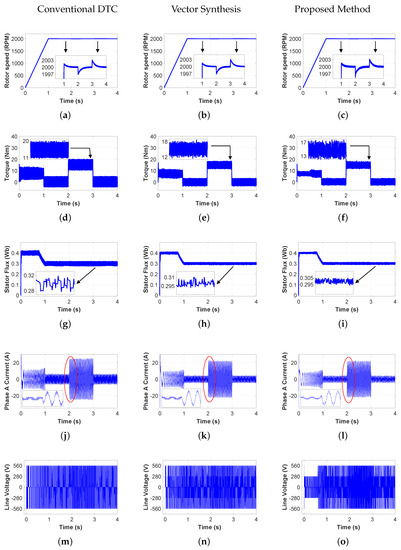
Figure 10.
Simulation results for 2000 rpm under 15 N·m load torque disturbances: (a–c) rotor speed response; (d–f) motor torque; (g–i) stator flux; (j–l) input current; (m–o) line voltage.
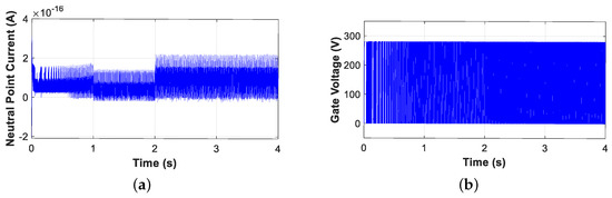
Figure 11.
Current in the neutral point connection (a) and voltage over an inverter gate (b) during the speed command of 2000 rpm and load-torque disturbance.
4.4. Total Harmonic Distortion THD%
Figure 12 depicts the flux trajectories in axes, which is considered to be an excellent representation of the harmonic distortions in a system. The more circular a flux trajectory, the lower the THD% it produces in the system. Figure 13 shows the THD% of the investigated methods at various rotor speeds (from very low to high) and under no-load and load-torque conditions. It was expected that when a load was coupled, as the input current increased, the THD% would decrease, because the share of the fundamentals increased. Since a 3L inverter produces a more sinusoidal current, the harmonics decrease. However, the proposed model contaminates the network with much lower THD% than the vector synthesis method in most operating conditions.
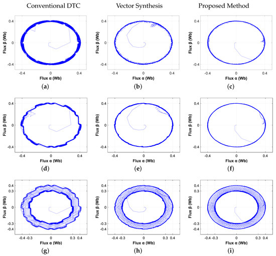
Figure 12.
Stator flux trajectories in axes for (a–c) 20 rpm, (d–f) 1000 rpm, (g–i) 2000 rpm (with flux weakening).
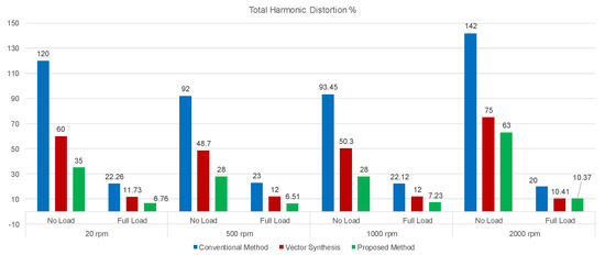
Figure 13.
Total harmonic distortions (THD%) in different scenarios.
5. Conclusions
In this study, we propose a novel technique for a 3L inverter-fed DTC drive. Our method provides an optimized switching table capable of discriminating between large and small torque errors and introducing a third dimension for stator flux control. It requires the use of new hysteresis controllers that allow a greater resolution. Thus, flux and torque commands are issued in three and five levels, respectively. The proposed switching table is organized in such a way to prevent voltage jumps by utilizing the inverter gates with only half of the DC link voltage. Besides this, this model ensures neutral point isolation by providing a voltage balance for each phase. Even for the generation of some vectors for which there are more than one switching pattern, 0 and 1 states are preferred to ensure minimum state changes, resulting in a lower switching frequency. The proposed technique was compared with a conventional model and the vector synthesis DTC model, which has been investigated in great depth for its ripple reduction and smooth switching characteristics. Owing to the fact that all three models used similar well-tuned PI speed controllers, the speed responses were comparable and very accurate. All models demonstrated consistent performances at low, medium, and high speeds (from 20 to 2000 rpm) and under load-torque disturbances. The proposed model showed its efficiency by minimizing the torque ripple by up to 70% and 50% compared with the conventional and vector synthesis DTC models. Its flux ripple was also 78% smaller than the conventional DTC and 50% lower than the vector synthesis method. It also improved THD% and reduced harmonics. However, thethe proposed model runs with a three-times longer sampling delay than the vector synthesis method, which samples every 10 microseconds. This model will help to reduce maintenance costs and mechanical loss by reducing the torque ripple and the stresses on the motor shaft, and it leaves fewer detectable harmonic traces in the network.
Since a three-level inverter is employed, the switching losses are higher compared to the two-level inverter case because the number of IGBTs is doubled. It is noteworthy that, considering similar hysteresis bands, the switching losses for the proposed model will be less than the two-level inverter-fed model as it manages the motor with lower voltage levels, meaning that the switching frequency could also be lower. However, due to the fact that the aim of the method is to reduce the ripples, the hysteresis bands must be chosen accurately. In some cases, there might be a need for a compromise between favoring lower ripple or lower switching losses. However, the proposed model has an advantage over the other three-level inverter-equipped techniques as it prefers lower voltage levels. It is worthy of mention that this advantage is valid for the operational speed range and under the nominal load condition. If the demanded speed exceeds the nominal speed, the proposed model behaves similarly to the other three-level inverter DTC models, as shown in Figure 10o. For future studies, we suggest investigating the experimental results and analyzing the motor and inverter losses, considering the fact that this model operates with lower voltage and current amplitudes for a given motor. Due to the fact that this model does not require additional equipment, the only concern is the precise tuning of the hysteresis bands and the dead-time of the inverter when considering the sampling time of the control loop.
Author Contributions
Conceptualization, Y.F. and H.C.; methodology, Y.F., M.A. and H.C.; software, Y.F.; validation, Y.F., M.A., H.C. and S.K.; formal analysis, H.C. and S.K.; investigation, Y.F., M.A., H.C. and S.K.; resources, H.C. and S.K.; data curation, Y.F.; writing—original draft preparation, Y.F. and M.A.; writing—review and editing, Y.F., M.A., H.C. and S.K.; visualization, Y.F., M.A., H.C. and S.K.; supervision, H.C. and S.K.; project administration, H.C. and S.K.;. All authors have read and agreed to the published version of the manuscript.
Funding
This research received no external funding.
Conflicts of Interest
The authors declare no conflict of interest.
Abbreviations
| List of Symbols: | |
| Actual, reference, and nominal stator flux | |
| Stator voltage and current vector | |
| Actual and reference Electromagnetic torques | |
| Voltage and current in abc frame | |
| Nominal and rotor speeds | |
| Voltage and current in frame | |
| Stator and rotor resistances | |
| Stator flux components in frame | |
| Stator, rotor, and mutual inductances | |
| Stator flux angle | |
| Integral and proportional gains | |
| Torque and flux hysteresis commands | |
| p | Motor pole pairs |
| Revolutions per minute | |
| Weber (unit) | |
| Milli henry (unit) | |
| Kilowatt (Unit) | |
| Horse power (unit) | |
| Newton-meter (Unit) | |
| Hertz (unit) | |
| List of Acronyms: | |
| PIC | Proportional integral controller |
| DTC | Direct torque control |
| THD | Total harmonic distortion |
| FOC | Field oriented control |
| 3L-NPC | Three-level neutral-point clamped |
| MLI | Multi-level inverter |
References
- Sun, X.; Diao, K.; Yang, Z.; Lei, G.; Guo, Y.; Zhu, J. Direct Torque Control Based on a Fast Modeling Method for a Segmented-Rotor Switched Reluctance Motor in HEV Application. IEEE J. Emerg. Sel. Top. Power Electron. 2019. [Google Scholar] [CrossRef]
- Casadei, D.; Profumo, F.; Serra, G.; Tani, A. FOC and DTC: Two viable schemes for induction motors torque control. IEEE Trans. Power Electron. 2002, 17, 779–787. [Google Scholar] [CrossRef]
- Zhang, Y.; Zhu, J. Direct Torque Control of Permanent Magnet Synchronous Motor With Reduced Torque Ripple and Commutation Frequency. IEEE Trans. Power Electron. 2011, 26, 235–248. [Google Scholar] [CrossRef]
- Buja, G.; Kazmierkowski, M. Direct torque control of PWM inverter-fed AC motors—A survey. IEEE Trans. Ind. Electron. 2004, 51, 744–757. [Google Scholar] [CrossRef]
- Zhang, Q.; Deng, J.; Fu, N. Minimum Copper Loss Direct Torque Control of Brushless DC Motor Drive in Electric and Hybrid Electric Vehicles. IEEE Access 2019, 7, 113264–113271. [Google Scholar] [CrossRef]
- Mohan, D.; Zhang, X.; Foo, G.H.B. Generalized DTC Strategy for Multilevel Inverter Fed IPMSMs With Constant Inverter Switching Frequency and Reduced Torque Ripples. IEEE Trans. Energy Convers. 2017, 32, 1031–1041. [Google Scholar] [CrossRef]
- Yan, N.; Cao, X.; Deng, Z. Direct Torque Control for Switched Reluctance Motor to Obtain High Torque–Ampere Ratio. IEEE Trans. Ind. Electron. 2019, 66, 5144–5152. [Google Scholar] [CrossRef]
- Farajpour, Y. Modifying the Structure of a Fuzzy Controller to Improve Speed Estimation Response in Rotor-Flux MRAS DTC Drive. Int. J. Sci. Res. Sci. Eng. Technol. (IJSRSET) 2018, 4, 248–258. [Google Scholar]
- Holakooie, M.H.; Ojaghi, M.; Taheri, A. Modified DTC of a Six-Phase Induction Motor With a Second-Order Sliding-Mode MRAS-Based Speed Estimator. IEEE Trans. Power Electron. 2019, 34, 600–611. [Google Scholar] [CrossRef]
- Foo, G.; Sayeef, S.; Rahman, M. Low-Speed and Standstill Operation of a Sensorless Direct Torque and Flux Controlled IPM Synchronous Motor Drive. IEEE Trans. Energy Convers. 2010, 25, 25–33. [Google Scholar] [CrossRef]
- Alsofyani, I.; Kim, K.; Lee, S.; Lee, K. A Modified Flux Regulation Method to Minimize Switching Frequency and Improve DTC-Hysteresis-Based Induction Machines in Low-Speed Regions. IEEE J. Emerg. Sel. Top. Power Electron. 2019, 7, 2346–2355. [Google Scholar] [CrossRef]
- Alsofyani, I.; Idris, N. Simple Flux Regulation for Improving State Estimation at Very Low and Zero Speed of a Speed Sensorless Direct Torque Control of an Induction Motor. IEEE Trans. Power Electron. 2016, 31, 3027–3035. [Google Scholar] [CrossRef]
- Lascu, C.; Trzynadlowski, A. A sensorless hybrid DTC drive for high-volume low-cost applications. IEEE Trans. Ind. Electron. 2004, 51, 1048–1055. [Google Scholar] [CrossRef]
- Lee, K.; Blaabjerg, F. Sensorless DTC-SVM for Induction Motor Driven by a Matrix Converter Using a Parameter Estimation Strategy. IEEE Trans. Ind. Electron. 2008, 55, 512–521. [Google Scholar] [CrossRef]
- Lascu, C.; Trzynadlowski, A. Combining the principles of sliding mode, direct torque control, and space-vector modulation in a high-performance sensorless AC drive. IEEE Trans. Ind. Appl. 2004, 40, 170–177. [Google Scholar] [CrossRef]
- Lascu, C.; Jafarzadeh, S.; Fadali, M.S.; Blaabjerg, F. Direct Torque Control With Feedback Linearization for Induction Motor Drives. IEEE Trans. Power Electron. 2017, 32, 2072–2080. [Google Scholar] [CrossRef]
- Lee, J.; Choi, C.; Seok, J.; Lorenz, R. Deadbeat-Direct Torque and Flux Control of Interior Permanent Magnet Synchronous Machines With Discrete Time Stator Current and Stator Flux Linkage Observer. IEEE Trans. Ind. Appl. 2011, 47, 1749–1758. [Google Scholar] [CrossRef]
- Sun, X.; Hu, C.; Lei, G.; Guo, Y.; Zhu, J. State Feedback Control for a PM Hub Motor Based on Gray Wolf Optimization Algorithm. IEEE Trans. Power Electron. 2020, 35, 1136–1146. [Google Scholar] [CrossRef]
- Habibullah, M.; Lu, D.D.; Xiao, D.; Rahman, M.F. A Simplified Finite-State Predictive Direct Torque Control for Induction Motor Drive. IEEE Trans. Ind. Electron. 2016, 63, 3964–3975. [Google Scholar] [CrossRef]
- Sun, X.; Chen, L.; Yang, Z.; Zhu, H. Speed-Sensorless Vector Control of a Bearingless Induction Motor With Artificial Neural Network Inverse Speed Observer. IEEE/ASME Trans. Mech. 2013, 18, 1357–1366. [Google Scholar] [CrossRef]
- Vafaie, M.; Dehkordi, B.; Moallem, P.; Kiyoumarsi, A. Minimizing Torque and Flux Ripples and Improving Dynamic Response of PMSM Using a Voltage Vector With Optimal Parameters. IEEE Trans. Ind. Electron. 2016, 63, 3876–3888. [Google Scholar] [CrossRef]
- Cho, Y.; Bak, Y.; Lee, K. Torque-Ripple Reduction and Fast Torque Response Strategy for Predictive Torque Control of Induction Motors. IEEE Trans. Power Electron. 2018, 33, 2458–2470. [Google Scholar] [CrossRef]
- Alsofyani, I.; Bak, Y.; Lee, K. Fast Torque Control and Minimized Sector-Flux Droop for Constant Frequency Torque Controller Based DTC of Induction Machines. IEEE Trans. Power Electron. 2019, 34, 12141–12153. [Google Scholar] [CrossRef]
- Mohan, D.; Zhang, X.; Foo, G. A Simple Duty Cycle Control Strategy to Reduce Torque Ripples and Improve Low-Speed Performance of a Three-Level Inverter Fed DTC IPMSM Drive. IEEE Trans. Ind. Electron. 2017, 64, 2709–2721. [Google Scholar] [CrossRef]
- Niu, F. A Simple and Practical Duty Cycle Modulated Direct Torque Control for Permanent Magnet Synchronous Motors. IEEE Trans. Power Electron. 2019, 34, 1572–1579. [Google Scholar] [CrossRef]
- Hakami, S.; Alsofyani, I.; Lee, K. Torque Ripple Reduction and Flux-Droop Minimization of DTC With Improved Interleaving CSFTC of IM Fed by Three-Level NPC Inverter. IEEE Access 2019, 7, 184266–184275. [Google Scholar] [CrossRef]
- Mohan, D.; Zhang, X.; Foo, G. Three-Level Inverter-Fed Direct Torque Control of IPMSM With Constant Switching Frequency and Torque Ripple Reduction. IEEE Trans. Ind. Electron. 2016, 63, 7908–7918. [Google Scholar] [CrossRef]
- Rodriguez, J.; Bernet, S.; Wu, B.; Pontt, J.; Kouro, S. Multilevel Voltage-Source-Converter Topologies for Industrial Medium-Voltage Drives. IEEE Trans. Ind. Electron. 2007, 54, 2930–2945. [Google Scholar] [CrossRef]
- Yao, W.; Hu, H.; Lu, Z. Comparisons of Space-Vector Modulation and Carrier-Based Modulation of Multilevel Inverter. IEEE Trans. Power Electron. 2008, 23, 45–51. [Google Scholar] [CrossRef]
- Busquets-Monge, S.; Alepuz, S.; Bordonau, J.; Peracaula, J. Voltage Balancing Control of Diode-Clamped Multilevel Converters With Passive Front-Ends. IEEE Trans. Power Electron. 2008, 23, 1751–1758. [Google Scholar] [CrossRef]
- Dalessandro, L.; Round, S.; Kolar, J. Center-Point Voltage Balancing of Hysteresis Current Controlled Three-Level PWM Rectifiers. IEEE Trans. Power Electron. 2008, 23, 2477–2488. [Google Scholar] [CrossRef]
- Naganathan, P.; Srinivas, S.; Ittamveettil, H. Five-level torque controller-based DTC method for a cascaded three-level inverter fed induction motor drive. IET Power Electron. 2017, 10, 1223–1230. [Google Scholar] [CrossRef]
- Del Toro, X.; Garcia, A.; Arias, M.; Jayne, P. Witting Direct Torque Control of Induction Motors Utilizing Three-Level Voltage Source Inverters. IEEE Trans. Ind. Electron. 2008, 55, 956–958. [Google Scholar] [CrossRef]
- Sapin, A.; Steimer, P.; Simond, J. Modeling, Simulation, and Test of a Three-Level Voltage-Source Inverter With Output LC Filter and Direct Torque Control. IEEE Trans. Ind. Appl. 2007, 43, 469–475. [Google Scholar] [CrossRef]
- Tang, Q.; Ge, X.; Liu, Y.; Hou, M. Improved switching-table-based DTC strategy for the post-fault three-level NPC inverter-fed induction motor drives. IET Electr. Power Appl. 2018, 12, 71–80. [Google Scholar] [CrossRef]
- Wang, S.; Li, C.; Che, C.; Xu, D. Direct Torque Control for 2L-VSI PMSM Using Switching Instant Table. IEEE Trans. Ind. Electron. 2018, 65, 9410–9420. [Google Scholar] [CrossRef]
- Zeng, Z.; Zhu, C.; Jin, X.; Shi, W.; Zhao, R. Hybrid Space Vector Modulation Strategy for Torque Ripple Minimization in Three-Phase Four-Switch Inverter-Fed PMSM Drives. IEEE Trans. Ind. Electron. 2017, 64, 2122–2134. [Google Scholar] [CrossRef]
- Zhang, Y.; Zhu, J.; Zhao, Z.; Xu, W.; Dorrell, D. An Improved Direct Torque Control for Three-Level Inverter-Fed Induction Motor Sensorless Drive. IEEE Trans. Power Electron. 2012, 27, 1502–1513. [Google Scholar] [CrossRef]
- Jung, K.; Suh, Y. Analysis and Control of Neutral-Point Deviation in Three-Level NPC Converter Under Unbalanced Three-Phase AC Grid. IEEE Trans. Ind. Appl. 2019, 55, 4944–4955. [Google Scholar] [CrossRef]
- Foo, G.H.B.; Zhang, X. Robust Direct Torque Control of Synchronous Reluctance Motor Drives in the Field-Weakening Region. IEEE Trans. Power Electron. 2017, 32, 1289–1298. [Google Scholar] [CrossRef]


© 2020 by the authors. Licensee MDPI, Basel, Switzerland. This article is an open access article distributed under the terms and conditions of the Creative Commons Attribution (CC BY) license (http://creativecommons.org/licenses/by/4.0/).