1. Introduction
Fuel Cells are highly efficient devices for converting chemical energy bonded in fuel, like hydrogen, into electrical energy. Within this process, thermal energy is generated in parallel, which can be used in combined heat and power (CHP) systems e.g., in stationary applications. Even though hydrogen is the favored fuel for fuel cells, but the lag of area-wide hydrogen supply leads to the substitution of hydrogen by other fuels e.g., natural gas. For the use in CHP systems, natural gas has to be converted into hydrogen-rich reformate by a chemical process, like steam reforming (Equation (1)) [
1].
Carbon monoxide is formed as a result of steam reforming. In contrast to other fuel cell technologies, like solid oxide fuel cells (SOFC) or high-temperature proton exchange membrane fuel cells (HT-PEMFC), low-temperature PEMFC (LT-PEMFC) are prone to CO poisoning, even at low concentrations in the ppm range [
2]. State of the art fuel processor in stationary fuel cell CHP-systems use a multi-step cleaning process to reduce the CO concentration in a steam reformed reformate. In a first step, CO is reduced by a two-step water gas shift reaction (Equation (2)), which is commonly called high and low-temperature shift. A fine cleaning is used, e.g., selective methanation (Equation (3)), in order to reduce the CO content even further [
3]. By these techniques, the CO concentration can be reduced down to 10 ppm [
1].
Despite the extensive purification of the reformate, CO still can lead to performance loss in LT-PEMFC. The adsorption of CO can be described as a competition mechanism [
2,
4,
5]. CO can adsorb on the platinum surface, similar to hydrogen (Equations (4) and (5)) [
4].
Much effort has been made to increase the CO tolerance of LT-PEMFC. The most common technique to increase CO tolerance is the use of bimetallic catalysts, like e.g., Pt-Ru. The increase in CO tolerance by Pt-Ru is postulated by two effects, an electronic as well as a ligand mechanism. The electronic mechanism postulates a modification of the platinum electronic structure, leading to a weakening of the Pt-CO bond (Equation (6)). On the other hand, the ligand mechanism postulates a promoted oxidation of CO due to the formation of e.g., hydroxide groups on the ruthenium (Equation (7)) [
6,
7].
A major disadvantage of the platinum-ruthenium catalysts is the discharge of ruthenium, which is accelerated in an acidic environment at high cell potentials, as can occur during start/stop processes in the LT-PEMFC [
8]. The increased discharge of ruthenium primarily leads to a decrease in CO tolerance. This decrease could lead to a higher loss of performance due to CO poisoning, especially at long term operation. In addition, the literature results could show the migration of ruthenium to the cathode, as a result of which the performance of the membrane electrode assembly (MEA) was reduced [
9,
10,
11].
Besides the use of Pt-Ru catalysts, air bleed is the most common technique to recover fuel cell performance under CO influence [
12,
13,
14]. In this case, the atmospheric oxygen is used to oxidize the CO on the anode side (Equation (8)) [
4].
Numerous articles have already shown the effectiveness of the air bleed in the LT-PEMFC [
13,
14,
15]. Work conducted by Hedström et al. and Du et al. reveal that the operation of LT-PEMFC at high CO concentrations of more than 100 ppm is possible with a suitable air bleed [
15,
16]. Despite its high effectiveness, air bleed can lead to irreversible degradation. Inaba et al. showed that the use of air bleed (5% air in reformate) can lead to degradation of anode catalyst and membrane through the formation of hydrogen peroxide (H
2O
2) [
17]. These findings are in good agreement with the results from Delgado et al. In a direct comparison, MEAs with 1% air bleed showed a ten times higher degradation rate [
18]. In contrast, the results of Sung et al. did not show a significant increase in degradation rate after a 3000 h long term test at 5% air bleed [
19].
Therefore, the detection of CO within the CHP system and determination of the correct air bleed dosage are of enormous importance. This is even more pronounced if one takes into account that an additional unit in the form of a compressor or something similar has to be integrated into the system for the air bleed dosage. The additional energy required for that decreases the energy balance of the system [
20]. Recently, publications by Klages et al. and Tjønnås et al. have been published regarding the development of air bleed controller for the usage in LT-PEMFC based CHP systems. Using a dual controller approach authors could achieve a stable stack operation in the presence of CO concentrations of 16 ppm. Besides, the authors used an even simpler approach for air bleed control in the form of a heuristic algorithm. In this case, air bleed is increased stepwise in small amounts to detect and regenerate voltage losses caused by CO [
21,
22].
The literature review shows that the degradation of the anode catalyst due to the loss of ruthenium is still a current issue in reformate-operated stationary CHP systems that are based on LT-PEMFC. However, research results regarding CO tolerance changes on MEA or stack level with Pt-Ru catalysts have hardly been found. In the first part of this article, we show the influence of the stack age on the CO tolerance and the regeneration behavior of two LT-PEMFC short stacks. Therefore, to the best of the authors’ knowledge, the results of MEAs with different operation times (begin of life (BoL), 10,000 and 16,000 h of operation) under different CO concentrations (2 and 25 ppm CO) will be compared for the first time The literature research showed that the use of air bleed as a regeneration approach in the LT-PEMFC is widespread and very efficient. However, the use of air bleed can contribute to the increased degradation of the MEAs. Therefore, it is essential to detect CO in reformate and, if necessary, to regenerate it with the smallest possible amount of air bleed. In the second part of this article, the development of a simple heuristic algorithm for the detection and regeneration of CO-related performance losses will be shown. The first results of the commissioning in a test bench environment are also shown. All of the work in this article was carried out as part of the project “LifetimeINH5000” (grant no. 03ETB004B) founded by the German Federal Ministry of Economic Affairs and Energy (BMWi). In the project, strategies are developed to increase the efficiency and lifetime of a 5 kWel CHP system based on an LT-PEMFC. Besides the improvement of existing materials, stack, and system design, in situ recovery procedures should also be developed and integrated into system operation.
2. Materials and Methods
2.1. Short Stack Testing
Two stacks have been tested at different aging stages in order to investigate the influence of CO on cell voltage. Both short stacks each consisting of six single cells have been provided by Inhouse Engineering GmbH, Germany. The active area of each cell is around 200 cm². Stack design and layout are based on the system stack level. All of the used MEAs are commercially available with a Pt-Ru/C catalyst at the anode, developed for reformate operation. Cathode catalyst is standard Pt/C. MEA properties, such as catalyst loading, cannot be displayed due to confidential reasons. The first stack (Stack 01) consists of six pristine MEAs, whereas the long term operated second stack (Stack 02) is part of a durability test at inhouse engineering GmbH since 2016. Furthermore, cells 1–3 already completed 16,000 h of measurement, whereas cells 4–6 performed 10,000 h. During the durability test at inhouse, the stack has been operated with a CO-free synthetic reformate (75% H2 and 25% CO2), in a load cycling protocol between 30 and 80 A. All of the measurements shown in this paper have been carried out on a fuel cell test bench from FuelCon AG, called FuelCon Evaluator S5. Both of the stacks have been operated at standard operating parameters provided by inhouse engineering GmbH. Thereby, the stack inlet temperature was 65 °C. At the anode synthetic reformate (75% H2 + 25% CO2) at a stoichiometry λ(An) of 1.3 and a dew point at gas inlet of 60 °C has been used. At the cathode site, air was used with a stoichiometry λ(Ca) of 2 and a dew point of 60 °C. The gas inlet temperatures were set to 65 °C on both sites to avoid condensation. CO measurements were carried out by using a premixed gas (Air Liquide, France) containing 2.7 mol-ppm or 33 mol-ppm CO in H2, respectively. The desired CO concentrations of 2 and 25 ppm CO have been achieved by diluting the premixed gas with CO2. To regenerate the stack after CO poisoning, compressed air was diluted into the reformate stream. Based on the hydrogen flowrate, air bleed concentrations of 0.2 to 5.0 Vol.-% could be achieved by using a mass flow controller.
2.2. Algorithm Development
One way to recover voltage losses caused by CO poisoning in LT-PEMFC is the use of air bleed. Even though it is a rather simple approach, air bleed has several drawbacks, like the formation of hydroxide peroxide, which leads to membrane and catalyst degradation. Therefore, the detection of CO and the dosing of air bleed are two key elements for a long-term system operation under reformate conditions. Within LifetimeINH5000, a heuristic algorithm has been developed, in order to detect and regenerate voltage losses that are induced by CO poisoning.
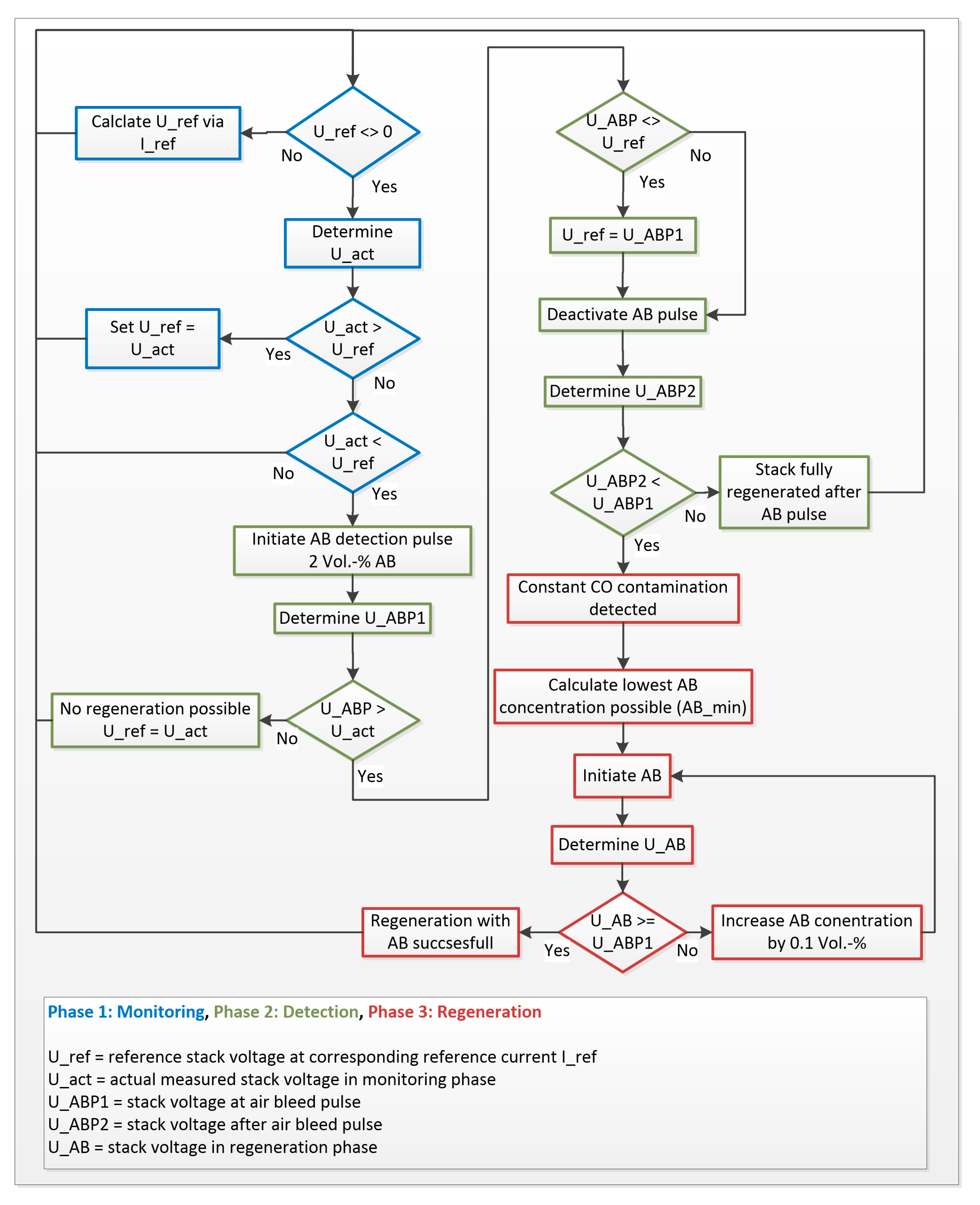
Figure 1 shows the basic work principle of the presented algorithm.
The algorithm is divided into three phases and it is briefly described. Phase 1, the monitoring phase, includes the constant monitoring of the stack voltage (U_act) and the comparison with a reference voltage (U_ref). U_ref is calculated based on a Begin of Life polarization curve. For the calculation of U_ref, the actual stack current (I_ref) is used as a reference value. As long as the measured delta between U_act and U_ref is smaller than the sum of both measurement errors, the algorithm remains in an idle mode. If U_act is significantly higher than U_ref, U_ref will be updated to U_act. In the case that U_act is significantly lower than U_ref, the detection of CO will be initiated in phase 2, the detection phase. The algorithm initiates an air bleed pulse of 2 Vol.-% for 10 min. At the end of the air bleed pulse, the stack voltage is determined (U_ABP1) and compared to U_act. If the stack voltage under air bleed does not increase, the regeneration with air bleed is impossible. In this case, the reference voltage U_ref is overwritten with the last determined stack voltage U_act to suppress the continuous activation of the detection phase.
In the case of CO poisoning, stack voltage increases under air bleed influence. By comparing U_ABP1 with the reference voltage U_ref, the algorithm determines the degree of regeneration. The total voltage loss consists of a reversible and irreversible part. Overlay of irreversible degradation that cannot be regenerated by the air bleed is no longer taken into account, by updating the reference voltage U_ref to the value of U_ABP1. A constant air bleed is not required in the case of low CO concentrations and stack currents. Following the air bleed pulse, the stack voltage is determined after ten additional minutes without air bleed (U_ABP2) and compared with the values of U_ABP1. Low CO concentrations are assumed if the stack voltage hardly drops during this period. Thus, the initiation of a constant air bleed seems unnecessary. However, if the stack voltage drops significantly without air bleed, a constant air bleed will be needed. For this purpose, in phase 3, the regeneration phase, based on the current stack current I_ref, the minimum possible air bleed concentration is calculated and fed to the stack. The stack voltage (U_AB) is now continuously recorded and compared with U_ABP1. If U_AB is smaller than U_ABP1, air bleed concentration is increased gradually.
3. Results and Discussion
Performance loss that is caused by CO poisoning is a big issue for LT-PEMFC based CHP systems. Two short stacks have been evaluated under identical conditions to determine the influence of CO on the stack performance in different aging stages. After a boot phase, the stacks have been conditioned at constant load of 80 A for at least four hours were a polarization curve was measured to determine the actual performance. Afterward, additional CO measurements, starting with the lowest CO concentration, have been carried out.
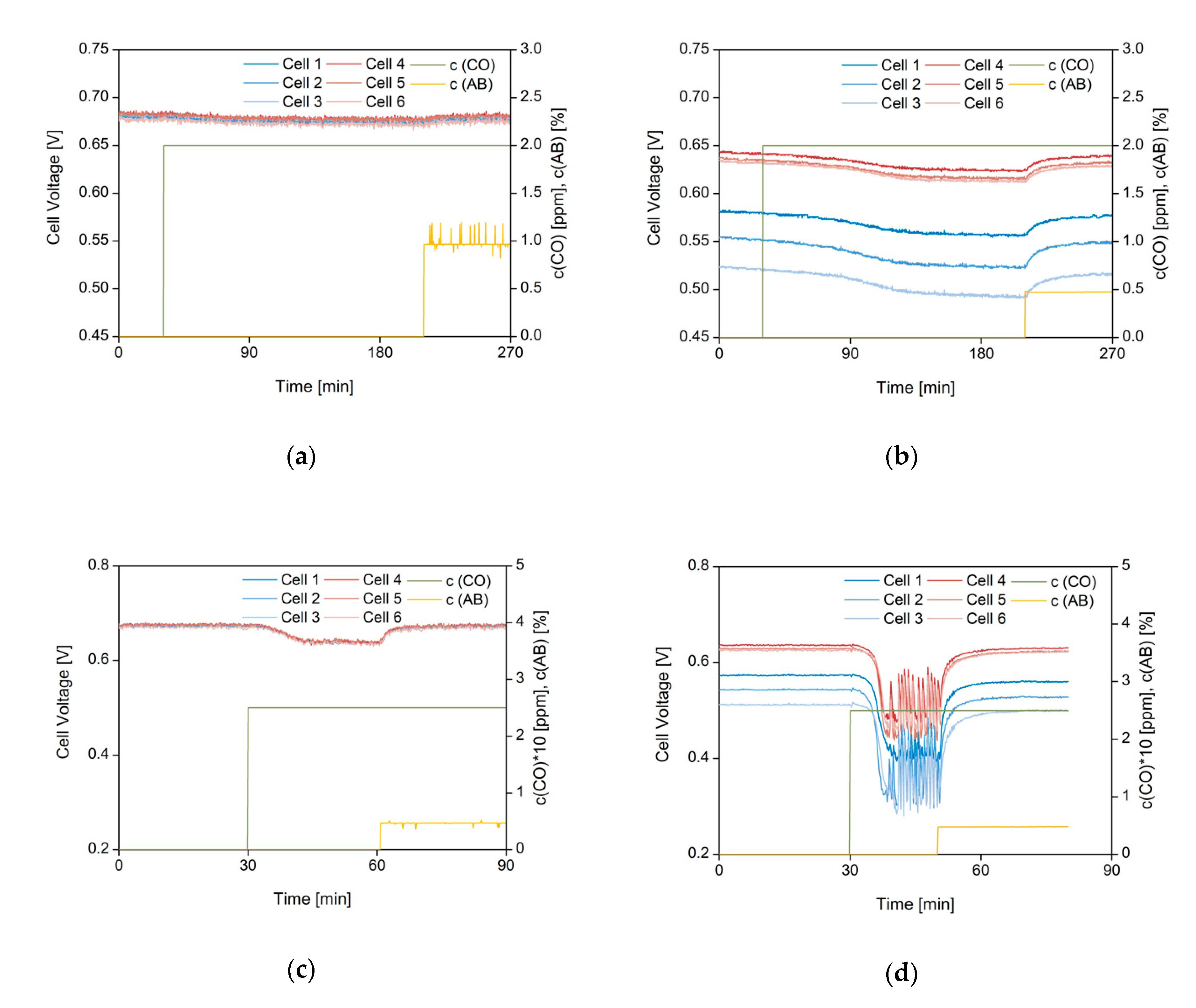
Figure 2 presents the voltage versus time curves of both stacks.
Figure 2a,c present the voltage versus time curves of Stack 01 with 2 and 25 ppm CO. In the case of 2 ppm CO, the cell voltages remain stable. After three hours at 2 ppm CO, an average voltage drop of only 5 mV/cell was observed, which is within the measurement error of the used cell voltage monitor. Increasing the CO concentration to 25 ppm leads to a higher average voltage loss of 36 mV/cell. In contrast to the earlier mentioned measurement, the voltage drop of all six cells is completed after 20 min. In both cases, voltage regeneration via air bleed leads to a high voltage recovery of more than 99% (see
Table 1).
These results indicate that, at Begin of Life, small amounts of CO up to 2 ppm, are not detectable with the used setup. As expected, the higher CO concentration leads to a higher average voltage loss. The selected CO concentration of 25 ppm is an already high amount of CO and it should be avoided due to decreasing efficiency in a real system. Even though, an operation without air bleed would be possible at this level. By adding 0.5 Vol.-% air bleed, the cell voltage regenerates immediately. The used air bleed concentration is also in good agreement with data published in literature [
21].
The cell voltage response of Stack 02, with already aged cells, is presented in
Figure 2b,d. When compared to Stack 01, the voltage loss of Stack 02 increased through the influence of 2 ppm CO. The measured average voltage loss for the cells 4–6 is 19 mV/cell. Cells 1–3 with already 16,000 h of operation lost 27 mV/cell under same conditions. In comparison to Stack 01 the voltage loss caused by 2 ppm increases by a factor of four after 10,000 h and increases to a factor of six after 16,000 h of operation, respectively. An increase in CO concentration to 25 ppm supports these findings even further. As can be seen in
Figure 2d injection of 25 ppm CO into the fuel stream leads to an almost immediately and dramatic average voltage loss. In contrast to all other measurements cell voltages show an unstable characteristic. In fact, they start to fluctuate. This kind of voltage fluctuation could indicate a self-cleaning process of the anode catalyst layer. Investigations of Jung Geon et al. showed that CO oxidizes at 0.3 V in LT-PEMFC when bonded to Pt-Ru/C catalyst [
23]. The catalyst surface is again accessible for hydrogen and the cell voltages increases, due to CO oxidation. For cells 1–3, the cell voltages start to recover at about 0.3 V. For cells 4–6 an average voltage loss of 167 mV/cell could be observed. The voltage loss of cells 1–3 is in the range of 208 mV/cell. Because of the large fluctuation of the cell voltage, normal operation of the stack or system is impossible without air bleed. By adding small amounts of air into the anode gas stream cell voltages regenerate fast and stabilize. Furthermore, by adding air bleed 95% of the initial cell voltage loss could be regenerated. Based on these results, it is clear that the CO resistance of a stack decreases with increasing operation time. Even small amounts of CO lead to high voltage and power loss of the stack. The reasons for an increased CO sensitivity could be the loss of Ru catalyst or a general loss of active surface area [
24]. Based on the presented results aged MEAs will be investigated ex situ via SEM, TEM, and µ-CT in order to investigate the CO sensitivity increase. Nevertheless, the results show the necessity of CO detection and regeneration. A simple control algorithm based on cell voltage has been developed and tested in order to achieve both targets. After implementation of the algorithm into the test bench programming, a first test has been carried out with Stack 01.
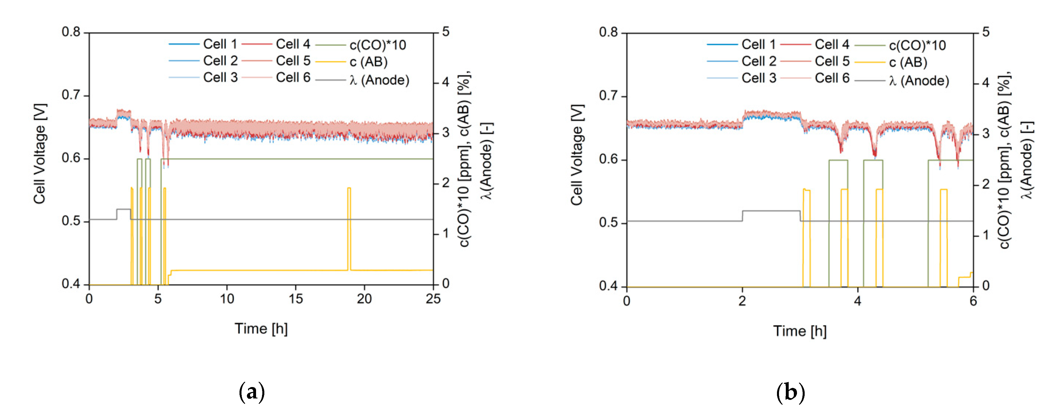
Figure 3 presents the result of this measurement.
The algorithm has been activated after start up and conditioning of the stack for four hours. In the first two hours of operation, the algorithm is in idle mode after adjustment of the reference voltage U_ref. A change in stoichiometry has been used to simulate a non-CO related voltage drop. As one can clearly see in
Figure 3b, the stoichiometry is raised to 1.5 on the anode side after two hours of operation. The voltage gain is detected by the algorithm and saved as new reference voltage. After one hour at 1.5, the stoichiometry is set back to 1.3 again. The provoked voltage drop initiates the first detection pulse with air bleed. Current voltage is saved as reference because no voltage increase could be detected during air bleed pulse. The detection of CO poisoning was tested by adding 25 ppm CO into the anode gas stream. Again, the provoked voltage drop triggers the detection via air bleed pulse. As can be seen in
Figure 3b, the detection of CO induced voltage drop is successful after four hours. Long term operation with the algorithm has been tested beginning in
Figure 3a after five hours. After successful identification of CO, the algorithm initiates a constant air bleed. An air bleed concentration of just 0.3 Vol.-% is needed to reach complete voltage regeneration. Small amounts of air bleed are therefore preferable for long term operation of the stack, as higher oxygen concentration could lead to higher degradation [
25]. In comparison to the work of Klages et al., the algorithm used in this paper has been modified with an air bleed pulse. Via this pulse the full regeneration potential of the stack can be measured within a few minutes of operation. Under normal operating conditions, the system is influenced by external factors, causing changes in stack current and voltage. Each change will end up in an interruption of the air bleed adjustment. Therefore, the air bleed pulse used in the shown algorithm offers the system control the possibility to decide individually. Either the current parameters remain constant until air bleed adjustment is completed or the adjustment to a period in which system parameter usually remain stable is postponed.
4. Conclusions and Outlook
The developed air bleed regeneration process is a simple but efficient method to recover reformate gas-fed LT-PEMFC stack performance losses in stationary applications under CO influence. The method uses a heuristic control algorithm to detect CO in reformate and, if required, to regenerate it with the smallest amount of air bleed. As expected, a correlation between CO concentration, performance losses, as well as required air bleed flow during the operation was found and validated. The short stack tests were performed with different typical CO concentrations. Additionally, the influence of operation time on the CO sensitivity of an LT-PEM short stack has been investigated. When considering oxygen-based degradation effects, the algorithm uses an air bleed pulse as well as reference values for a precise determination of the regeneration potential and small as possible amounts of air. The results have shown that all voltage losses could be regenerated, and also aged stacks could be operated successfully at low air concentrations of 0.5 Vol-%. Hence, the proposed method has a high potential for automated regeneration procedures in reformat fed LT-PEMFC systems. However, it must be said that the procedure qualification within the system by using components like pumps and sensors has to be proved. Therefore, the algorithm and prototypical components are going to implement in three CHP systems under real operation for further evaluation. In this regard, the decrease in CO tolerance will be investigated at different operation conditions.


