1. Introduction
In recent years, a significant increase in the use of low-power generators by both industrial and individual users has been noticeable, e.g., among generators with diesel engine setups [
1]. On the one hand, the installation of low-power generators increases the reliability of the operation of the electrical installation, and thus minimizes losses in the event of a power cut from the industrial network, increasing comfort and safety for households at the same time. On the other hand, the use of generating sets is associated with operational problems and ensuring usage safety.
In the case of high-power generators operating in professional power plants, the use of many protection systems are required, which are designed for rapid interference elimination based on various measurement signals, e.g., measurements based on the method of symmetrical components [
2,
3]. On the other hand, the occurrence of low- and medium-power generators in grid structures makes it difficult to correctly select adequate protections, especially in hybrid power supply systems, where the installation can be powered from the power system or a generator set operating at low-voltage (LV) and medium-voltage (MV) levels. The protection used in these grids is mainly apparatuses in the form of molded case circuit breakers, fuse switch-disconnectors, and circuit breakers [
4,
5,
6].
Due to the above, an important aspect related to the safety and reliability of hybrid installations is the analysis of generator short-circuit currents. Analyzing the transient states that appear during the occurrence of short-circuits in hybrid systems makes it possible to present the nature of transient phenomena in installations powered from backup sources of electricity [
7]. This exposes the problem associated with the selection of protection devices in such installations in terms of their correct operation. This aspect is important due to the widespread use of hybrid installations to power priority receivers, e.g., fire protection installations.
The literature has widely described the phenomena connected with the generator short-circuits [
8,
9,
10,
11], but the authors have rarely examined these phenomena in the context of low-power hybrid systems, for example, diesel generators (DGs), where the characteristic low values of the time constants cause fast reaching of the steady-state short-circuit current (which is low as well). The analysis of the obtained results allowed the verification of individual applications of generators in electrical installations in the context of the selection or checking of the installed safety equipment.
2. Synchronous Generators Short-Circuits in Installations
Synchronous generators in the Polish national power system (KSE) are the basic machines used in main power plants (the main generators nodes of KSE) of this system. Also, in the case of generating sets installed as a backup energy sources or electricity sources in places without access to the power grid, synchronous generators are widely used.
Depending on the location of the short-circuit in the power supply system, the short-circuits near and far from generator can be distinguished. These cases have been presented in detail in publications [
10,
11,
12]. Considering the case of using low- and medium-power generators as electricity locations, one can talk about the occurrence of electricity near the generator short-circuit.
The short-circuit current of the cylindrical generator can be described by the following Formulas [
10,
11,
13]:
where
maximum phase voltage value,
—phase shift angle,
—synchronous reactance,
—transient reactance,
—subtransient reactance,
—aperiodic time constant [s].
Function given by Formula (2) refers to the three-phase short-circuits.
In the case of dependence on the short-circuit current of generators with salient poles, different values of direct and quadrature parameters of the generator should be taken into account [
10,
11,
14,
15]:
where
Both Formulas (1) and (3) refer to three-phase short-circuits. This type of short-circuit does not cause asymmetry in the load of individual generator windings.
An important problem associated with the operation of low-power synchronous generators are the relatively small values of the subtransient and transient electromagnetic time constants of these generators, generally defined as:
where
—direct axis short-circuit transient time constant [s],
—direct axis short-circuit sub-transient time constant [s],
—direct axis transient inductance [H],
—direct axis sub-transient inductance [H],
—armature resistance [Ω].
Due to fact that in low-power generators, the time constants take values from a few to several dozen milliseconds, the processes of displacing the magnetic flux from the rotor pass away in a short time and the generator quickly goes to steady-state short-circuit.
An important issue related to the analysis of short-circuit currents in installations with a low-power synchronous generator is the resistance of conductors, as well as their inductive reactance. It should be noticed that unlike commercial power, the engineering near the generator short-circuits, as well as the modification of the formula for the near the short-circuit current of a generator, are slightly different. In Formula (1), considering the generators operating in the KSE, in the case of a short-circuit on a transmission line close to the power plant, one should also take into account the line reactance
to the short-circuit location, which defines the relationship:
where time constant are as follows:
On the other hand, for the analyzed case of a low-power generator working in a low-voltage grid, the considerations should also take into account the wire resistance. The reason is that in the low-voltage installations the resistance
can have values many times higher than the value of the short-circuit reactance. The near to generator short-circuit current of the low-voltage generator can be calculated from Formula (9).
where
—short-circuit steady-state component
—short-circuit transient component
—short-circuit subtransient component
where time constants are defined as:
Considering the case of a symmetrical short-circuit in a hybrid power supply system with a low-power generator, a significant problem with the value of the short-circuit current is noticeable. For the considered case, the current value is on average equal to about two–three-times the rated current of the generator using field forcing [
6]. In installations with installed classic short-circuit protection devices, such as molded case circuit breakers, fuse switch-disconnectors, and circuit breakers, this value of short-circuit current may be insufficient to ensure effective shutdown of the system within the required time, determined by the relevant regulations [
16].
Due to such conditions, in order to verify the correctness of short-circuit selection of protection, in the case of a short-circuit, it is important to analyze short-circuit currents in installations powered from synchronous generators (low power) working autonomously or in hybrid installations.
Examples of data for two-poles synchronous generators with a rated voltage of 400 V are presented in
Table 1 and
Table 2. The generator design has a significant impact on the individual parameters of the synchronous machine equivalent circuit.
Depending on the synchronous generator design, the given values of electrical parameters are expressed in relative units and remain at a similar level to that presented in
Table 1 and
Table 2. These data are characteristic for specific series of generators from particular manufacturer.
Electromagnetic time constants of subtransient and transient states are presented in
Table 3. One can see the extension of time constants (4) and (5) due to generator rated power, which results from the increase of the generator’s inductance according to its resistance with the increase of the generator’s rated power.
For low-voltage electrical installations, the resistance value is greater than the wire reactance. However, these values are small comparing with the generator electrical parameters. Depending on the cross-sectional area, the unit resistance value can vary widely (from hundreds of mΩ/km to single Ω/km). It should be noticed that this value is several times smaller than the value of synchronous reactance (in steady-state) for a low-power synchronous generator.
3. Laboratory System and Numerical Model
3.1. Description of the Laboratory System
The analysis of short-circuit currents was carried out for the system fed from a synchronous generator with a rated power of 16 kVA (generator rating data are presented in
Table 1).
Despite the generator, the laboratory system consisted of a DC drive machine (MS1322 M32 (made by Leroy-Somer, Angouleme Cedex, France)—shown in
Figure 1), a sectional model of the second type line, static load type RL (adjustable resistance load from 0 kW to 9 kW with step 0.6 kW, and inductance reactance from 0 kVAr to 9 kVAr), prepared short-circuit module (
Figure 2) and measuring system with data acquisition (diagram of the laboratory model shown in
Figure 3), current clamps FLUKE ac i1000s (measurement range 100 A (10 mV/A, accuracy 2% of reading ±5 mV) and 1000 A (1 mV/A, accuracy 1% of reading ±1 mV)), NI USB-6259 measuring card and NI LabView Signal Express software in ver. 15.0.0 (National Instruments Corp., Austin, TX, USA) [
19].
The short-circuit module (
Figure 2) constructed in the laboratory enabled us to set a short-circuit with a maximum duration time of 2 s and a maximum current withstand of up to 1600 A. According to the appropriate module design, it was possible to perform various types of short-circuits (from single-phase to three-phase). The short-circuit module was placed between transmission line sections. The parameters of each section were the same and equal:
This module was also the source of an external trigger for the data acquisition system. The switching moment of the measuring system could be selected in the range of 50–500 ms before a short-circuit occurred. The data acquisition system was created using a National Instruments measuring card, Signal Express software and current sensors using the Hall effect [
20].
3.2. Description of the Simulation Models
At first, the simulation model for testing transient processes (short-circuits) in the grid fed from low-power synchronous generators in Matlab/Simulink software in version 10.1 (R2020a) (MathWorks Inc., Natick, MA, USA) was developed (
Figure 4) [
9].
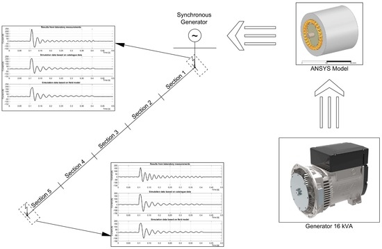
Field analysis is a useful tool for verifying the correctness of created peripheral models. In this thesis, the authors used the ANSYS Maxwell software in version 2019 R1 (ANSYS Inc., Canonsburg, PA, USA), which complements the concept of generator work modeling [
21,
22], with the calculation of synchronous generator parameters [
23] using the Matlab/Simulink package. Field analysis make it possible not only to model phenomena occurring in electric machines, but also to test selected generator structures before the changes are checked in the real object. According to the fact that the technical data provided in the specification did not contain enough information to enable a faithful reproduction of the analyzed generator in the ANSYS software, technical data were extended by the own dimensioning of the machine in order to reduce the inaccuracy of the field model.
Field analysis were carried out in the ANSYS Maxwell 2D and 3D simulation software for a 16-kVA salient pole synchronous generator. The generator model [
24] was created according to the geometric dimensions and electrical data contained in
Table 4 and is presented in
Figure 5. The created three-dimensional field model of the machine contained 331,743 mesh elements.
The
Table 5 summarizes the results of individual parameters of the tested generator based on the catalog data and results obtained from the field calculations.
where
Comparing the generator data provided by the manufacturer and the obtained values from the field model, it can be seen that they are similar, except for the direct axis subtransient reactance and quadrature reactance . Despite these differences, the results of field analysis based on limited construction data were considered sufficient to perform next simulations. In addition, measurements were carried out in the laboratory to determine the real direct axis subtransient reactance according to the low slip method. The value obtained was 1.68 Ω, and therefore its result is close to the value determined in the field analysis.
4. Results from Laboratory Measurements, Simulation Tests, and Analytical Calculations
With the usage of Matlab/Simulink program, the simulation model corresponding to the laboratory system was created. Based on the data declared by the manufacturer and those calculated from the field model in the ANSYS Maxwell software, the proper simulations were carried out. Additionally, for manufacture data, the short-circuit currents ware calculated based on the analytical Formulas (9)–(16) mentioned in second paragraph of the article (the results included in
Table 6). The obtained simulation results were compared with the real short-circuit current. The authors carried out a series of six measurements of the generator short-circuit current waveform, starting from the short-circuit occurring directly at the synchronous generator clamps, through short-circuits modeled after the first, second, third, and fourth section of the second-type line model (counting from the generator side), and ending with the disturbance occurring after the fifth section of the line.
The obtained waveforms were compared with the simulation results according to the catalog data, as well as with the simulation results in which the synchronous machine parameters (determined from field analysis) were used.
Figure 6 and
Figure 7 show a comparison of the obtained three-phase symmetrical short-circuit current waveforms for the selected generator phase.
The short-circuit current waveforms for the selected generator phase obtained from computer simulations, presented in
Figure 6, definitely differ from each other by the surge current values of the short-circuits. The surge current recorded using a laboratory model was 238 A, while for simulations using generator manufacturer data and simulations based on parameters obtained from field analysis, these values were 209 A and 183 A, respectively. The differences appeared due to the inaccuracy of the synchronous machine model used in the Matlab/Simulink software.
This inaccuracy consists in simplifications used in models that do not reflect all phenomena appearing in the generator in a short-circuit, as opposed to the physical laboratory system. Due to the asymmetrical rotor of the machine, a constant component existed for all fault current waveforms. For this reason, the steady-state short-circuit currents were given as peak-to-peak values. The peak-to-peak value for the real measurement was 20 A, for catalog data 16 A, and for calculations based on field results 17 A.
In the last measurement, presented in
Figure 7, the surge current value for the laboratory measurement and simulation based on the field model was the same and amounted to 161 A. For the simulation based on the manufacturer’s data, the surge value was 181 A. Partially, the difference follows that the value of γ
0 angle was not taken into account in case of the laboratory research. As expected, the steady-state short-circuit currents did not change.
Figure 8 shows the changes in the surge current value depending on the distance of the short-circuit location. The significant impact of each section impedance on the surge current is noticeable as opposed to the steady-state short-circuit current. These data are summarized in
Table 6.
S—section number (G—generator clamps),
LM—results from laboratory model,
CM—results based on catalog data,
FM—results based on field model.
AC—results from analytical calculations (based on catalog data).
For each modeled short-circuit, one can see a change in generator speed. As a result of the generator’s rotational speed decrease, the frequency in power supply network was reduced (
Figure 9).
As a result of a short-circuit, one can see a greater decrease in the generator rotor speed directly on the generator clamps than for a short-circuit after the fifth section of the line. This difference resulted from a higher short-circuit current, and thus the generator load moment (which was confirmed by the current values for the initial short-circuit states).
Figure 9 shows a reduction of more than 15% in generator speed, which was also associated with the same drop in the frequency of the supply voltage. In the case of a short-circuit after the line fifth section, the frequency decreased by approximately 7%. It should be underlined that, based on the analytical Formulas (1)–(16), the mentioned phenomena does not occur.
However, independent of the short-circuit location, the value of the short-circuit current was the same for both cases. This confirms that for this type of power sets, the line impedance has a negligible effect on the value of the steady short-circuit current. It significantly affected for the initial short-circuit current (for the analyzed cases, the initial current value changes from approximately 240 A to 160 A). This occurred because the values of attached sequentially impedances of each line section constituted approximately 20% of the value of the direct axis subtransient reactance
declared by the manufacturer. For a steady short-circuit, the impedance of one section was only 0.5% of the direct axis reactance
of the generator (
Figure 9).
Additionally, tests of the generator short-circuit process were carried out, including field forcing (
Figure 10). The value of the short-circuit surge current at the generator clamps was close to 270 A. However, a significant difference was visible in the waveforms for the steady-state of the short-circuit, because while using field forcing, the peak-to-peak value was 94 A. Therefore, in the case of properly selected field forcing control system for low-voltage synchronous generator, the achieved short-circuit current was equal about twice the generator rated current.
Due to the design of low-power synchronous generators, time constants values of electrodynamic processes (subtransient and transient) were very small. As a result, for each investigated case, a rapid disappearance of subtransient and transient components was visible. In the second period of the short-circuit, the current amplitude was already at 75 A. In the next one, it was about 50 A (
Figure 6 and
Figure 7) and still decreased, reaching the value of the steady-state short-circuit current. The protections used in electrical installations for this type of short-circuit current did not work quickly enough and did not disable the short-circuit within two to three periods, for which the current values were relatively large.
5. Conclusions
The short-circuit analysis of low-power synchronous generators presented in the article confirms the thesis of the significant problem of breaking the short-circuit by protections in low-voltage installations.
There are some manufactures recommendations of the generator set need to be take into account regarding the starting currents values of installed devices while choosing the generator power, which, in turn, prevents the full backup supply set use.
Currently, at the Cracow University of Technology, some researches are being conducted concerning the patenting of a new type of protection dedicated to the power sets, which allows for a quick power-off in the case of a short-circuit in a system powered by a low-power synchronous generator, even in the absence of the field forcing. As shown in the waveforms, as a result of the lack of field forcing, the steady short-circuit current has very small values for that currently used on a wide-scale protection, such as fuse switch-disconnectors and miniature circuit breakers, which do not allow the release of a given protection device. The work results on the test device will be disclosed after obtaining patent protection.
The developed field model allowed for an approximate analysis of short-circuit conditions. However, a significant difference in the values of waveforms for small short-circuit loop impedances was visible. It resulted from a much higher value of the subtransient reactance determined in the field model as compared with the catalog data. With full construction data (which the manufacturer does not disclose), it would be possible to create a more accurate model that would allow for more accurate analysis of the low-power generators dynamic states. However, it should be noted that the simulation results for catalog data also differ from the measured current waveforms. These differences are a consequence of numerical calculations and simplifications of the generator model itself implemented in Simulink. Also, in the analytical calculations, there were some differences in short-circuit current value as compared to the other research method. However, regardless of the assumed research method, despite of the impact on the peak values of the short-circuit current, the difference in overall energy carried by the short-circuit current was quite small. Therefore, the adoption of the most simplified research method did not affect the protections selection in electrical systems supplied by synchronous generators as backup energy sources. In turn, the fault location was notable in reference to short-circuit energy (Joule integral).
Nevertheless, the phenomena occurring in the generator for short-circuits are consistent with reality (subtransient, transient, and steady short-circuit). It is worth noticing that the results from laboratory measurements were carried out under more restrictive selection conditions of protective devices. The current values for the initial short-circuit state disappeared very quickly, resulting from short electromagnetic time constants, while the current for the steady-state short-circuit took values lower than the generator’s rated current.
The presented difference between the lack of field forcing and the use of this control method in short-circuit current waveforms leads to the conclusion that it is possible to turn off the circuit faster with a short-circuit by forcing because more energy is released. On the other hand, for all the presented short-circuit cases without the field forcing (unless it is switched off at the surge current), the steady-state short-circuit prevents the correct turn-off of the protected circuit due to the value of the current in this state, which is less than the rated current of the generator.
The short-circuit analysis presented in this paper has shown that due to the relatively low energy of the short-circuit currents in case of hybrid electrical systems, the generators of this systems require individual short-circuit protections. For this reason, while using these systems with the typical short-circuit protections, it is not possible to obtain selectivity of their operation, and their selection is complex.


