Article

A Novel Islanding Detection Technique for a Resilient Photovoltaic-Based Distributed Power Generation System Using a Tunable-Q Wavelet Transform and an Artificial Neural Network

by
S. Ananda Kumar
1,
M. S. P. Subathra
1,*,
Nallapaneni Manoj Kumar
2,*,
Maria Malvoni
3,*,
N. J. Sairamya
4,
S. Thomas George
5,
Easter S. Suviseshamuthu
6 and
Shauhrat S. Chopra
2,*
1
Department of Electrical and Electronics Engineering, School of Engineering and Technology, Karunya Institute of Technology and Sciences, Coimbatore 641114, Tamil Nadu, India
2
School of Energy and Environment, City University of Hong Kong, Hong Kong, China
3
School of Electrical and Computer Engineering, National Technical University of Athens, 15780 Athens, Greece
4
Department of Electronics and Communication Engineering, School of Engineering and Technology, Karunya Institute of Technology and Sciences, Coimbatore 641114, Tamil Nadu, India
5
Department of Biomedical Engineering, School of Engineering and Technology, Karunya Institute of Technology and Sciences, Coimbatore 641114, Tamil Nadu, India
6
Center for Mobility and Rehabilitation Engineering Research, Kessler Foundation, West Orange, NJ 07052, USA
*
Authors to whom correspondence should be addressed.
Energies 2020, 13(16), 4238; https://doi.org/10.3390/en13164238
Submission received: 30 June 2020 / Revised: 7 August 2020 / Accepted: 10 August 2020 / Published: 16 August 2020
(This article belongs to the Special Issue Assessment of Photovoltaic-Battery Systems)

Abstract

:
Finding an appropriate technique to detect an islanding issue is one of the major challenges associated with the design of a resilient grid-linked photovoltaic-based distributed power generation (PV-DPG) system. In general, the technique used for islanding detection must be able to sense the disruptions from the electric grid and quickly disconnect PV-DPG from the grid. The quick disconnection of PV-DPG mostly avoids power quality problems, damage to power assets, voltage stability issues, and frequency instability. In this paper, a new islanding detection technique that is based on tunable Q-factor wavelet transform (TQWT) and an artificial neural network (ANN) is proposed for PV-DPG. The proposed approach consists of two steps: in the first step, the vital detection parameters are computed by performing simulations considering all possible switching transients, islanding events, and faults from the grid side. Then, the decomposition of obtained signals is done using TQWT on different levels. Using the obtained coefficients, at each level, features such as range, minimum, mean, standard deviation, maximum, energy, and log energy entropy are computed. The optimal feature set was selected as the input for the second step. The classification of the non-islanding and islanding states for PV-DPG is made using the ANN classifier in the second step, which achieved an accuracy of 98%. The results representing the efficiency of the proposed approach in noisy and non-noisy environments are also explained. Overall, it is understood that the proposed islanding detection technique would provide suitable insights to detect an islanding issue.

Graphical Abstract

1. Introduction

Globally, there has been an increasing and ongoing transition towards renewable energy resources (RERs) for power generation for several years. As of 2018, the global energy generation through RERs was over 26%, and by the end of 2019, renewable energy installations expanded by 7.6% [1,2]. With the help of these RERs, on-site energy generation is possible that is generally referred to as the distributed power generation (DPG). A standard DPG is characterized by power generation based on RERs such as solar, wind, hydro, hydrogen fuel cells, and power storage through various battery systems. In some cases, multiple RERs-based power generation facilities called microgrids are linked and are referred to as hybrid RERs-based microgrids [3]. The use of electricity from such DPG is commercially and socially favorable in some cases for the prosumers [3,4]. In some cases, depending upon the benefits provided by the electric utility in terms of power selling and, incentives for supplied power during peak hours, favorable selling prices etc., the DPG systems are linked to the electric power grid, which has led to considerable progress in DPG-linked electrical power grids in different countries.
DPG that are interconnected with the grid may be affected by islanding issue due to grid disturbances, and identifying these will be a challenging task. Islanding is a process where the grid is removed from the network, and the entire load is directed to the DPG system that is still connected [5,6]. So, it is essential to detect these islanding events and respond in time for a resilient DPG. Otherwise, the islanding issues will pose many unavoidable problems that include, power quality, voltage stability, energy loss, and damage the power assets [6]. In some cases, due to grid or load side disturbances, the electrical lines might fall, which needs immediate reconstruction. During this time, there exists a risk for the utility staff, if they do not recognize fallen lines during reconstruction. This proves that, in DPG-based microgrids, there exist several risks, making us realize and think of engineering microgrids from a resilience point of view and it can be done in many ways. Indeed, there are numerous ways to understand resilience, for example, in recent studies, network analysis is employed to understand the resilience and sustainability of industrial symbiosis system that facilitates energy, water and material flows [7,8]. The same network approach is further extended and applied in few critical infrastructures like energy resources and power sector, information technology and communication, finance, healthcare and public health, transportation, and food and agriculture for understanding the implications of interconnectedness and interdependencies on resilience [9,10].
Recent studies, for this reason, have called for engineering greater resilience in microgrids [11,12]. This study explicitly addresses the resilience of DPG in the context of islanding. Infrastructure resilience is composed of four phases: first, the systems preparedness to evade disruptions; second, their ability to withstand and absorb impacts of inevitable disturbances; third, the capacity to recover and respond; and fourth, the capability to learn and adapt [13,14,15]. Using this four phases approach, a previous study on power resilience enhancement of PV based DPG for the New York location [15] has been carried out. Based on their resilience assessment, they suggested the development of effective grid disturbance detection techniques as a critical area for research. Our study is focused on improving the resilience of DPG through early detection of islanding and allowing local facilities to respond very quickly.
There exist a few standards that may address the islanding issue, for example, the IEEE 1547.4 that mainly focuses on the functioning of local facilities considering the engineering aspects [16]. As per the IEEE 1547.4, the solution to “electrical islanding,” is simply to provide power when utility power is not available [16,17]. Here, the islanding time is generally less than 2 s, so the detection should be made very quickly, which means there is a need to apply appropriate techniques that allow prompt strategic actions. The islanding detection techniques are classified under two broad categories, remote and local approaches. The techniques of remote islanding detection (RID) are mainly focused on some kind of communications between the electric power grid and DPG. Under the RID category, two different schemes are used those include the transfer trip and power line carrier communication (PLCC) schemes [17,18,19,20]. The RID method is more effective than local methods but is more expensive when using dispersed power generators in the electric power supply system [18,19,20,21]. The other category is the local islanding detection (LID); here the determination of unit parameters is given a priority, and they mostly rely on applied LID techniques. These units parameters include voltage, current, frequency, impedance, active power, and reactive power on the DPG, i.e., the power converter side (inverter) [22]. Such approaches are often graded into passive, active, and hybrid techniques [18]. Typical connection levels, harmonic distortion at the DPG location, are regulated by passive techniques for the interface parameters voltage, current, and frequency [19]. Here, the thresholds may be paralogism and null, and are typically set experimentally. The lower threshold setting can cause a disturbance and isolates in higher thresholds cannot be identified [20]. Recently, active strategies were being used and implemented for islanding detection considering the minor grid disturbances [21]. An active islanding detection scheme is also proposed in the literature for active power and reactive power control loops of the synchronous DPG [22,23]. Timely detection of the islanding situation is guaranteed using these schemes for both static load and motor load, even when there is an exact match between generation and load demand. The passive technique is primarily utilized during islanding issues identification, and the active techniques are secondary, and the combination of these approaches improves many efficiency indexes [20,21]. The hybrid techniques mainly operate on the combined characteristics of the methods mentioned above and are easily applicable to complex structures [24].
The drawback of large non-detection zones and threshold setting requirement associated with the above-mentioned islanding detection method is handled by employing signal processing and intelligent classification (SP&IC) techniques [25,26,27,28,29,30,31]. Techniques of SP&IC are typically used to boost the efficiency of passive islanding detection approaches. The methods for signal processing mostly assist researchers in separating the features for islanding detection from the calculated signals [26,27]. There exist numerous signal processing techniques, but the most used techniques for islanding detection are the Fourier transform, Wavelet transform, s-transform, tt-transform, and Hilbert–Huang transform [28,29,30,31]. In the wavelet transform, the energy coefficients are extracted as vectors for wavelet transformation (WT) in various frequency bands in the transient voltage signal phasing process to identify islanding incidents [26,31]. The findings indicate that traditional wavelet processing under noisy conditions was replaced with stage space. The phasing space approach can also be used to derive possible vectors from 3-phase DPG terminal power signaling systems and equate output and traditional wavelets. However, the method suggested contributed to heavy computation pressures and volume specifications. However, recently in photovoltaic based DPG (PV-DPG) networks, techniques such as hybrid WT and multi-resolution spectroscopy along with a deep learning approach were applied [30,31]. Another method of islanding sensing is the implementation of an adaptive neuro-fuzzy inference device (ANFIS) and a discrete WT [32]. This study is based on the modern approach named Hilbert–Huang Transform (HHT) that is used to the study of the islanding. It is a time-frequency method, along with empirical mode decomposition, which makes it suitable for islanding detection; therefore, HHT is a very efficient approach for the removal and detection of islanding characteristics [33]. An islanding detection method based on the combination of a wavelet packet transform (WPT) and a probabilistic neural network (PNN) was presented [34]. The voltage obtained at the point of common coupling (PCC) is measured and decomposed by the WPT. Normalized Shannon entropy (NSE) and the normalized logarithmic energy entropy (NLEE) feature vectors are obtained from the WPT coefficients and finally fed to the PNN classifier to classify the disturbances. Discrete wavelet transforms with multi-resolution singular spectrum entropy are utilized to extract the unique features of three-phase voltage signals at the PCC. The extracted features are fed to support vector machines to detect and classify different types of faults in a PV-DPG system [35]. In another study, for islanding, detection, Slantlet transform (SLT) is used, where the characteristics of all potential detection signals are considered in the signal processing tool. Here, for preventing the selection of thresholds, the Ridge-based Probabilistic Neural Network (RPNN) method is suggested. The RPNN prevents the threshold selection by means of advanced training because the behavior features in the hidden model layer of the neural network can be used to distinguish islanding and non-islanding [36]. In another study, a novel phaselet algorithm-based signal processing technique is used to detect the islanding phenomenon in DPG [37]. The phaselet algorithm is versatile and is based on the effective computing capacity of the inverter-based distributed power generation (Inv-DPG). The phaselet algorithm is effective when compared to other traditional methods used for DPG [37]. In recent studies focused on feature extractions, the modified and hybrid approaches are applied. One such new feature extraction tool is proposed in the literature is the modified SLT, which is based on the harmony search algorithm (HSA). HSA uses this technique to determine the most acceptable degree of degradation and an optimum number of transformative Slantlets needed to detect the islanding. Here also, the RPNN and Vector Machine Approaches (VMA) are used to prevent thresholds from being chosen [38]. From the above literature review, it is understood that different SP&IC techniques are being applied to further improve islanding detection in PV-DPGs.
In this paper, a new islanding detection technique that is based on tunable Q-factor wavelet transform (TQWT) and an artificial neural network (ANN) is proposed for a photovoltaic-based distributed power generation (PV-DPG) system. The considered DPG system is the 3-phase grid interconnected photovoltaics (PV). The proposed ANN-based-TQWT could be one of the better techniques for islanding detection as it provide better practical estimations. Here, all sensing signs, including voltage, voltage change rate, the dc-link voltage, d-q axis voltage, frequency, and the frequency change rate, are tested for any device failures. Besides, the intermittent changes and PV-DPG islanding situations are also considered. The proposed technique is executed in two steps: The first step is the simulation and calculation of all the possible switching transients, islanding events, and electric power grid failures. Using TQWT, the signals obtained are decomposed to several stages, and features like the standard deviation, maximum, range, minimum, mean, energy, and log energy entropy characteristics are determined from their respective coefficients preferred from 1 to 20. Seven separate features were gathered from the obtained sub-bands. The Kruskal–Wallis test is performed on the computed features, and the features with a p-value less than 0.05 are selected as optimal features. In the second step, the selected optimal features are then fed into the ANN classifier for classifying the non-islanding and islanding states of PV-DPG.
Overall, in summary, the key contributions of this study are described as follows:
  • TQWT signal processing technique is used to extract features from all available detector signals for islanding detection.
  • Threshold selection through the ANN model, which is based on conjugate gradient algorithms to classify islanding from other grid-disturbance.
The paper is structured in five sections; Section 2 provides the tested system configuration. In Section 3, the proposed ANN-based TQWT islanding detection technique is described. The obtained results for the PV-DPG, along with discussions, are presented in Section 4. Lastly, in Section 5, conclusions are drawn.

2. Configuration of Photovoltaic-Based Distributed Power Generation System

In this paper, an efficient islanding detection technique for a photovoltaic-based distributed power generation (PV-DPG) system is proposed. For investigating the applicability of the proposed islanding technique, a 3-phase grid-connected PV with the inverter system that is used in ref [36] is considered and is shown in Figure 1.
In the PV-DPG, the PV array configuration is achieved by series and parallel connection of PV modules. The modeled PV array has 86 parallel strings, and each string has 7 PV modules that are connected in series. Apart from the PV array, in PV-DPG system there exists few other assets. These assets include the maximum power point tracking (MPPT) equipment, a 2-phase DC/AC conversion network consisting of 3-level pulse width modulation (PWM) signal fed Insulated Gate Bipolar Transistor (IGBT) bridge. At the IGBT, harmonics are possible, and these were filtered using small harmonic filter C and the inverters choke resistor–inductor (RL). Transformer is one other asset that is used to in the proposed system [36]. Here, the output of a 3-phase inverter is fed to the electric power grid using the transformer.
The assets of this PV-DPG system are provided in Table 1. Considering all these assets listed in Table 1, the system is modeled, simulated, and then analyzed using MATLAB/Simulink tool 2019a.
In the PV system, solar irradiance is the primary parameter that is responsible for power generation. Apart from irradiance, the PV array output parameters will also depend on temperature; hence, while simulating the PV array model, the input irradiance and operating temperature are considered as 1000 w/m2 and 45 °C respectively. With the irradiance and temperature as inputs, the operating behavior of the PV array is observed, which is almost in line with the manufacturer’s predicted outputs. Approximately, at t = 0.15 s, PV array output parameters are found; those include the voltage (i.e., 481 V) and the power (i.e., 236 kW). In later steps of simulation, the PV behavior is observed to change concerning the changes in input parameters. To understand this clearly, at approximately t = 0.3 s, the irradiance input to the PV array model is lowered to 200 w/m2. Accordingly, the observed reference voltage (i.e., Vdc) is changed to 464 V. The observed variations in the electrical parameters are shown in Figure 2, Figure 3 and Figure 4, respectively.

3. Tunable Q-Factor Wavelet Transform and ANN-Based Islanding Detection Technique

TQWT is one of the wavelet transform techniques widely used in numerous applications. It comes under the discrete-time wavelets approach with constant input parameters implicitly tunable. In TQWT, three tunable parameters are possible, and these include the Q-factor (Q), absolute redundancy (r), and decomposition stage number (j). TQWT is useful for changing the tunable control parameters to the oscillating actions of the control signal [39]. The Q-factor is commonly known as the middle frequency/bandwidth ratio, and it regulates the swing within the wavelet as Q is inversely proportional to the center frequency bandwidth [40]. Based on the Q-factor, the frequency resolution is regulated. The frequency resolution is enhanced for the high value of Q. Besides, a small Q-factor wavelet is useful for smooth signal processing [41]. Here, the ratio of the total number of wavelets to the input signal frequency gives the r parameter, and it can be used to calculate the transform over-sample rate [39]. However, to have a clear understanding of the frequencies in sub-bands, especially at different stages of j level decomposition, a general framework support is taken. Indeed, the number of j banks with two-channel filters is cascaded to fall at j level.
The TQWT is designed with a filter bench with two-channel drains that include low pass and high pass. The support of low-pass and high-pass filters (LPF and HPF) along with low-pass and high-pass scalable components are considered here. The two low-pass channels are formed by LPF, and the high-pass channels are formed by HPF [42,43]. The signal is continuously distributed as a reference to both low and high-pass networks. Then the low-pass stream is given as an entry to a filter bench for the next two channels. It implies the j numbers are linked to two-channel filter banks. The high-pass channel performance of a two-channel filter bench is a sub-band in this relation. A sub-band is also created by the low-channel of the last two-channel filter. Therefore, in the frequency response of TQWT, there are sub-bands of j + 1 [44]. The signal frequency converts, with a sampling rate f s resulting in α f s and β f s , sampling frequencies the input signal s[n] into a low-pass and high-pass sub-band signals. The process of decomposition and reconstruction using TQWT is shown in Figure 5.
The mathematical representation for LFP and HPF, (i.e., H 0 ( w ) and H 1 ( w ) ) are described below in Equations (1) and (2) [45]:
H 0 j ( ω )   =   { π m   =   0 j 1 H 0 ( ω α m ) ,       | ω | α j π     0 ,               α j π | ω | π
H 1 j ( ω )   =   { H 1 ( ω α j 1 ) π m   =   0 j 2 H 0 ( ω α m ) ,     ( 1 β ) α j 1 π | ω | α j 1 π 0 ,                               f o r   o t h e r s   ω     [ π ,   π ] .  
The redundancy and Q parameters can be expressed in the TQWT with the α, and β scaling parameters are represented in Equation (3) [45]:
r   =   β 1 α ;   Q   =   2 β β
In Figure 6, the TQWT block diagram is explained in a detailed manner. In this study, the TQWT technique is applied for islanding detection in renewable-based DPG applications based on the available theoretical and practical knowledge.
The proposed TWQT based islanding detection technique is applied for a three-phase grid-connected photovoltaic (PV) inverter system and is simulated using MATLAB/Simulink tool 2019a. The input signals are simulated for various islanding and non-islanding signals, as depicted in Table 2.
The first two cases (i.e., C1 and C2) are the islanding cases and rest four (i.e., C3, C4, C5, and C6) are non-islanding cases [36]. They are labeled as C1 to C6, respectively and given below:
  • In the first islanding case (i.e., C1), 80 tests were done with signals having different loads that match with distributed power generation.
  • In the second islanding case (i.e., C2), the simulation is done considering 120 tests having signals with different loads greater or lesser than distributed generators.
  • The third case (i.e., C3) with induction motor starting has variations from 5 HP to 215 HP power.
  • The fourth (i.e., C4) is also a non-islanding one that mainly focuses on and discusses the capacitive switching.
  • The fifth case (i.e., C5) enumerates the switching of various loads.
  • The sixth non-islanding case (i.e., C6) is simulated with various faults like the single line to ground fault, double line to ground fault, a line-to-line fault case.
The proposed TQWLT technique is used to decompose the islanding and non-islanding signals. Here, the three tunable parameters of the TQWT like Q-factor (Q), absolute redundancy (r), and decomposition stage number (j) are used. Here, the application of TQWT was very much useful, and this is because of the benefits observed in changing the tunable control parameters to the oscillating actions of the input control signal. As mentioned earlier, here also the preprocessing is done using LPF and HPF. The proposed approach consists of two steps: firstly, all possible switching transients, islanding events, and grid faults are simulated, and the vital detection parameters are computed. By using TQWT, the obtained signals are decomposed into different levels, and the features such as range, minimum, mean, standard deviation, maximum, energy, and log energy entropy are computed from coefficients at each level. The optimal feature set was selected as the input for the second step. Secondly, the ANN classifier is used to classify the non-islanding and islanding states. The best features were selected through the Kruskal–Wallis test. Then for the classification of islanding and non-islanding cases, ANN with a conjugate gradient algorithm was used and classified.

3.1. Feature Extraction

The unique characteristics that can be used to classify the islanding and other grid disturbance cases can be determined using the efficient feature extraction method. Here, the selected signals are listed in Table 3, along with a brief description. For the selected signals, the TQWT method is applied and decomposed into different levels depending on the value of Q, r, and j. From each coefficient, the features mentioned in Table 4 are extracted. In this work, various levels are changed to select a suitable scale for distinguishing the islanding and the non-islanding cases. Thus, for j levels, (j + 1)*7 feature vectors are computed. To select the optimal features, the Kruskal–Wallis test is done. The features with the p-value < 0.05 are chosen as the best features and fed into the ANN for classification.

3.2. ANN Classifier for Islanding and the Non-Islanding States

The ANN learns via the detecting patterns as well as relationships in data and through experience [46]. The neuron is the basic computer that calculates a number of inputs and results with an activator function. If the neuron shoots, the output will be the input of another neuron, producing a complex network based on the phase of training. The process of neuron firing can be defined mathematically based on the activation function (f), as shown in Equation (4).
Y ( t )   =   f ( i   =   1 n ( X i ( t ) W i ( t )   +   b ) )
where t represents the time, b is the bias, and at time t, the Y ( t ) , X i ( t ) , and W i ( t ) are represented as outputs, input, and neural input weight, respectively.
The weights of the neurons are adjusted by the back-propagation during training [47,48]. The ANN has gained popularity for prediction in electrical load forecasting and classifiers in islanding detection techniques. Hence, ANN is employed in the proposed work. After rigorous training under different experimental conditions, the conjugate gradient with Powell–Beale restarts the back-propagation algorithm selected for the proposed approach, and the used parameters are shown in Table 5.
The structure of an ANN used for islanding detection is represented using three different layers. These include an input layer with 7 neurons, the output layer, and a hidden layer. Each layer has neurons; their count is varied. In the hidden layer, neuron count mainly depends on the number of input features, the number of hidden neurons is selected to be 40, and the neurons in the output layer are 2. The ANN architecture with a sample of seven input features, 40 hidden neurons, and 2 output neurons is depicted in Figure 7.
Classification performance based on overall classification accuracy is calculated using the mathematical expression given in Equation (5) [45,49]
Accuracy   ( % )   =   TP   +   TN TP   +   TN   +   FP   +   FN   100
where TP = True Positives, TN = True Negatives, FP = False Positives, and FN = False Negatives.

4. Results and Discussion

Using the approach shown in Figure 8, the simulation is carried out, and results are analyzed for nearly 400 separate islanding and other grid disturbances. The main motto for analyzing 400 events is to measure and test the suggested procedure, i.e., ANN-based TQWT. Among the 400 events, 200 are the islanding cases, and the other 200 are the grid disturbance activities (non-islanding events). The 200 islanding events were created for different combinations of active and reactive power mismatches in simulation cases C1 and C2. In comparison, the other 200 non-islanding events were generated by the multiple switching steps, which may contribute to the disturbances related to faults, safety concerns, and relaying issues. These 200 non-islanding events were simulated under the cases C3, C4, C5, and C6.
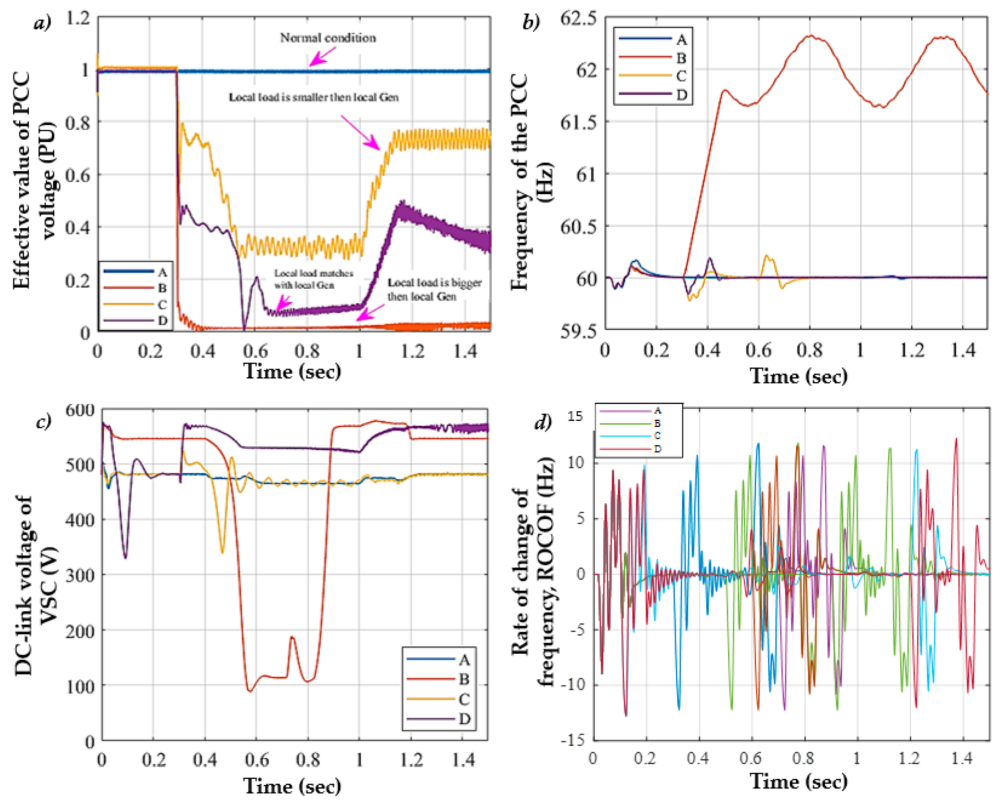
In the simulation case C1, the state of islanding took place at t = 0.3 s. Accordingly, the changes have been observed in various electrical parameters. Figure 9 demonstrates the parameters at the point of common coupling, and these include the effective value of voltage, frequency, DC-link voltage of voltage source control, and the rate of change of frequency (ROCOF). The obtained results are for the photovoltaic based distributed power generation (PV-DPG) under different isolation scenarios. The worst-case was where power consumption was associated with the local PV inverter energy output, which is the most complicated circumstance where islanding incidents are observed.
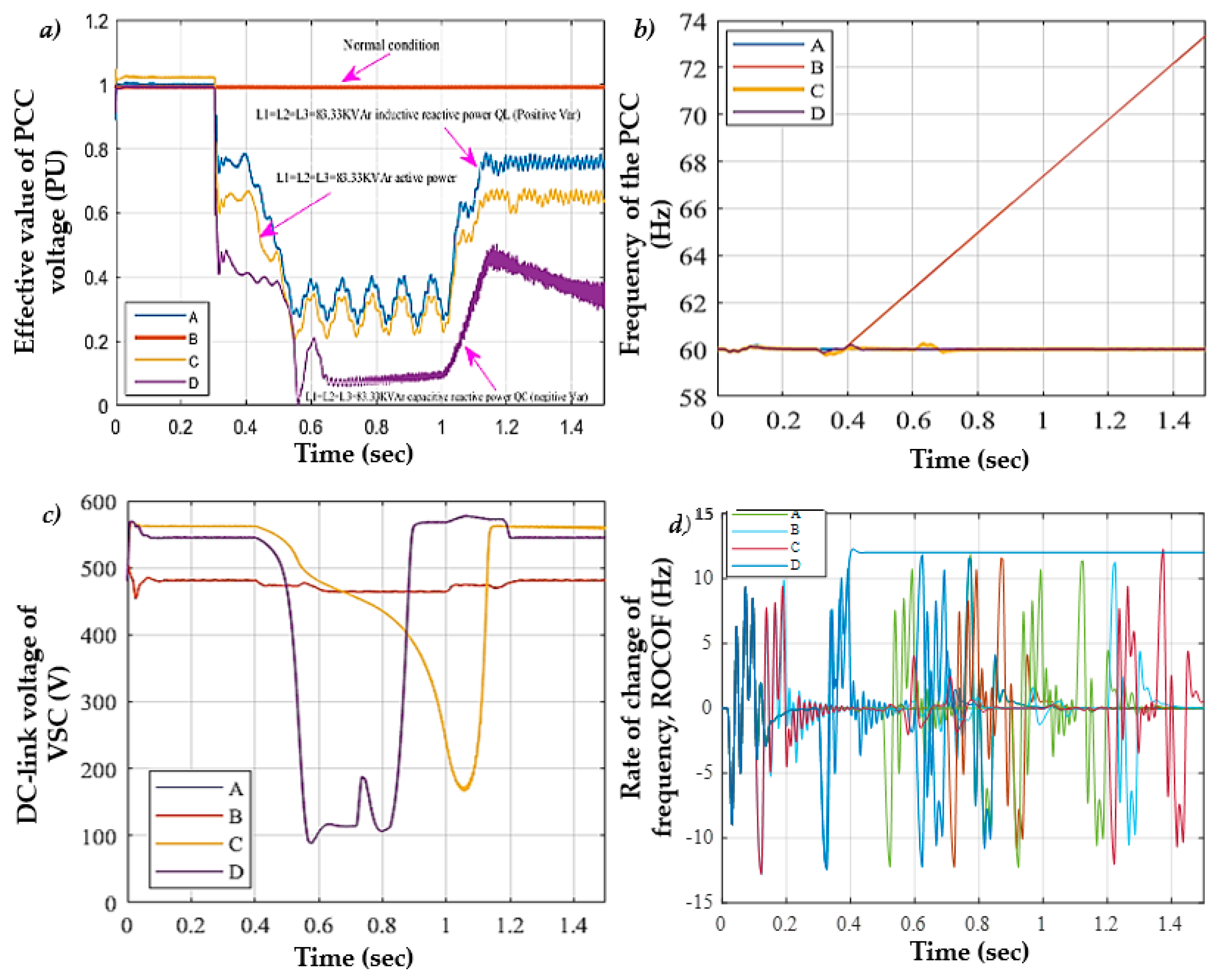
In the simulation case, C2 also, the state of islanding, took place at t = 0.3 s. Here, the different combinations of active and reactive power mismatches are observed. As per the given islanding events for the C2 case, the changes have been found in various electrical parameters, see in Figure 10.
From Figure 10, the changes in the parameters that include the effective value of voltage, frequency, DC-link voltage of voltage source control, and the rate of change of frequency at the point of common coupling when local power load matches with local power generation are presented.
From the observed results, it is seen that the voltage of the inductive reactive loads is almost very close to the dc-link voltage of voltage source control of reference loads. For capacitive reactive loads, PV inverter loses the control of frequency, so islanding condition was more difficult to recognize for other loads.
In the simulation case C3, the induction motor was introduced at t = 0.3 s, beginning from specific capacities ranging from 5 to 215 HP. The observed variations when a motor switching value has been changed for local load are presented in Figure 11. The displayed electrical parameters at the point of common coupling include effective voltage, the changing frequency, the DC-link voltage of the voltage source control, and the rate of change of frequency.
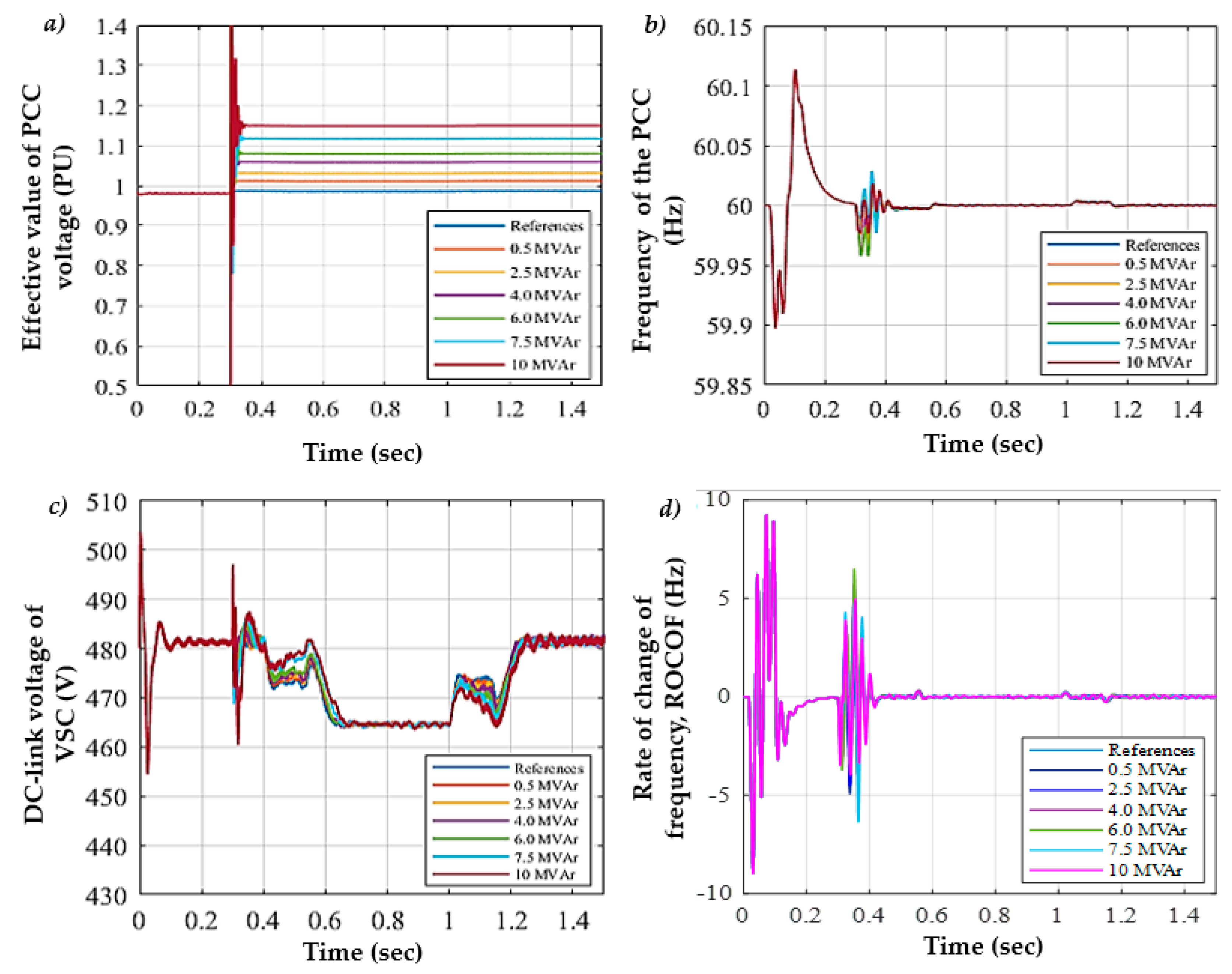
In the simulation case C4, switching the capacitor bank at various places in the PV-DPG system is introduced, and the value was beginning from specific capacities ranging from 0.5 to 10 MVAr. Once the introduced capacitor bank has turned on at t = 0.3 s variations in the electrical parameters are observed, which include the effective voltage, frequency, and DC-link voltage at the voltage source control and rate of change of frequency, see in Figure 12.
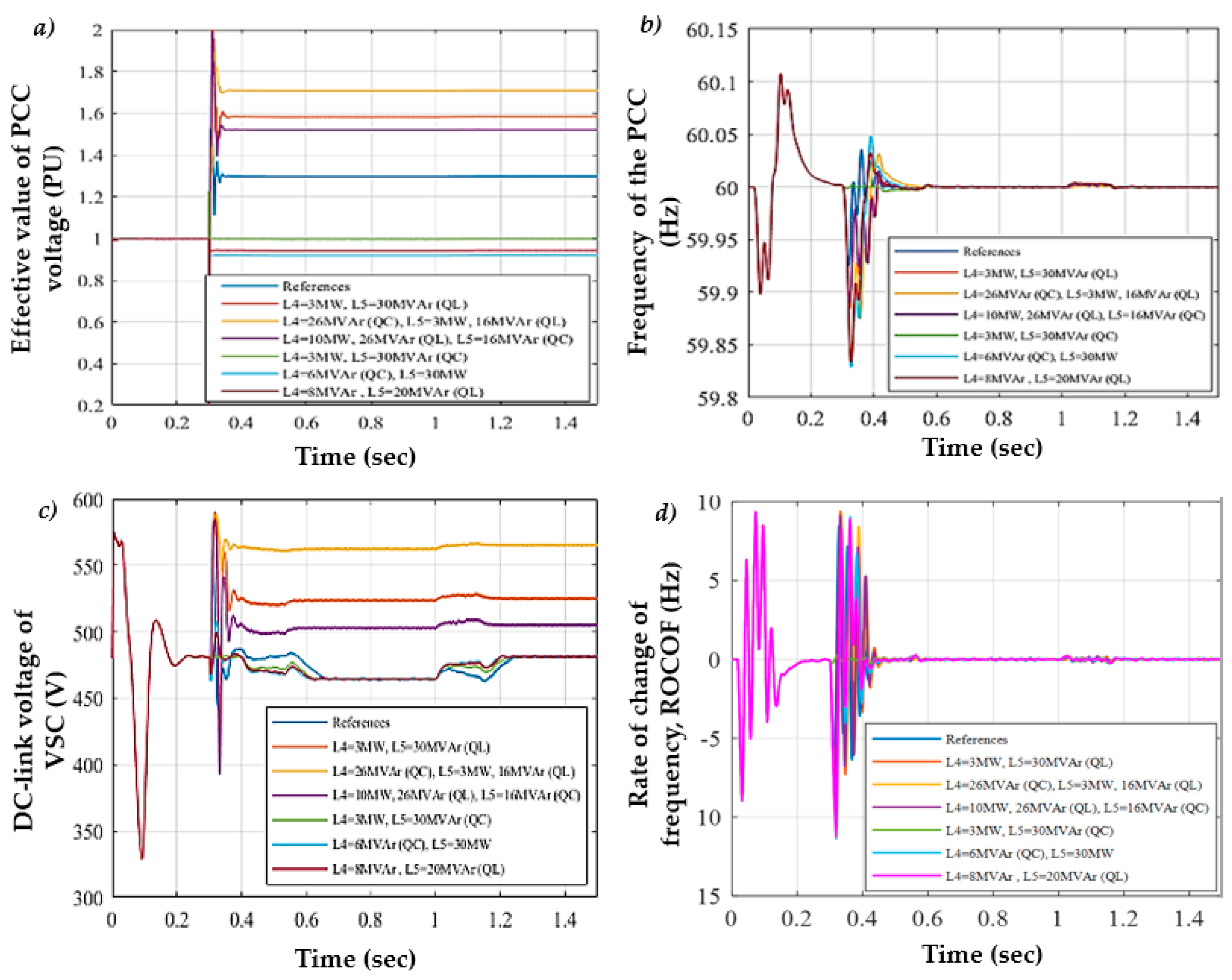
In the simulation case C5, at t = 0.3 s, various linear and non-linear loads were introduced. This typically means that the switching on/off of the loads for non-islanding events has taken place. The observations under the load changing conditions are depicted in Figure 13, and they include the effective value of point of common coupling voltage, frequency fluctuations, DC-link voltage of voltage source control, and rate of change of frequency in the conditions of change of load.
In the simulation case C6, different fault occurrences were considered. Here, single, double, and 3-phase failure events were introduced at t = 0.3 s at various places that are bit away from the point of common coupling (near and far away from the point of common coupling). The position of the contact points for three-phase loads is 8 and 14 kilometers from the point of common coupling.
Overall, 140 fault events were applied whose resistance value range between 0–200 ohm, and they are cleared after 150 ms. Accordingly, the changes have been observed in various electrical parameters. Figure 14 demonstrates the parameters, and these include the effective value of voltage, frequency, DC-link voltage of voltage source control, and the rate of change of frequency (ROCOF). From Figure 14, it is understood that the values for voltage source controls the dc-link voltage and frequency differed considerably when the resistance of fault event is 200 ohm. At this point, the voltage scale was decreased by 2%. Therefore, it became more complicated to assess the islanding situation from non-islanding. In addition to the change in voltage, it is also understood that the change in frequency is considerable.

4.1. Performance Metrics

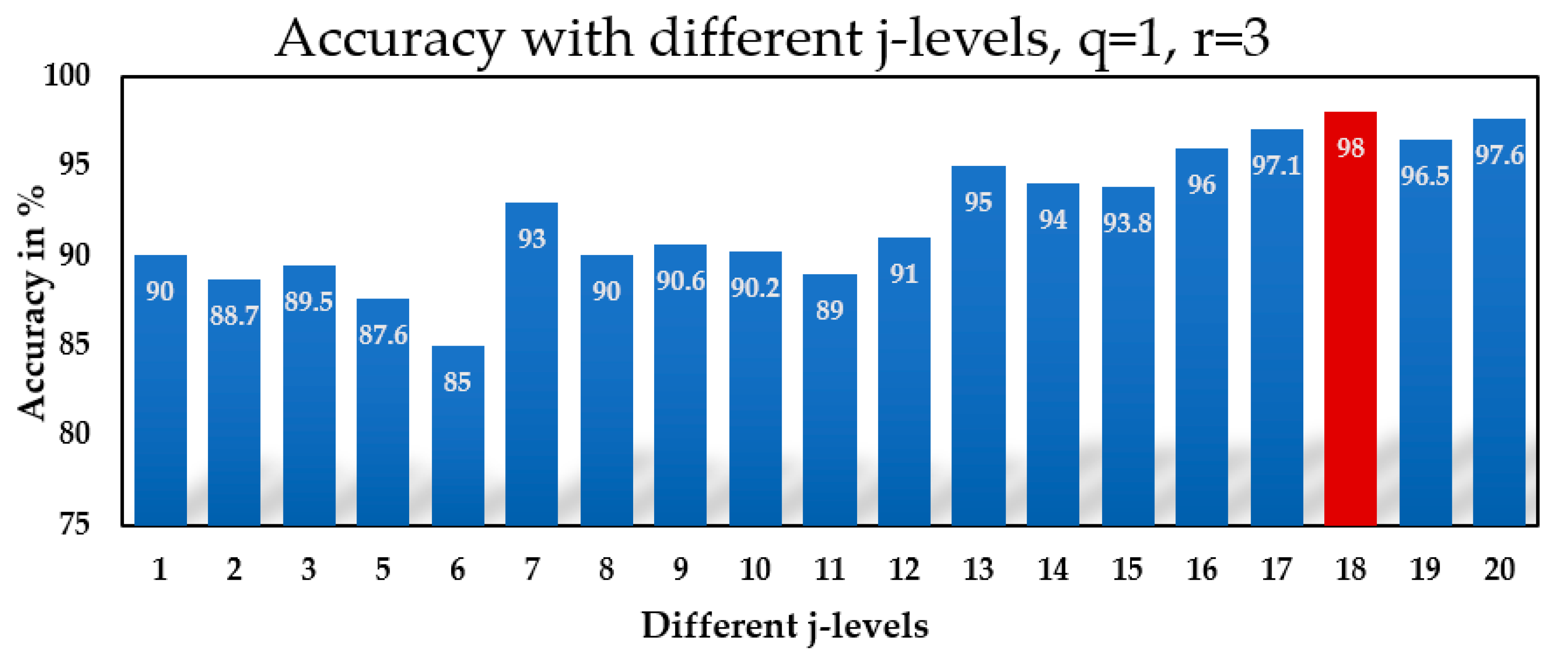
These are the samples for PCC voltage, frequency, frequency change, voltage change rate, VSC (voltage source control) dc-link voltage, which is chosen as the basis of the above procedure in multiple islanding and non-islanding situations, and the islanding detection relay classification pattern. The total number of samples considered is 200 islanding and 200 non-islanding. This can be seen; in islanding cases, the value of this index was not related to other non-islanding events. Several experiments are conducted to select the optimum values of Q and j. The minimum value suggested for r is 3, and it can be increased. However, the r increase increases the overlap in the neighboring frequency response; hence, in this work, the r-value was fixed to be 3. The best value for the parameter Q and j is to choose. The minimum value of Q is fixed to be 1, and the j value was varied from 1 to 20. Seven characteristics of the collected substrates have been extracted. The Kruskal–Wallis test is performed on the computed features, and the features with a p-value less than 0.05 are selected as optimal features. The selected characteristics are fed into an Artificial Neural Network for classification. According to the classification accuracy, the best j value is selected. The bar plot representing the classification accuracy for different levels is displayed in Figure 15. Level 18 was achieved with a maximum accuracy of 98%.
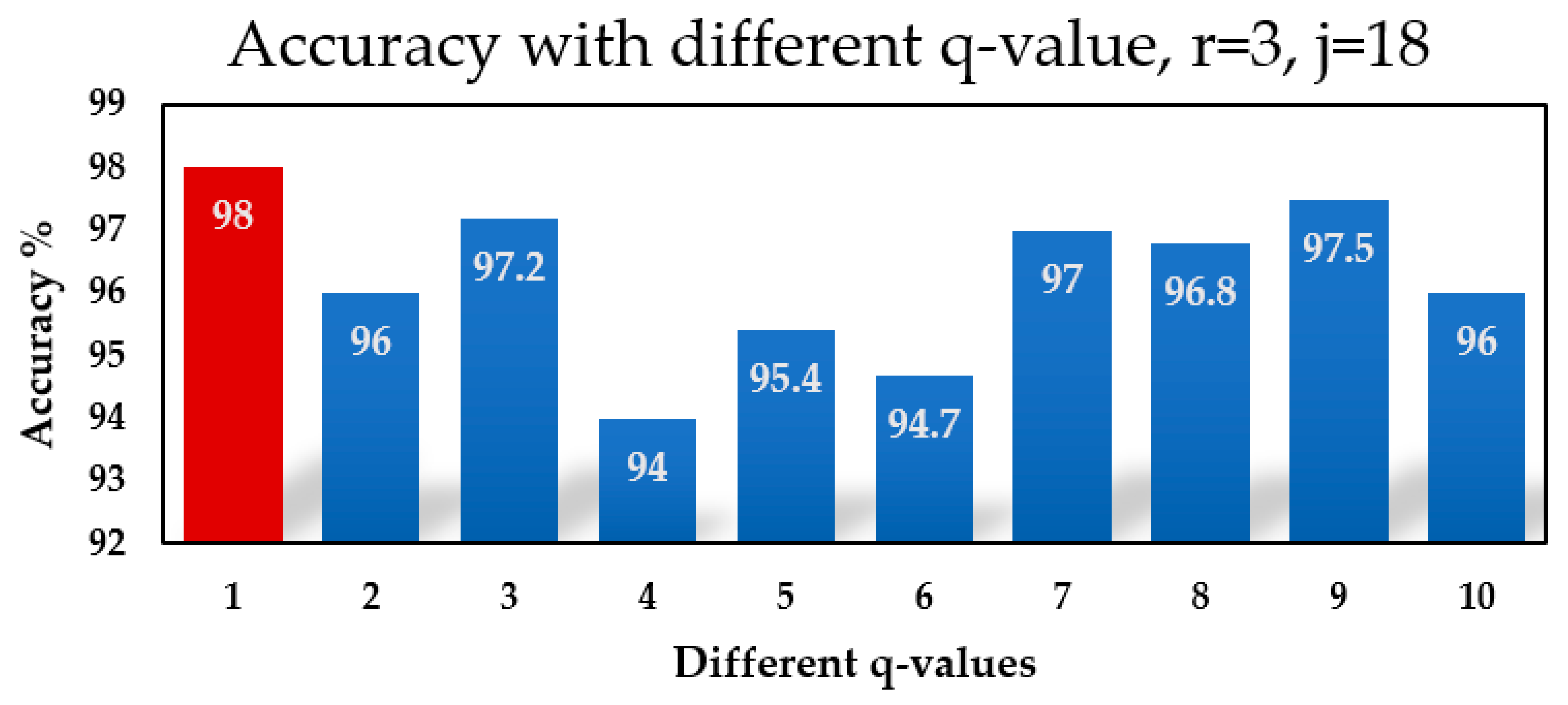
Hence, for further experimental conditions, the j value is fixed to be 18, and the q value varies around 1 and 10. The classification accuracy versus the Q value is shown in Figure 16; the Q value with 1 attained the maximum accuracy.
Thus, in this work, using the procedure mentioned above, the Q value is selected as 1, and the j value is selected as 18, with the r value as 3. The seven different features are extracted from 19 sub-bands (j + 1); hence a total feature vector length of 133 was obtained. Through the Kruskal–Wallis test, the best features are selected for classification.

4.2. The Output of the Training Methodology under Ideal and Noisy Condition

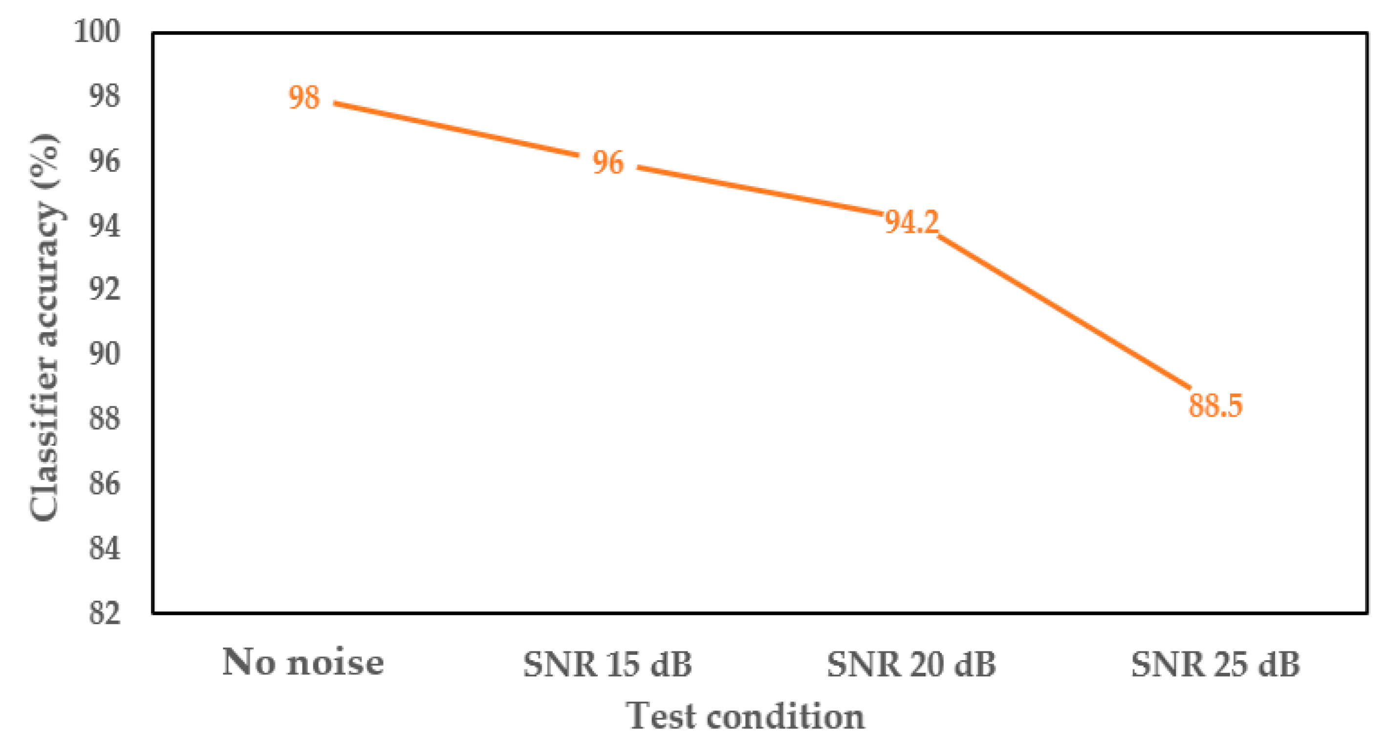
The performance of the classifications of the ANN-based island detection procedure is shown in Figure 17 in ideal circumstances and noisy environments. The data collection is divided into the following categories of incidents, such as the case islanding events (C1, C2), load, capacitor, and motor switching for the cases (C3, C4, C5,) along with fault events in (C6), to assess the classification efficiency of the proposed solution in depth. Thus, the classification performance for each event can be evaluated separately. In order to establish the noisy condition, additive white Gaussian noise (AWGN) is used uniformly and signal to noises ratios (SNR) of 15 dB, 20 dB, and 25 dB on to both islanding and other grid-distribution signals.
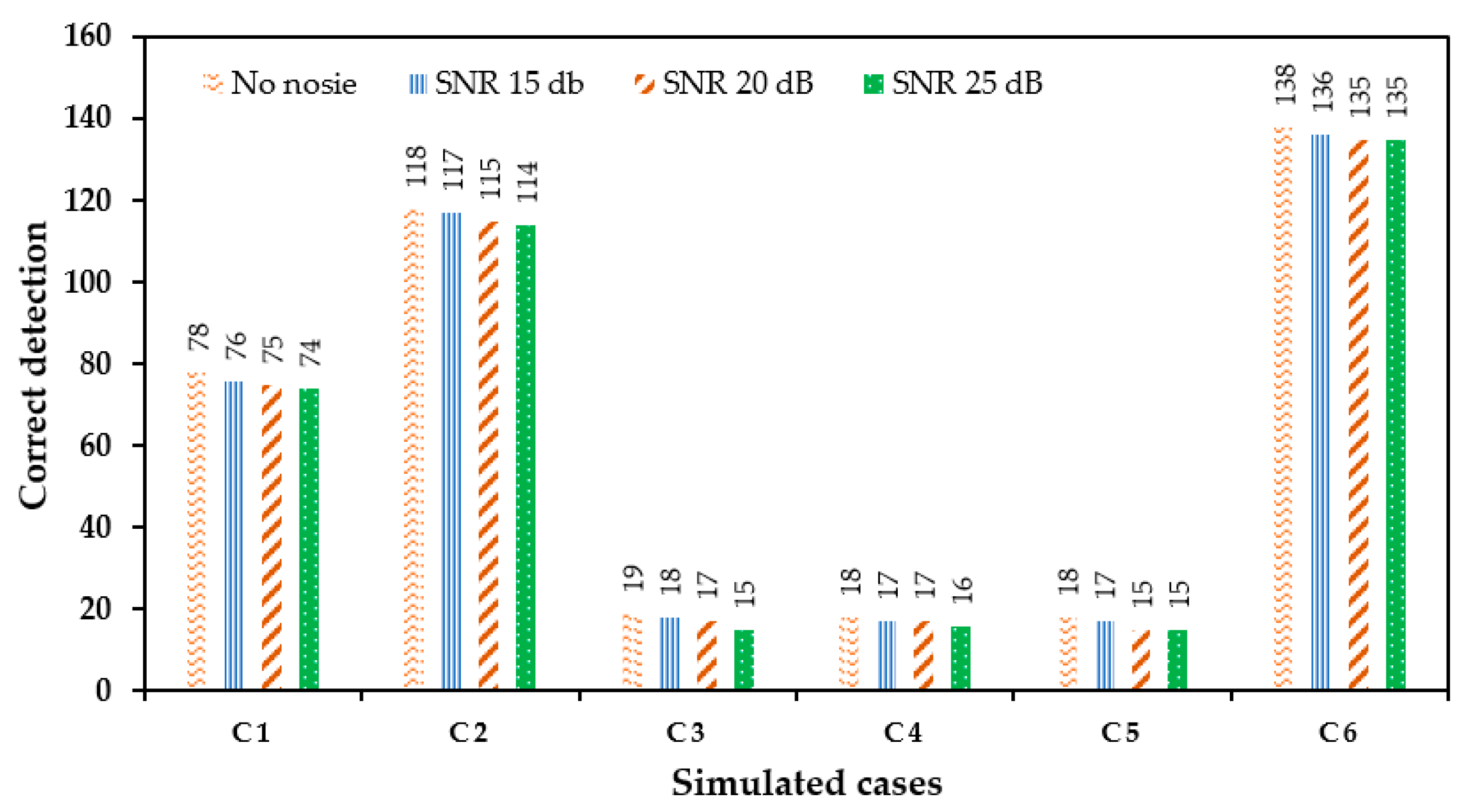
From Figure 17 it is clear that the classification performance of TQWT with the ANN method under no-noise conditions attained the highest classification performance, while the classification accuracy of noisy conditions is between 88.5 to 96. The total number of correct classifications for each event using the proposed approach is shown in Figure 18.
As it is observed, the value of detection rates for all the events in noisy and no noise conditions are high; hence the error rate is found to be lower. It proved that the proposed approach is robust, and they are insensitive to the switching transient and grid faults.

5. Conclusions

This research investigated a new TQWT and ANN-based islanding detection strategy for a 3-phase, photovoltaic grid-connected network. Our study is focused on improving the resilience of DPG through early detection of islanding and allowing local facilities to respond very quickly. It can identify the islanding condition from other disturbance, grid failures, and part variations from local coupling voltage signal point measurements. First, simulating all potential incidents and calculating the critical detection parameters by using TQWT, the signals are split down into multiple sub-bands, and seven different characteristics of each sub-band are determined.
Different experimental conditions are performed to select the best parameters of TQWT. Finally, the TQWT with Q value 1, r value 3, and j value 18 is selected. Using the statistical features, the energy, mean value, minimum, maximum, standard deviation, and log energy entropy for any decomposition level of TQWLT for parameter detection was computed, and the best of them were selected as input data of the second step. The best features were selected using the Kruskal–Wallis test. The third step, a classification technique artificial neural network with a conjugate gradient algorithm as the activation functions in the hidden layer of the model, was utilized to predict islanding and non-islanding events. The proposed approach attained a classification accuracy of 98%. Further, to validate the proposed approach, the experiments in noisy conditions are also conducted. The obtained results illustrate that the suggested approach identifies the highly accurate islanding condition and is insensitive to external grid disturbances without noise and disturbance.

Author Contributions

Conceptualization, M.S.P.S., N.M.K., and S.S.C.; Data curation, S.A.K., M.S.P.S., and N.M.K.; Formal analysis, S.A.K., M.S.P.S., and N.M.K.; Funding acquisition, M.M. (towards APC); Methodology, S.A.K., M.S.P.S., N.M.K., N.J.S., S.T.G.; Resources, M.S.P.S., N.M.K., M.M., and S.S.C.; Supervision, M.S.P.S., N.M.K., E.S.S., and S.S.C.; Visualization, A.S.K., and N.M.K.; Writing—original draft, S.A.K., M.S.P.S., and N.M.K.; Writing—review and editing, M.S.P.S., N.M.K., M.M., S.T.G., E.S.S., and S.S.C. All authors have read and agreed to the published version of the manuscript.

Funding

This research activity received no external funding.

Conflicts of Interest

The authors declare no conflict of interest.

List of Nomenclature

σ ji Standard deviation
E j i Energy
M a x j Maximum value
M i n j Minimum value
R G j Range
V d Direct axis voltage
V q Quadrature axis voltage
d j i Decomposition coefficient
l o g E n j Log energy entropy
μ j i Mean value
ANFISAdaptive neuro-fuzzy inference system
ANNArtificial neural network
AWGNAdditive White Gaussian noise
C1Different loads that match with DG
C2Different loads that are larger/ Lesser then the DG
C3Changing the loads
C4Capacitor switching
C5Switching the electric motor
C6Fault events
DGDistributed generation
GPVGrid-connected photovoltaic device
HASHarmony search algorithm
HHTHilbert-Huang Transform
HPFHigh pass filter
HSFHigh pass scalable component
IGBTInsulated gate bipolar transistor
jDecomposition stage number
LPFLow-Pass Filter
LSFLow pass scalable component
MPPTMaximum power point tracking
MSLTModified transformation slantlet
PCCPoint of common coupling
PLCCPower line carrier communication
PVPhotovoltaic
PWMPulse width modulation
QQ-factor
RRedundancy
ROCOFRate of change of frequency
ROCOVRate of change of voltage
RPNNRidge-based Probabilistic Neural Network
SLTSlantlet Transform
SNRSignal to noise ratio
SW4Capacitor bank
TQWTTunable Q-factor wavelet transform
VSCDC-link voltage

References

  1. IRENA. Renewable Capacity Statistics 2019; International Renewable Energy Agency (IRENA): Abu Dhabi, UAE, 2019; Available online: https://irena.org/publications/2019/Mar/Renewable-Capacity-Statistics-2019 (accessed on 28 June 2020).
  2. IRENA. Renewable Capacity Statistics 2020; International Renewable Energy Agency (IRENA): Abu Dhabi, UAE, 2020; Available online: https://irena.org/publications/2020/Mar/Renewable-Capacity-Statistics-2020 (accessed on 28 June 2020).
  3. Kumar, N.M.; Chopra, S.S.; Chand, A.A.; Elavarasan, R.M.; Shafiullah, G.M. Hybrid renewable energy microgrid for a residential community: A techno-economic and environmental perspective in the context of the SDG7. Sustainability 2020, 12, 3944. [Google Scholar] [CrossRef]
  4. Ahl, A.; Yarime, M.; Goto, M.; Chopra, S.S.; Kumar, N.M.; Tanakã, K.; Sagawa, D. Exploring blockchain for the energy transition: Opportunities and challenges based on a case study in Japan. Renew. Sustain. Energy Rev. 2020, 117, 109488. [Google Scholar] [CrossRef]
  5. Pepermans, G.; Driesen, J.; Haeseldonckx, D.; Belmans, R.; D’haeseleer, W. Distributed generation: Definition, benefits and issues. Energy Policy 2005, 33, 787–798. [Google Scholar] [CrossRef]
  6. Shrestha, A.; Kattel, R.; Dachhepatic, M.; Mali, B.; Thapa, R.; Singh, A.; Bista, D.; Adhikary, B.; Papadakis, A.; Maskey, R.K. Comparative study of different approaches for islanding detection of distributed generation systems. Appl. Syst. Innov. 2019, 2, 25. [Google Scholar] [CrossRef] [Green Version]
  7. Chopra, S.S.; Khanna, V. Toward a network perspective for understanding resilience and sustainability in industrial symbiotic networks. In Proceedings of the 2012 IEEE International Symposium on Sustainable Systems and Technology (ISSST), Boston, MA, USA, 16–18 May 2012; pp. 1–6. [Google Scholar]
  8. Chopra, S.S.; Khanna, V. Understanding resilience in industrial symbiosis networks: Insights from network analysis. J. Environ. Manag. 2014, 141, 86–94. [Google Scholar] [CrossRef] [PubMed]
  9. Chopra, S.S.; Khanna, V. Interconnectedness and interdependencies of critical infrastructures in the US economy: Implications for resilience. Phys. A Stat. Mech. Appl. 2015, 436, 865–877. [Google Scholar] [CrossRef]
  10. Chopra, S.S.; Dillon, T.; Bilec, M.; Khanna, V. A network-based framework for assessing infrastructure resilience: A case study of the London metro system. J. R. Soc. Interface 2016, 13, 20160113. [Google Scholar] [CrossRef] [Green Version]
  11. Power Systems Engineering Center (PSERC). Engineering Resilient Cyber Physical Systems; Power Systems Engineering Center (PSERC): Tempe, AZ, USA, 2011. [Google Scholar]
  12. Rosales-Asensio, E.; de Simón-Martín, M.; Borge-Diez, D.; Blanes-Peiró, J.J.; Colmenar-Santos, A. Microgrids with energy storage systems as a means to increase power resilience: An application to office buildings. Energy 2019, 172, 1005–1015. [Google Scholar] [CrossRef]
  13. Linkov, I.; Bridges, T.; Creutzig, F.; Decker, J.; Fox-Lent, C.; Kröger, W.; Lambert, J.H.; Levermann, A.; Montreuil, B.; Nathwani, J.; et al. Changing the resilience paradigm. Nat. Clim. Chang. 2014, 4, 407–409. [Google Scholar] [CrossRef]
  14. Linkov, I.; Trump, B.D.; Keisler, J. Risk and resilience must be independently managed. Nature 2018, 555, 30. [Google Scholar] [CrossRef]
  15. Manoj Kumar, N.; Ghosh, A.; Chopra, S.S. Power Resilience Enhancement of a Residential Electricity User Using Photovoltaics and a Battery Energy Storage System Under Uncertainty Conditions. Energies 2020, 13, 4193. [Google Scholar] [CrossRef]
  16. IEEE Std 1547. Standard for Interconnecting Distributed Resources with Electric Power Systems; IEEE Press: Piscataway, NJ, USA, 2003. [Google Scholar]
  17. DeBlasio, R.; Basso, T. Standardization on DER. In Proceedings of the First International Conference on the Integration of Renewable Energy Sources and Distributed Energy Resources, Brussels, Belgium, 1–3 December 2004; pp. 236–243. [Google Scholar]
  18. Balaguer-Alvarez, I.J.; Ortiz-Rivera, E.I. Survey of distributed generation islanding detection methods. Rev. IEEE Am. Lat. Trans. 2010, 8, 565–570. [Google Scholar] [CrossRef]
  19. Yin, J.; Chang, L.; Diduch, C. Recent developments in islanding detection for distributed power generation. In Proceedings of the Large Engineering Systems Conference on Power Engineering (LESCOPE-04), Halifax, NS, Canada, 28–30 July 2004; pp. 124–128. [Google Scholar]
  20. Xu, W.; Zhang, G.; Li, C.; Wang, W.; Wang, G.; Kliber, J. A power line signaling based technique for anti-islanding protection of distributed generators; Part I: Scheme and analysis. IEEE Trans. Power Deliv. 2007, 22, 1758–1766. [Google Scholar] [CrossRef]
  21. Barsali, S.; Ceraolo, M.; Pelacchi, P.; Poli, D. Control techniques of dispersed generators to improve the continuity of electricity supply. IEEE Power Eng. Soc. 2002, 2, 789–794. [Google Scholar]
  22. Zamani, R.; Hamedani-Golshan, M.E.; Haes Alhelou, H.; Siano, P.; Pota, H.R. Islanding detection of synchronous distributed generator based on the active and reactive power control loops. Energies 2018, 11, 2819. [Google Scholar] [CrossRef] [Green Version]
  23. Chowdhury, S.P.; Chowdhury, S.; Crossley, P.A. Islanding protection of active distribution networks with renewable distributed generators: A comprehensive survey. Electr. Power Syst. Res. 2009, 79, 984–992. [Google Scholar] [CrossRef]
  24. Menon, V.; Nehrir, M.H. A hybrid islanding detection technique using voltage unbalance and frequency set point. IEEE Trans. Power Syst. 2007, 22, 442–448. [Google Scholar] [CrossRef]
  25. Pigazo, A.; Liserre, M.; Mastromauro, R.A.; Moreno, V.M.; Dell’Aquila, A. Wavelet-based islanding detection in grid-connected PV systems. IEEE Trans. Ind. Electron. 2009, 56, 4445–4455. [Google Scholar] [CrossRef] [Green Version]
  26. Pinto, S.J.; Panda, G. Wavelet technique based islanding detection and improved repetitive current control for reliable operation of grid-connected PV systems. Int. J. Electr. Power Energy Syst. 2015, 67, 39–51. [Google Scholar] [CrossRef]
  27. Laghari, J.A.; Mokhlis, H.; Karimi, M.; Bakar, A.H.A.; Mohamad, H. Computational Intelligence based techniques for islanding detection of distributed generation in distribution network: A review. Energy Convers. Manag. 2014, 88, 139–152. [Google Scholar] [CrossRef]
  28. Vyas, S.; Kumar, R.; Kavasseri, R. Data analytics and computational methods for anti-islanding of renewable energy based distributed generators in power grids. Renew. Sustain. Energy Rev. 2017, 69, 493–502. [Google Scholar] [CrossRef]
  29. Heidari, M.; Seifossadat, G.; Razaz, M. Application of decision tree and discrete wavelet transform for an optimized intelligent-based islanding detection method in distributed systems with distributed generations. Renew. Sustain. Energy Rev. 2013, 27, 525–532. [Google Scholar] [CrossRef]
  30. Kong, X.; Xu, X.; Yan, Z.; Chen, S.; Yang, H.; Han, D. Deep learning hybrid method for islanding detection in distributed generation. Appl. Energy 2018, 210, 776–785. [Google Scholar] [CrossRef]
  31. Raza, S.; Mokhlis, H.; Arof, H.; Laghari, J.; Wang, L. Application of signal processing techniques for islanding detection of distributed generation in distribution network: A review. Energy Convers. Manag. 2015, 96, 613–624. [Google Scholar] [CrossRef] [Green Version]
  32. Shayeghi, H.; Sobhani, B. Zero NDZ assessment for anti-islanding protection using wavelet analysis and neuro-fuzzy system in inverter based distributed generation. Energy Convers. Manag. 2014, 79, 616–625. [Google Scholar] [CrossRef]
  33. Mishra, M.; Sahani, M.; Rout, P. An islanding detection algorithm for distributed generation based on Hilbert–Huang transform and extreme learning machine. Sustain. Energy Grids Netw. 2017, 9, 13–26. [Google Scholar] [CrossRef]
  34. Ahmadipour, M.; Hizam, H.; Lutfi Othman, M.; Amran Mohd Radzi, M. An Anti-Islanding Protection Technique Using a Wavelet Packet Transform and a Probabilistic Neural Network. Energies 2018, 11, 2701. [Google Scholar] [CrossRef] [Green Version]
  35. Ahmadipour, M.; Hashim, H.; Othman, M.L.; Mohd Radzi, M.A.; Chireh, N. A fast fault identification in a grid-connected photovoltaic system using wavelet multi-resolution singular spectrum entropy and support vector machine. Energies 2019, 12, 2508. [Google Scholar] [CrossRef] [Green Version]
  36. Ahmadipour, M.; Hizam, H.; Othman, M.L.; Radzi, M.A.M.; Murthy, A.S. Islanding detection technique using Slantlet Transform and Ridgelet Probabilistic Neural Network in grid-connected photovoltaic system. Appl. Energy 2018, 231, 645–659. [Google Scholar] [CrossRef]
  37. Kolli, A.T.; Ghaffarzadeh, N. A novel phaselet-based approach for islanding detection in inverter-based distributed generation systems. Electr. Power Syst. Res. 2020, 182, 106226. [Google Scholar] [CrossRef]
  38. Ahmadipour, M.; Hizam, H.; Othman, M.L.; Radzi, M.A.M.; Chireh, N. A novel islanding detection technique using modified Slantlet transform in multi-distributed generation. Int. J. Electr. Power Energy Syst. 2019, 112, 460–475. [Google Scholar] [CrossRef]
  39. Reddy, G.R.S.; Rao, R. Oscillatory-Plus-Transient Signal Decomposition using TQWT and MCA. J. Electron. Sci. Technol. 2019, 17, 135–151. [Google Scholar]
  40. Luo, J.; Yu, D.; Liang, M. A Kurtosis-guided adaptive demodulation technique for bearing fault detection based on tunable-Q wavelet transform. Meas. Sci. Technol. 2013, 24, 679–698. [Google Scholar] [CrossRef]
  41. Liu, J.; Zhang, C.; Zhu, Y.; Ristaniemi, T.; Parviainen, T.; Cong, F. Automated detection and localization system of myocardial infarction in single-beat ECG using Dual-Q TQWT and wavelet packet tensor decomposition. Comput. Methods Programs Biomed. 2020, 184, 105120. [Google Scholar] [CrossRef] [PubMed]
  42. Selesnick, I.W. Wavelet transform with tunable Q-factor. IEEE Trans. Signal Process. 2011, 59, 3560–3575. [Google Scholar] [CrossRef]
  43. Pachori, R.B.; Nishad, A. Cross-terms reduction in the Wigner-Ville distribution using tunable-Q wavelet transform. Signal Process. 2016, 120, 288–304. [Google Scholar] [CrossRef]
  44. Gupta, V.; Nishad, A.; Pachori, R.B. Focal EEG signal detection based on constant-bandwidth TQWT filter-banks. In Proceedings of the 2018 IEEE International Conference on Bioinformatics and Biomedicine (BIBM), Madrid, Spain, 3–6 December 2018. [Google Scholar]
  45. George, S.T.; Subathra, M.S.P.; Sairamya, N.J.; Susmitha, L.; Premkumar, M.J. Classification of epileptic EEG signals using PSO based artificial neural network and tunable-Q wavelet transform. Biocybern. Biomed. Eng. 2020, 40, 709–728. [Google Scholar] [CrossRef]
  46. Dominguez, E.C.; Dominguez, E.C.; Subathra, M.S.P.; Sairamya, N.J.; George, S.T. Detection of focal epilepsy in brain maps through a novel pattern recognition technique. Neural Comput. Appl. 2020, 32, 10143–10157. [Google Scholar] [CrossRef]
  47. Rumelhart, D.E.; Hinton, G.E.; Williams, R.J. Learning representations by back-propagating errors. In Neurocomputing: Foundations of Research; Anderson, J.A., Rosenfeld, E., Eds.; MIT Press: Cambridge, UK, 1988; pp. 696–699. [Google Scholar]
  48. Fausett, L. Fundamentals of Neural Networks—Architectures, Algorithms and Application; Prentice Hall Inc.: Englewood Cliffs, NJ, USA, 1994; p. 461. [Google Scholar]
  49. Malvoni, M.; Chaibi, Y. Machine Learning Based Approaches for Modeling the Output Power of Photovoltaic Array in Real Outdoor Conditions. Electronics 2020, 9, 315. [Google Scholar]
Figure 1. The schematic view of the studied distributed power generation system.
Energies 13 04238 g001
Figure 2. (a) Solar irradiance value when the PV module temperature is at 45 °C; (b) Observed PV array voltage variations with the change in input solar irradiance values.
Energies 13 04238 g002
Figure 3. (a) Power variations observed at the output terminal of the PV array under various solar irradiance values; (b) 3-phase voltage waveforms at point of common coupling (PCC).
Energies 13 04238 g003
Figure 4. (a) 3-phase current waveforms at point of common coupling (PCC); (b) 3-phase active power at the point of common coupling (PCC).
Energies 13 04238 g004
Figure 5. (a) Decomposition; (b) reconstruction, with stages of single-level tunable Q-factor wavelet transform (TQWT). LSP and HSP represent low-pass scaling and high-pass scaling, respectively.
Energies 13 04238 g005
Figure 6. Block diagram representing the application of tunable Q-factor wavelet transform for islanding detection in photovoltaic based distributed power generation.
Energies 13 04238 g006
Figure 7. Structure of ANN with seven input features.
Energies 13 04238 g007
Figure 8. The scheme of the suggested ANN-based TQWT technique for islanding detection.
Energies 13 04238 g008
Figure 9. Simulation case of different loads that match with DPG, (a) the effective value of the voltage at the point of common coupling; (b) frequency value at the point of common coupling; (c) direct current-link voltage of voltage source control; and (d) rate of change of frequency.
Energies 13 04238 g009
Figure 10. Simulation case of different loads that are larger/lesser than the DPG, (a) the effective value of the voltage at the point of common coupling; (b) frequency value at the point of common coupling; (c) direct current-link voltage of voltage source control; (d) rate of change of frequency.
Energies 13 04238 g010
Figure 11. Simulation case of switching the electric motor, (a) the effective value of PCC voltage; (b) variation of the frequency at the point of common coupling; (c) the dc-link voltage of voltage source control; (d) rate of change of frequency in the starting of induction motor for non-islanding.
Energies 13 04238 g011
Figure 12. Simulation case of capacitive switching, (a) the effective value of PCC voltage; (b) variation of the frequency at the point of common coupling; (c) the dc-link voltage of voltage source control; (d) rate of change of frequency in capacitor bank switching for non-islanding.
Energies 13 04238 g012
Figure 13. Simulation case of changing the loads, (a) the effective voltage value; (b) variation of the frequency; (c) the dc-link voltage of voltage source control; (d) rate of change of frequency in load switching for non-islanding.
Energies 13 04238 g013
Figure 14. Simulation case of different fault events, (a) the effective voltage value at the point of common coupling; (b) variation of the frequency at the point of common coupling; (c) the dc-link voltage of voltage source control; (d) rate of change of frequency in fault event for non-islanding.
Energies 13 04238 g014
Figure 15. Accuracy with different j-level q = 1, r = 3.
Energies 13 04238 g015
Figure 16. Accuracy with different q-value r = 3, j = 18.
Energies 13 04238 g016
Figure 17. The ideal and noisy outputs of the suggested system.
Energies 13 04238 g017
Figure 18. The correct detection of the proposed algorithm under ideal and noisy conditions.
Energies 13 04238 g018
Table 1. The technical specifications of the studied photovoltaic based distributed power generation (PV-DPG) model [36].
Asset Name in PV-DPGSpecifications
Photovoltaic based distributed power generationModule make: Sun-power
Module model: SPR-415E-WHT-D
Modules in series: 7
No. of parallel strings: 86 parallel strings
PV-DPG power rating: 250 kW
The reference voltage: 480 V DC
Inverter nominal frequency: 60 Hz
Voltage integral and proportional gain ki: 400, kp: 2
Current integral and proportional gains ki: 20 and kp: 3
Frequency of the PWM carrier: 33 × 60 Hz
Electric power gridRating: 120 kV, and 2500 MVA
TransformerVoltage level: 120 kV/25 kV,
Rating: 47 MVA for T 1 , 25 kV/0.48 kV for T 2
Resistance: R 0 = 0.025
Reactance: x 0 = 0.75
Transmission lineResistance: R = 3.75 × 10⁻⁴ Ω
Inductance: L = 9.935 × 10⁻⁵ H
Capacitance: C = 0.8 F
Rating: L 1 = 250 kW, L 2 = 2 MW, L 3 = 30 MW + 2 MVar
Line voltage: 25 kV
Length of the line: Line-1 is 14 km and Line-2 is 8 km
Table 2. Simulated cases using TQWT approach.
LabelCaseCase DescriptionNumber of Tests
C 1IslandingDifferent loads that match with DPG80
C 2IslandingDifferent loads that are larger/lesser than the DPG120
C 3Non-islandingSwitching the electric motor20
C 4Non-islandingCapacitive switching20
C 5Non-islandingChanging the loads20
C 6Non-islandingFault events140
Table 3. The selected signals for feature extraction [36].
LabelParameterNotationBrief Description
Signal 1VPCCThe PCC voltage- the voltage at the point of common coupling is considered as a sensitive parameter for feature extraction
Signal 2fPCCThe PCC frequency- the frequency at the point of common coupling is considered as a sensitive parameter for feature extraction
Signal 3 ( df dt ) Change in frequency- change in frequency is considered as a sensitive parameter for feature extraction
Signal 4 ( dV dt ) Change in voltage- change in voltage is considered as a sensitive parameter for feature extraction
Signal 5 ( dV d dt ) Change in Vd- change in Vd component is considered as a sensitive parameter for feature extraction
Signal 6 ( dV q dt ) Change in Vq- change in Vq component is considered as a sensitive parameter for feature extraction
Signal 7VDCThe DC link voltage at the VSC- the DC link voltage at voltage source inverter is considered as a sensitive parameter for feature extraction
Table 4. Equations for statistical feature extraction.
FeaturesDescription of Equation
Energy   ( E j i ) E ji = i   = 1 N | d ji | 2
Mean   value   ( μ j i ) μ ji = 1 N i   = 1 N d ji
Minimum   value   ( M i n j ) Min j = min ( d ji )
Maximum   value   ( M a x j ) Max j = max ( d ji )
Standard   deviation   ( σ j i ) σ ji = ( 1 N 1 i   = 1 N ( d ji μ ji ) 2 )
Log   energy   entropy   ( l o g E n j ) log E nj = i   = 1 N log E ji
Range   ( R G j ) RG j =   Max j Min j
Note: where d j i represents the decomposition coefficient, j is the number of decomposition scales, whereas i explains the number of coefficients for each decomposition level.
Table 5. Parameters for artificial neural network (ANN).
ParametersValue/Function
Hidden neurons40
Amount of neurons output2
Input neurons7
Adopted learning mechanismconjugate gradient function
Hidden transfer functiontansig
Output transfer functionPure-linear