Domestic Organic Rankine Cycle-Based Cogeneration Systems as a Way to Reduce Dust Emissions in Municipal Heating


Abstract
1. Introduction
2. Design Considerations and Comparison of Different Domestic CHP Systems
3. Description of the Experimental Test-Stand and the Experiment Results
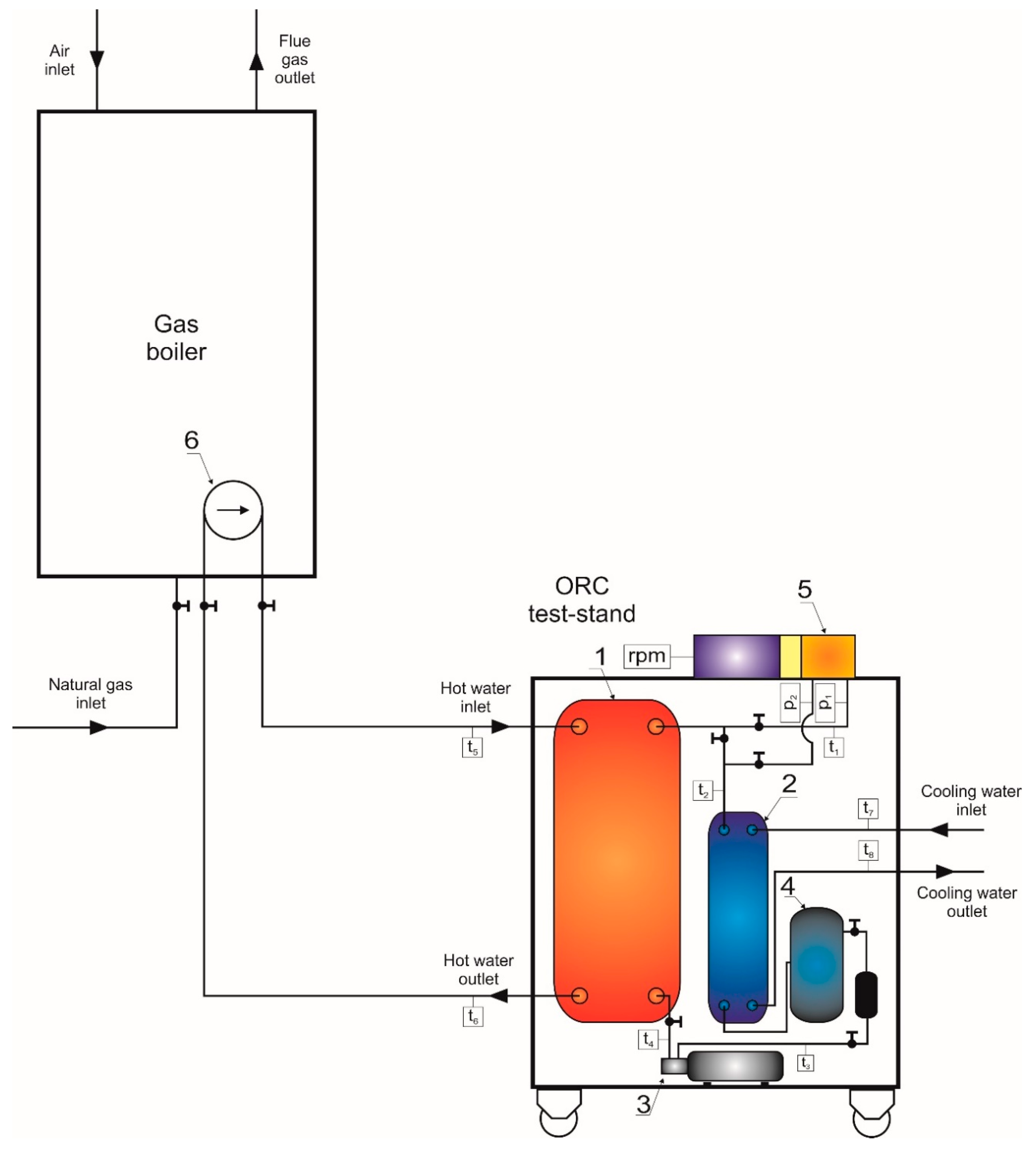
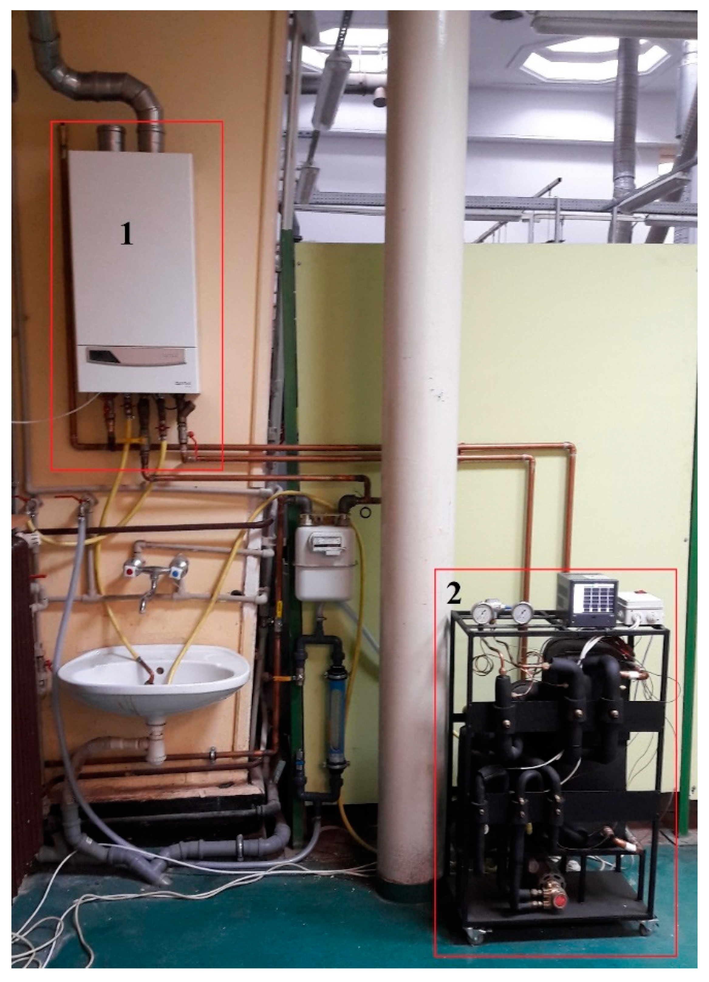
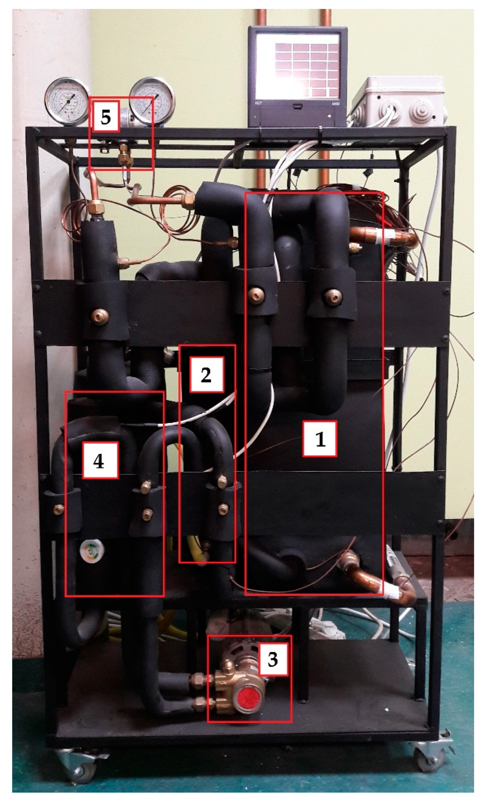
3.1. Description of the Test-Stand
3.2. The Experimental Description
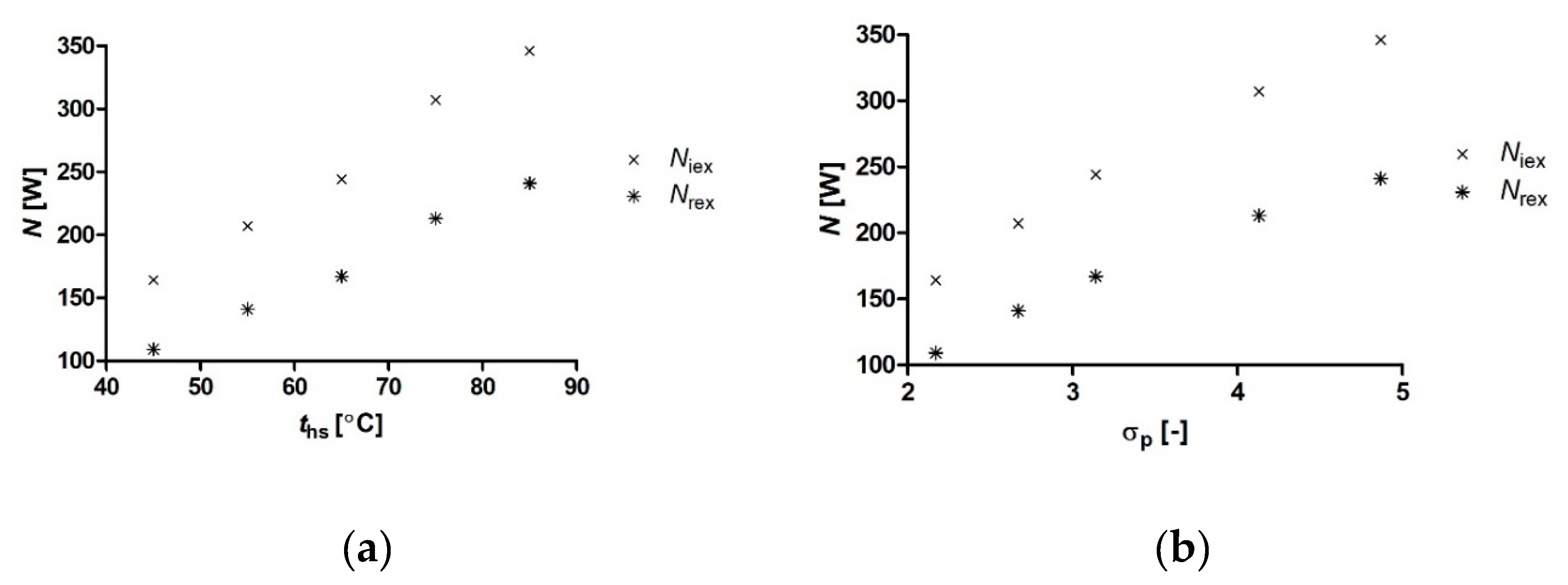
4. Experimental Results and Discussion
5. Summary and Conclusions
Funding
Acknowledgments
Conflicts of Interest
References
- Kumar, P.; Pirjola, L.; Ketzel, M.; Harrison, R.M. Nanoparticle emissions from 11 non-vehicle exhaust sources—A review. Atmos. Environ. 2013, 67, 252–277. [Google Scholar] [CrossRef]
- Commodo, M.; Sgro, L.A.; D’Anna, A.; Minutolo, P. Size Distribution of Nanoparticles Generated by a Heating Stove Burning Wood Pellets. Int. J. Environ. Qual. 2012, 8, 21–26. [Google Scholar]
- Saikia, B.K.; Saikia, J.; Rabha, S.; Silva, L.F.O.; Finkelman, R. Ambient nanoparticles/nanominerals and hazardous elements from coal combustion activity: Implications on energy challenges and health hazards. Geosci. Front. 2018, 9, 863–875. [Google Scholar] [CrossRef]
- Nussbaumer, T.; Doberer, A.; Klippel, N.; Bühler, R.; Vock, W. Influence of Ignition and Operation Type on Particle Emissions from Residential Wood Combustion. In Proceedings of the 16th European Biomass Conference and Exhibition, Valencia, Spain, 2–6 June 2008. [Google Scholar]
- Annesi-Maesano, I. The Air of Europe: Where are we going? Eur. Respir. Rev. 2017, 26, 170024. [Google Scholar] [CrossRef] [PubMed]
- Collective work. Air Quality in Europe—2019 Report; European Environment Agency: Copenhagen, Denmark, 2019. [Google Scholar]
- Hata, M.; Chomanee, J.; Thongyen, T.; Bao, L.; Tekasakul, S.; Tekasakul, P.; Otani, Y.; Furuuchi, M. Characteristics of nanoparticles emitted from burning of biomass fuels. J. Environ. Sci. 2014, 26, 1913–1920. [Google Scholar] [CrossRef] [PubMed]
- Johansson, L.S.; Tullin, C.; Leckner, B.; Sjövall, P. Particle emissions from biomass combustion in small combustors. Biomass Bioenergy 2003, 25, 435–446. [Google Scholar] [CrossRef]
- Burtscher, H. The origin and Production of Nanoparticles in Environment and Industry. In Nanoparticles in Medicine and Environment: Inhalation and Health Effects; Springer: Dordrecht, The Netherlands, 2009. [Google Scholar]
- Triantafyllou, A.G. Levels and trend of suspended particles around large lignite power stations. Environ. Monit. Assess. 2003, 89, 15–34. [Google Scholar] [CrossRef]
- Shanthakumar, S.; Singh, D.N.; Phadke, R.C. Flue gas conditioning for reducing suspended particulate matter from thermal power stations. Prog. Energy Combust. Sci. 2008, 34, 685–695. [Google Scholar] [CrossRef]
- Zhiqiang, Q.; Siegmann, K.; Keller, A.; Matter, U.; Scherrer, L.; Siegmann, H.C. Nanoparticle air pollution in major cities and its origin. Atmos. Environ. 2000, 34, 443–451. [Google Scholar] [CrossRef]
- World Health Organization. Air Pollution. Available online: www.who.int/news-room/fact-sheets/detail/ambient-(outdoor)-air-quality-and-health (accessed on 8 June 2020).
- European Environment Agency. Cutting air Pollution in Europe would Prevent Early Deaths, Improve Productivity and Curb Climate Change. Available online: https://www.eea.europa.eu/highlights/cutting-air-pollution-in-europe (accessed on 8 June 2020).
- Calderón-Garcidueñas, L.; González-Maciel, A.; Mukherjee, P.S.; Reynoso-Robles, R.; Pérez-Guillé, B.; Gayosso-Chávez, C.; Torres-Jardón, R.; Cross, J.V.; Ahmed, I.A.M.; Karloukovski, V.V.; et al. Combustion- and friction-derived magnetic air pollution nanoparticles in human hearts. Environ. Res. 2019, 176, 108567. [Google Scholar] [CrossRef]
- Calderón-Garcidueñas, L.; González-Maciel, A.; Kulesza, R.J.; González-González, L.O.; Reynoso-Robles, R.; Mukherjee, P.S.; Torres-Jardón, R. Air Pollution, Combustion and Friction Derived Nanoparticles, and Alzheimer’s Disease in Urban Children and Young Adults. J. Alzheimers Dis. 2019, 70, 343–360. [Google Scholar] [CrossRef] [PubMed]
- Jayaraj, R.L.; Rodriguez, E.A.; Wang, Y.; Block, M.L. Outdoor Ambient Air Pollution and Neurodegenerative Diseases: The Neuroinflammation Hypothesis. Curr. Environ. Health Rep. 2017, 4, 166–179. [Google Scholar] [CrossRef] [PubMed]
- Eurostat. Air Pollution Statistics—Emission Inventories. Available online: https://ec.europa.eu/eurostat/statistics-explained/index.php/Air_pollution_statistics_-_emission_inventories#Fine_particulate_matter (accessed on 8 June 2020).
- Collective work. Environment 2019; Główny Urząd Statystyczny: Warsaw, Poland, 2019.
- US Department of Energy. Furnaces and Boilers. Available online: https://www.energy.gov/energysaver/home-heating-systems/furnaces-and-boilers (accessed on 8 June 2020).
- Kruczek, S. Kotły; Wrocław University of Technology Publishing: Wrocław, Poland, 2001. [Google Scholar]
- Kowalski, C. Kotły Gazowe Centralnego Ogrzewania; WNT: Warszawa, Poland, 1994. [Google Scholar]
- Herrando, M.; Markides, C.N.; Hellgardt, K. A UK-based assessment of hybrid PV and solar-thermal systems for domestic heating and power: System performance. Appl. Energy 2014, 122, 288–309. [Google Scholar] [CrossRef]
- Chen, H.; Riffat, S.B.; Fu, Y. Experimental study on a hybrid photovoltaic/heat pump system. Appl. Therm. Eng. 2011, 31, 4132–4138. [Google Scholar] [CrossRef]
- Kolasiński, P. Application of the Multi-Vane Expanders in ORC Systems—A Review on the Experimental and Modeling Research Activities. Energies 2019, 12, 2975. [Google Scholar] [CrossRef]
- Bao, J.; Zhao, L. A review of working fluid and expander selections for organic Rankine cycle. Renew. Sustain. Energy Rev. 2013, 24, 325–342. [Google Scholar] [CrossRef]
- Elmer, T.; Worall, M.; Wu, S.; Riffat, S.B. Fuel cell technology for domestic built environment applications: State of-the-art review. Renew. Sustain. Energy Rev. 2015, 42, 913–931. [Google Scholar] [CrossRef]
- Staffell, I.; Ingram, A.; Kendall, K. Energy and carbon payback times for solid oxide fuel cell based domestic CHP. Int. J. Hydrog. Energy 2012, 37, 2509–2523. [Google Scholar] [CrossRef]
- Visser, W.P.J.; Shakariyants, S.A.; Oostveen, M. Development of a 3 kW microturbine for CHP applications. J. Eng. Gas Turbines Power 2011, 133, 042301. [Google Scholar] [CrossRef]
- Conroy, G.; Duffy, A.; Ayompe, L.M. Economic, energy and GHG emissions performance evaluation of a WhisperGen Mk IV Stirling engine μ-CHP unit in a domestic dwelling. Energy Convers. Manag. 2014, 81, 465–474. [Google Scholar] [CrossRef]
- Wajs, J.; Mikielewicz, D.; Bajor, M.; Kneba, Z. Experimental investigation of domestic micro-CHP based on the gas boiler fitted with ORC module. Arch. Thermodyn. 2016, 37, 79–93. [Google Scholar] [CrossRef]
- Liu, X.; O’Rear, E.G.; Tyner, W.E.; Pekny, J.F. Purchasing vs. leasing: A benefit-cost analysis of residential solar PV panel use in California. Renew. Energy 2014, 66, 770–774. [Google Scholar] [CrossRef]
- Staffell, I.; Green, R. The cost of domestic fuel cell micro-CHP systems. Int. J. Hydrog. Energy 2013, 38, 1088–1102. [Google Scholar] [CrossRef]
- Poppi, S.; Sommerfeldt, N.; Bales, C.; Madani, H.; Lundqvist, P. Techno-economic review of solar heat pump systems for residential heating applications. Renew. Sustain. Energy Rev. 2018, 81, 22–32. [Google Scholar] [CrossRef]
- Do Nascimento, M.; Rodrigues, L.; dos Santos, E.; Gomes, E.; Dias, F.; Velásques, E.; Carrillo, R. Micro Gas Turbine Engine: A Review. In Progress in Gas Turbine Performance; IntechOpen: London, UK, 2014. [Google Scholar]
- Proctor, C. Cool Energy Turns Waste Heat into Power with 200-Year-old Technology. Denver Business Journal, 3 July 2014. Available online: https://www.bizjournals.com/denver/blog/earth_to_power/2014/07/cool-energy-turns-waste-heat-into-power-with-200.html (accessed on 8 June 2020).
- Lai, N.A.; Wendland, M.; Fischer, J. Working fluid for high-temperature organic Rankine cycles. Energy 2011, 36, 199–211. [Google Scholar] [CrossRef]
- He, C.; Liu, C.; Gao, H.; Xie, H.; Li, Y.; Wu, S.; Xu, J. The Optimal Evaporation Temperature and Working Fluids for Subcritical Organic Rankine Cycle. Energy 2012, 38, 136–143. [Google Scholar] [CrossRef]
- Györke, G.; Deiters, U.K.; Groniewsky, A.; Lassu, I.; Imre, A.R. Novel classification of pure working fluids for Organic Rankine Cycle. Energy 2018, 145, 288–300. [Google Scholar] [CrossRef]
- Imre, A.R.; Kustán, R.; Groniewsky, A. Thermodynamic Selection of the Optimal Working Fluid for Organic Rankine Cycles. Energies 2019, 12, 2028. [Google Scholar] [CrossRef]
- Zhang, X.; Zhang, Y.; Cao, M.; Wang, J.; Wu, Y.; Ma, C. Working Fluid Selection for Organic Rankine Cycle Using Single-Screw Expander. Energies 2019, 12, 3197. [Google Scholar] [CrossRef]
- White, J.A.; Velasco, S. Approximating the Temperature–Entropy Saturation Curve of ORC Working Fluids From the Ideal Gas Isobaric Heat Capacity. Energies 2019, 12, 3266. [Google Scholar] [CrossRef]
- Invernizzi, C.M.; Ayub, A.; Di Marcoberardino, G.; Iora, P. Pure and Hydrocarbon Binary Mixtures as Possible Alternatives Working Fluids to the Usual Organic Rankine Cycles Biomass Conversion Systems. Energies 2019, 12, 4140. [Google Scholar] [CrossRef]
- Hung, T.C.; Wang, S.K.; Kuo, C.H.; Pei, B.S.; Tsai, K.F. A study of organic working fluids on system efficiency of an ORC using low-grade energy sources. Energy 2010, 35, 1403–1411. [Google Scholar] [CrossRef]
- Wang, E.H.; Zhang, H.G.; Fan, B.Y.; Ouyang, M.G.; Zhao, Y.; Mu, Q.H. Study of working fluid selection of organic Rankine cycle (ORC) for engine waste heat recovery. Energy 2011, 36, 3406–3418. [Google Scholar] [CrossRef]
- Setiawan, D.; Subrata, I.D.M.; Purwanto, Y.A.; Tambunan, A.H. Evaluation of Working Fluids for Organic Rankine Cycle Based on Exergy Analysis. IOP Conf. Ser. Earth Environ. Sci. 2018, 147, 12035. [Google Scholar] [CrossRef]
- Siddiqi, M.A.; Atakan, B. Investigation of the Criteria for Fluid Selection in Rankine Cycles for Waste Heat Recovery. Int. J. Thermodyn. 2011, 14, 117–123. [Google Scholar]
- Dai, X.; Shi, L.; Qian, W. Review of the Working Fluid Thermal Stability for Organic Rankine Cycles. J. Therm. Sci. 2019, 14, 597–607. [Google Scholar] [CrossRef]
- Kolasiński, P. The Method of the Working Fluid Selection for Organic Rankine Cycle (ORC) System with Volumetric Expander. In Proceedings of the 3rd International Seminar on ORC Power Systems, Brussels, Belgium, 12–14 October 2015. [Google Scholar]
- Kolasiński, P. The Method of the Working Fluid Selection for Organic Rankine Cycle (ORC) Systems Employing Volumetric Expanders. Energies 2020, 13, 573. [Google Scholar] [CrossRef]
- Harrison, J. Stirling Engine Systems for Small and Micro Combined Heat and Power (CHP) Applications. In Small and Micro Combined Heat and Power (CHP) Systems; Woodhead Publishing: Cambridge, UK, 2011. [Google Scholar]
- Alshammari, F.; Usman, M.; Pesyridis, A. Expanders for Organic Rankine Cycle Technology. In Organic Rankine Cycle Technology for Heat Recovery; IntechOpen: London, UK, 2018. [Google Scholar]
- Lemort, V.; Legros, A. Positive Displacement Expanders for Organic Rankine Cycle Systems. In Organic Rankine Cycle (ORC) Power Systems: Technologies and Applications; Woodhead Publishing: Cambridge, UK, 2017. [Google Scholar]
- Gnutek, Z.; Kolasiński, P. The application of rotary vane expanders in ORC systems—Thermodynamic description and experimental results. J. Eng. Gas Turbines Power 2013, 135, 61901. [Google Scholar] [CrossRef]
- Usman, M.; Pesyridis, A.; Cockerill, S.; Howard, T. Development and Testing of a Free Piston Linear Expander for Organic Rankine Cycle Based Waste Heat Recovery Application. In Proceedings of the 5th International Seminar on ORC Power Systems, Athens, Greece, 9–11 September 2019. [Google Scholar]
- Latz, G.; Erlandsson, O.; Skåre, T.; Contet, A.; Andersson, S.; Munch, K. Performance Analysis of a Reciprocating Piston Expander and a Plate Type Exhaust Gas Recirculation Boiler in a Water-Based Rankine Cycle for Heat Recovery from a Heavy Duty Diesel Engine. Energies 2016, 9, 495. [Google Scholar] [CrossRef]
- Bianchi, M.; Branchini, L.; Casari, N.; De Pascale, A.; Melino, F.; Ottaviano, S.; Pinelli, M.; Spina, P.R.; Suman, A. Experimental analysis of a micro-ORC driven by piston expander for low-grade heat recovery. Appl. Therm. Eng. 2019, 148, 1278–1291. [Google Scholar] [CrossRef]
- Wronski, J.; Imran, M.; Skovrup, M.J.; Haglind, F. Experimental and numerical analysis of a reciprocating piston expander with variable valve timing for small-scale organic Rankine cycle power systems. Appl. Energy 2019, 247, 403–416. [Google Scholar] [CrossRef]
- Oudkerk, J.F.; Dickes, R.; Dumont, O.; Lemort, V. Experimental performance of a piston expander in a small- scale organic Rankine cycle. IOP Conf. Ser. Mater. Sci. Eng. 2015, 90, 12066. [Google Scholar] [CrossRef]
- Glavatskaya, Y.; Podevin, P.; Lemort, V.; Shonda, O.; Descombes, G. Reciprocating Expander for an Exhaust Heat Recovery Rankine Cycle for a Passenger Car Application. Energies 2012, 5, 1751–1765. [Google Scholar] [CrossRef]
- Li, G.; Zhang, H.; Yang, F.; Song, S.; Chang, Y.; Yu, F.; Wang, J.; Yao, B. Preliminary Development of a Free Piston Expander–Linear Generator for Small-Scale Organic Rankine Cycle (ORC) Waste Heat Recovery System. Energies 2016, 9, 300. [Google Scholar] [CrossRef]
- Hsu, S.-W.; Chiang, H.-W.D.; Yen, C.-W. Experimental Investigation of the Performance of a Hermetic Screw-Expander Organic Rankine Cycle. Energies 2014, 7, 6172–6185. [Google Scholar] [CrossRef]
- Zhang, Y.-Q.; Wu, Y.-T.; Xia, G.-D.; Ma, C.-F.; Ji, W.-N.; Liu, S.-W.; Yang, K.; Yang, F.-B. Development and experimental study on organic Rankine cycle system with single-screw expander for waste heat recovery from exhaust of diesel engine. Energy 2014, 77, 499–508. [Google Scholar] [CrossRef]
- Tang, H.; Wu, H.; Wang, X.; Xing, Z. Performance study of a twin-screw expander used in a geothermal organic Rankine cycle power generator. Energy 2015, 90, 631–642. [Google Scholar] [CrossRef]
- Öhman, H.; Lundqvist, P. Screw Expanders in ORC Applications, Review and A New Perspective. In Proceedings of the 3rd International Seminar on ORC Power Systems, Brussels, Belgium, 12–14 October 2015. [Google Scholar]
- Kim, Y.M.; Shin, D.G.; Kim, C.G. Optimization of Design Pressure Ratio of Positive Displacement Expander for Vehicle Engine Waste Heat Recovery. Energies 2014, 7, 6105–6117. [Google Scholar] [CrossRef]
- Kaczmarczyk, T.; Ihnatowicz, E.; Żywica, G.; Kiciński, J. Experimental investigation of the ORC system in a cogenerative domestic power plant with a scroll expanders. Open Eng. 2015, 5, 411–420. [Google Scholar] [CrossRef]
- Gao, P.; Jiang, L.; Wang, L.W.; Wang, R.Z.; Song, F.P. Simulation and experiments on an ORC system with different scroll expanders based on energy and exergy analysis. Appl. Therm. Eng. 2015, 75, 880–888. [Google Scholar] [CrossRef]
- Jradi, M.; Li, J.; Liu, H.; Riffat, S. Micro-scale ORC-based combined heat and power system using a novel scroll expander. Int. J. Low Carbon Technol. 2014, 9, 91–99. [Google Scholar] [CrossRef][Green Version]
- Dumont, O.; Parthoens, A.; Dickes, R.; Lemort, V. Experimental investigation and optimal performance assessment of four volumetric expanders (scroll, screw, piston and roots) tested in a small-scale organic Rankine cycle system. Energy 2018, 165, 1119–1127. [Google Scholar] [CrossRef]
- Song, P.; Wei, M.; Liu, Z.; Zhao, B. Effects of suction port arrangements on a scroll expander for a small scale ORC system based on CFD approach. Appl. Energy 2015, 150, 274–285. [Google Scholar] [CrossRef]
- Emhardt, S.; Tian, G.; Chew, J. A review of scroll expander geometries and their performance. Appl. Therm. Eng. 2018, 141, 1020–1034. [Google Scholar] [CrossRef]
- Kim, D.; Chung, H.J.; Jeon, Y.; Jang, D.S.; Kim, Y. Optimization of the injection-port geometries of a vapor injection scroll compressor based on SCOP under various climatic conditions. Energy 2017, 135, 442–454. [Google Scholar] [CrossRef]
- Kurkus-Gruszecka, M.; Krawczyk, P. Comparison of Two Single Stage Low-Pressure Rotary Lobe Expander Geometries in Terms of Operation. Energies 2019, 12, 4512. [Google Scholar] [CrossRef]
- Kurkus-Gruszecka, M.; Krawczyk, P.; Badyda, K. CFD modelling of a fluid flow in a rotary lobe expander. In Proceedings of the International Conference of Numerical Analysis and Applied Mathematics (ICNAAM 2018), Athens, Greece, 13–18 September 2018. [Google Scholar]
- Bianchi, G.; Fatigati, F.; Murgia, S.; Cipollone, R. Design and analysis of a sliding vane pump for waste heat to power conversion systems using organic fluids. Appl. Therm. Eng. 2017, 124, 1038–1048. [Google Scholar] [CrossRef]
- Kolasiński, P. The Influence of the Heat Source Temperature on the Multivane Expander Output Power in an Organic Rankine Cycle (ORC) System. Energies 2015, 8, 3351–3369. [Google Scholar] [CrossRef]
- Kolasiński, P.; Błasiak, P.; Rak, J. Experimental and Numerical Analyses on the Rotary Vane Expander Operating Conditions in a Micro Organic Rankine Cycle System. Energies 2016, 9, 606. [Google Scholar] [CrossRef]
- Rak, J.; Błasiak, P.; Kolasiński, P. Influence of the Applied Working Fluid and the Arrangement of the Steering Edges on Multi-Vane Expander Performance in Micro ORC System. Energies 2018, 11, 892. [Google Scholar]
- Bell, I.H.; Wronski, J.; Quoilin, S.; Lemort, V. Pure and Pseudo-pure Fluid Thermophysical Property Evaluation and the Open-Source Thermophysical Property Library CoolProp. Ind. Eng. Chem. Res. 2014, 53, 2498–2508. [Google Scholar] [CrossRef] [PubMed]
- Zangheri, P.; Armani, R.; Pietrobon, M.; Pagliano, L.; Boneta, M.; Müller, A. Heating and Cooling Energy Demand and Loads for Building Types in Different Countries of the EU; Politecnico di Milano: Milano, Italy, 2014. [Google Scholar]
- Quintero, R.; Genty, A.; Vieitez, E.; Wolf, O. Development of Green Public Procurement Criteria for Water-Based Heaters; Publications Office of the European Union: Luxembourg, 2014. [Google Scholar]
- Baborska-Narożny, M.; Szulgowska-Zgrzywa, M.; Mokrzecka, M.; Chmielewska, A.; Fidorow-Kaprawy, N.; Stefanowicz, E.; Piechurski, K.; Laska, M. Climate justice: Air quality and transitions from solid fuel heating. Build. Cities 2020, 1, 120–140. [Google Scholar] [CrossRef]
- Collective Work. Housing Conditions in Poland in 2017; Główny Urząd Statystyczny: Warsaw, Poland, 2018.


| Source of Dust Emission | Emission Tonnes |
|---|---|
| Energy production and distribution | 49,716 |
| Energy use in industry | 108,887 |
| Road transport | 142,621 |
| Non-road transport | 32,085 |
| Commercial, institutional and households | 732,863 |
| Industrial processes and product use | 142,801 |
| Agriculture | 44,137 |
| Waste | 50,773 |
| Other | 485 |
| Total sectors of emissions for the national territory | 1,304,368 |
| Source of Dust Emission | Emission Tonnes |
|---|---|
| Power generating plants | 10,400 |
| Industrial power plants | 35,500 |
| Industrial technologies | 34,700 |
| Households | 122,000 |
| Other stationary sources (local boiler plants, trade, workshops, agriculture and others) | 102,600 |
| Mobile sources | 35,500 |
| Total | 340,700 |
| Fuel Type | Vdaf % | Qwr MJ/kg |
|---|---|---|
| Flame coal | 30 | 25.0 |
| Wheat | 63–78 | 14.3–15.2 |
| Waste wood | 55–81 | 13.0 |
| Natural gas | 100 | 43.0 |
| Heating oil | 0 | 39.7–42.7 |
| Technology Type | Investment Costs EUR/kW | Overall Efficiency % | Electrical Efficiency % | Electricity/Heat Supply Ratio kWe/kWt | Part-Load Flexibility | Ref. |
|---|---|---|---|---|---|---|
| PV cell | 1700 | - | 14–16 | 5/- | Yes | [32] |
| Fuel cell | 890 | 70–92 | 37–55 | 0.75/0.9–30.8 | No | [33] |
| Heat pump | 350 | 4–5 | - | -/30 | Yes | [34] |
| ORC system | 1000 | 90 | 10 | 2.5–10/11–44 | Yes | [25] |
| Micro CHP gas turbine | 360 | 90 | 26 | 30/30 | No | [35] |
| Stirling engine | 2200 | 90 | 15 | 2–10/4–35 | Yes | [36] |
| No. | Working Fluid | Triple Point Temperature | Normal Boiling Point Temperature | Critical Point Parameters | ODP | GWP | Working Fluid Class [39] | ||
|---|---|---|---|---|---|---|---|---|---|
| ttrp °C | tnbp °C | tcr °C | pcr MPa | ρcr kg/m3 | |||||
| 1 | R113 | −36.22 | 47.59 | 214.06 | 3.39 | 560.00 | 0.8 | 4800 | ANZCM |
| 2 | R114 | −92.52 | 3.59 | 145.68 | 3.25 | 579.97 | 1.0 | 3.9 | AZCM |
| 3 | R123 | −107.15 | 27.82 | 183.68 | 3.66 | 550.00 | 0.02 | 77 | ACNMZ |
| 4 | R124 | −199.15 | −11.96 | 122.28 | 3.62 | 560.00 | 0.02 | 620 | ACNZM |
| 5 | R1234ze | −104.53 | −18.95 | 109.37 | 3.63 | 489.24 | 0 | 6 | ACNZM |
| 6 | R134a | −103.30 | −26.07 | 101.06 | 4.06 | 512.00 | 0 | 1300 | ACZ |
| 7 | R152a | −118.59 | −24.02 | 113.26 | 4.51 | 368.00 | 0 | 120 | ACZ |
| 8 | R227ea | −128.60 | −16.34 | 101.75 | 2.93 | 594.25 | 0 | 3220 | ANCMZ |
| 9 | R236fa | −93.63 | −1.44 | 124.92 | 3.20 | 551.30 | 0 | 9810 | ACNMZ |
| 10 | R365mfc | −34.15 | 40.15 | 186.85 | 3.22 | 473.84 | 0 | 825 | ANZCM |
| 11 | R245ca | −81.65 | 25.13 | 174.42 | 3.39 | 523.59 | 0.12 | N/A | ANCMZ |
| 12 | R245fa | −102.10 | 15.14 | 154.01 | 3.65 | 516.08 | 0 | 1030 | ACNMZ |
| 13 | R601a | −160.50 | 27.83 | 187.2 | 3.38 | 236.00 | 0 | 20 | ANCMZ |
| 14 | R141b | −103.47 | 32.05 | 204.35 | 4.21 | 458.56 | 0.12 | 725 | ACNMZ |
| 15 | R142b | −130.43 | −9.12 | 137.11 | 4.05 | 446.00 | 0.07 | 2310 | ACNMZ |
| 16 | R236ea | −103.15 | 6.19 | 139.29 | 3.5 | 563.00 | 0 | 1330 | ANZCM |
| 17 | R600a | −159.42 | −11.75 | 134.66 | 3.63 | 225.5 | 0 | 3 | ACNMZ |
| 18 | RC318 | −39.80 | −5.97 | 115.23 | 2.78 | 620.00 | 0 | 10,300 | AZCM |
| 19 | R1234yf | −53.15 | −29.45 | 94.7 | 3.38 | 475.55 | 0 | 4 | ACNZM |
| 20 | R290 | −187.63 | −42.11 | 96.7 | 4.25 | 220.48 | 0 | 20 | ACZ |
| No. | ths (°C) | p1 (bara) | t1 (°C) | p2 (bara) | t2 (°C) | t3 (°C) | t4 (°C) | t5 (°C) | t6 (°C) | t7 (°C) | t8 (°C) | nex (rev/min) |
|---|---|---|---|---|---|---|---|---|---|---|---|---|
| 1 | 45 | 1.5 | 38.9 | 1.6 | 24.1 | 17.4 | 17.9 | 39.5 | 38.4 | 14.7 | 15.6 | 700 |
| 2 | 55 | 1.85 | 45.2 | 1.6 | 26.0 | 17.6 | 18.0 | 46.9 | 46.4 | 14.8 | 16.9 | 3280 |
| 3 | 65 | 2.2 | 50.9 | 1.6 | 28.1 | 17.9 | 18.3 | 52.7 | 51.6 | 15.0 | 19.1 | 3300 |
| 4 | 75 | 2.9 | 60.7 | 1.7 | 31.4 | 18.1 | 18.4 | 60.9 | 59.8 | 15.1 | 17.5 | 2900 |
| 5 | 85 | 3.4 | 66.7 | 1.7 | 33.4 | 18.0 | 18.6 | 71.5 | 65.9 | 15.1 | 18.3 | 2950 |
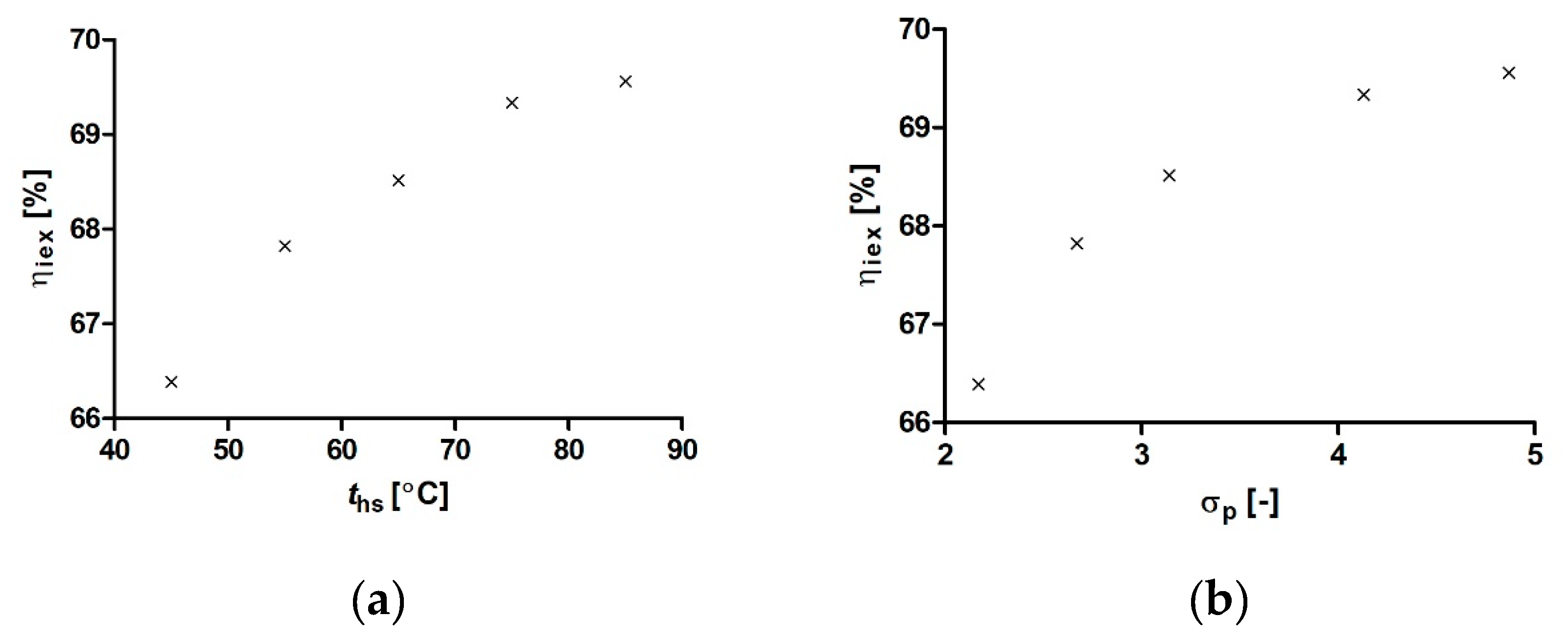
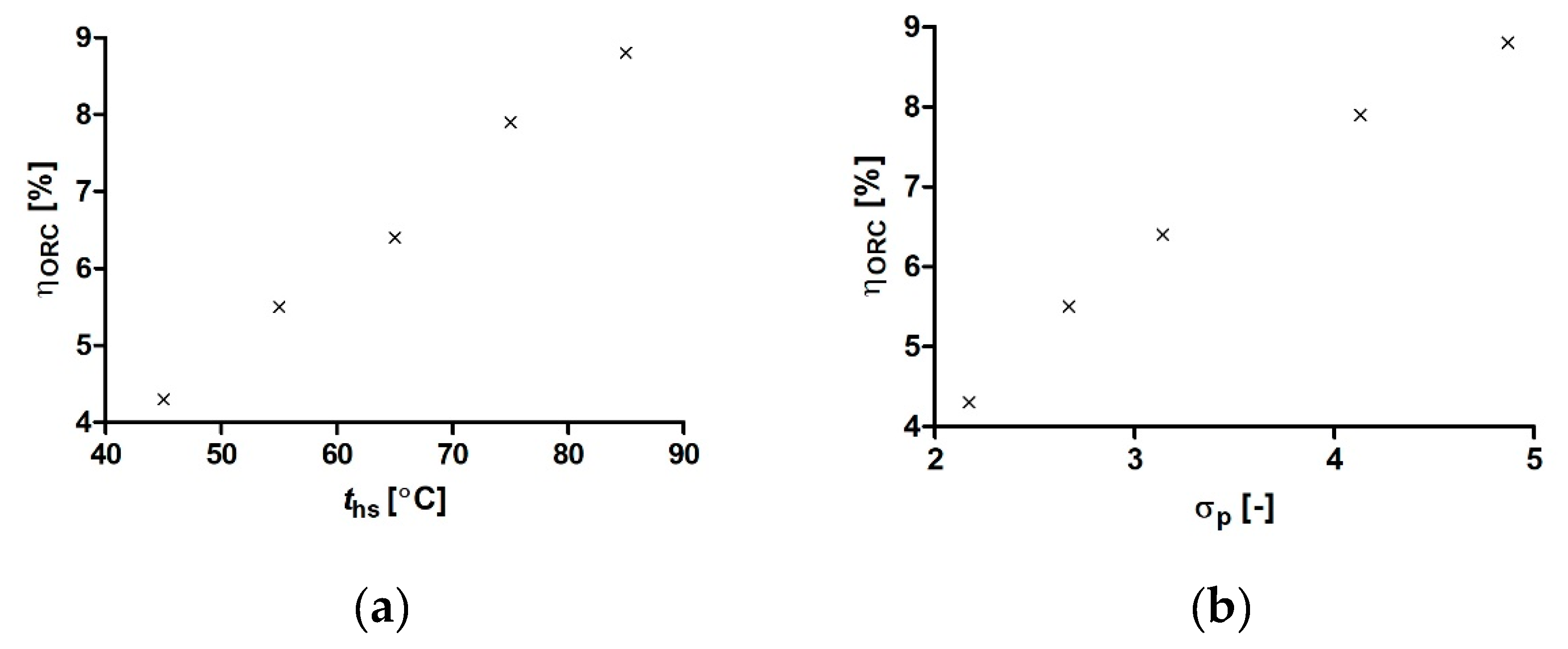
| No. | σp (-) | Niex (W) | Nrex (W) | ηiex (%) | QEV (W) | QCN (W) | ηORC (%) |
|---|---|---|---|---|---|---|---|
| 1 | 2.17 | 164 | 109 | 66.4 | 2525 | 2417 | 4.3 |
| 2 | 2.67 | 207 | 141 | 67.8 | 2572 | 2433 | 5.5 |
| 3 | 3.14 | 244 | 167 | 68.5 | 2613 | 2447 | 6.4 |
| 4 | 4.13 | 307 | 213 | 69.3 | 2687 | 2476 | 7.9 |
| 5 | 4.87 | 346 | 241 | 69.6 | 2735 | 2496 | 8.8 |
| Bolier Type | E mg/kWht | Es mg/m2⋅a | Eo mg/m2⋅a |
|---|---|---|---|
| Oil-fired bolier | 40 | 2800–4000 | 4800 |
| Gas-fired bolier | 5 | 350–500 | 600 |
| Coal-fired bolier | 280 | 19,600–28,000 | 33,600 |
| Wood-fired boiler (manually operated) | 140 | 9800–14000 | 16,800 |
| Wood-fired boiler (automatically controlled) | 65 | 4550–6500 | 7800 |
| Pellet-fired bolier | 40 | 2800–4000 | 4800 |
| Wood chips-fired boiler | 52 | 3640–5200 | 6240 |
| CHP unit | 0 | 0 | 0 |
© 2020 by the author. Licensee MDPI, Basel, Switzerland. This article is an open access article distributed under the terms and conditions of the Creative Commons Attribution (CC BY) license (http://creativecommons.org/licenses/by/4.0/).
Share and Cite
Kolasiński, P. Domestic Organic Rankine Cycle-Based Cogeneration Systems as a Way to Reduce Dust Emissions in Municipal Heating. Energies 2020, 13, 3983. https://doi.org/10.3390/en13153983
Kolasiński P. Domestic Organic Rankine Cycle-Based Cogeneration Systems as a Way to Reduce Dust Emissions in Municipal Heating. Energies. 2020; 13(15):3983. https://doi.org/10.3390/en13153983
Chicago/Turabian StyleKolasiński, Piotr. 2020. "Domestic Organic Rankine Cycle-Based Cogeneration Systems as a Way to Reduce Dust Emissions in Municipal Heating" Energies 13, no. 15: 3983. https://doi.org/10.3390/en13153983
APA StyleKolasiński, P. (2020). Domestic Organic Rankine Cycle-Based Cogeneration Systems as a Way to Reduce Dust Emissions in Municipal Heating. Energies, 13(15), 3983. https://doi.org/10.3390/en13153983