1. Introduction
In recent years, due to the exponential growth of electronic devices such as smartphones, tablets, portable computers and electric vehicles, it has become more important to appease the energy needs of such devices, to extend their use time without need of charging from stationary sources [
1,
2]. One of the crucial factors is the good compatibility and integration of the photovoltaic system, together with the battery integrated module [
3]. Vega-Garita et al. [
3] selected a suitable battery technology for the photovoltaic battery integrated module. Two Li-ion pouch cells were tested at two various temperatures while applying various charging/discharging cycles, concluding that the LiFePO
4 cells showed better performance than LiCoO
2 batteries, and were selected as a suitable option to be part of the photovoltaic (PV)-battery integrated module [
3].
In the literature are known control systems managing the efficient current transfer from photovoltaic module to the storage system [
1]. The voltage converter allows to supply electric devices whose current-voltage parameters do not allow direct connection. Its task is to change the value of current and voltage in a way that meets the requirements of the powered receiver, with the lowest possible power loss. Low power losses are synonymous with high processing efficiency. Depending on the converter type, the input voltage can be:
Tseng and Wang [
4] investigated a photovoltaic power system using a high step-up converter composed of two interleaved active clamp boost converters with a coupled inductor in a PV power system for DC load applications. An experimental prototype for DC load applications (P
PV(max) = 1.2 kW, P
VB(max) = 1.2 kW) was created and exhibited the efficiency of 91% under full load conditions [
4]. On the other hand, Irwanto et al. [
5] investigated in details photovoltaic powered DC-DC boost converter based on PID controller for a battery charging system.
In investigated systems second important element is solar (photovoltaic, PV) cell. The most popular PV modules, currently produced in the world, are those based on silicon solar cells [
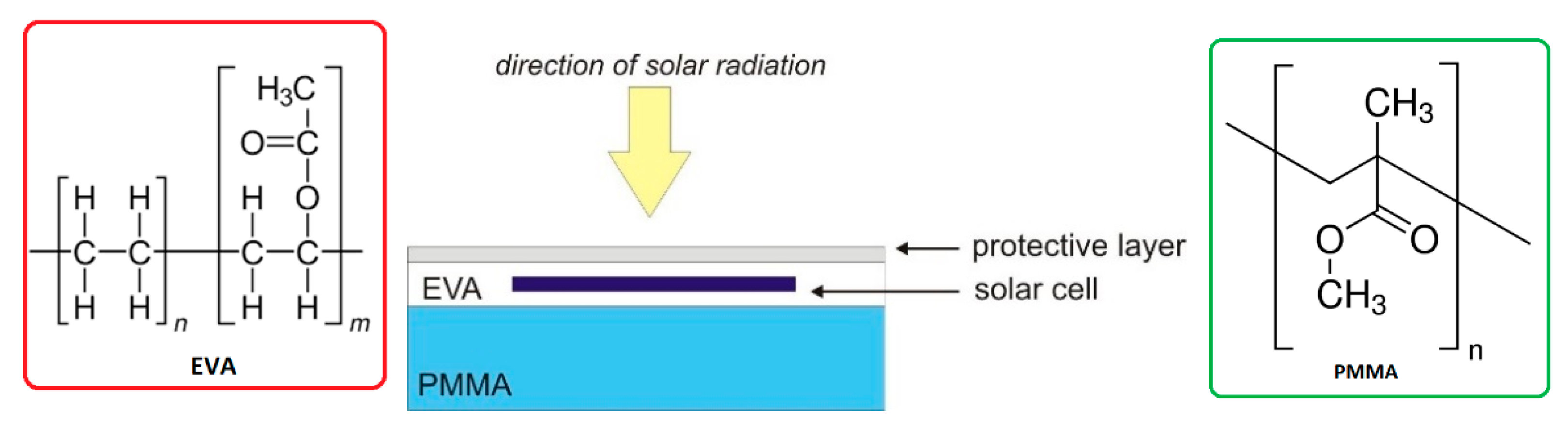
7]. A typical size of a solar panel is about 1.6 × 1 m, and the typical construction is based on a tempered glass carrier. Tempered glass has many advantages, such as high mechanical strength and resistance to weather conditions. It also has a major disadvantage: high weight per area of the whole module. One way to reduce the weight of a solar module is to replace glass with another, lighter material. In the proposed solution, the glass has been replaced with a sheet of poly(methyl methacrylate) (PMMA) [
8]. Thanks to this solution, the mass of the module decreased almost twice.
Moreover, it should be stressed that, recently, the attention was also drawn to the so-called coupled systems, i.e., photo-charging, in which the lithium-ion battery is connected to the photovoltaic cell [
9,
10]. Such a concept is intended not only to ensure the storage of energy obtained from solar cells, but also to give a possibility to have a support charging system using solar energy. This last idea seems to be very interesting due to its potential use in electrical vehicles. Such a solution would provide additional access to electricity, increasing the range of vehicles without the need to recharge the battery from an external source. For such solutions, an attempt was made for a lithium-ion battery combined with an inorganic solar cell (silicon) [
11], dye-sensitized solar cell (DSSC) [
12], polymer bulk heterojunction solar cell (BHJ) [
13,
14,
15] and perovskite solar cell [
15], giving efficiency η
conversion = 15%, η
storage = 97% and PCE = 14.5% for silicon solar cell, η
storage = 41% and PCE = 0.82% for DSSC, and η
conversion = 1.85% for BHJ cell connected with Li-polymer battery and η
conversion = 5.49% for BHJ connected to Li-ion battery, in turn for perovskite cell with Li-ion battery η
conversion = 7.8%.
It should be stressed that, last time, due to the great importance of electrochemical energy storage, many new materials and electrode architectures for batteries were presented in the recently published literature taking into consideration both materials and experiment aspects together with a stability and economics point of view [
16,
17,
18]. It is not easy to completely cover the current state of the field so widely investigated at the present time. Among the interesting aspects in energy storage system is the matter of flexibility of the constructed devices, where the key drawbacks include the degradation of energy output under external mechanical stresses, difficulties in delivering high energy output at small and versatile forms, safety, flexibility, and stability [
19,
20]. For example, Zhang et al. [
20] reviewed various electrically conductive hydrogels for flexible energy storage systems and concluding that “with the intense research from both academia and industry, we envision that the breakthrough of flexible energy storage technology will take place soon.” Other interesting aspects in storage energy system is ecology, especially the greenhouse effect debated at the present time. Dehghani-Sanij et al. [
21] make huge analyses of energy storage systems and environmental challenges of batteries. It is practical to assume that huge battery use will increase rapidly in the next generation. For this reason, a combination of different types of energy storage systems appears as the focal point, especially in terms of the effectiveness and efficiency of the system along with decreasing energy losses, costs, environmental impacts and health concerns [
21].
On the other hand, multi-objective home energy management with battery energy storage systems were widely investigated by Lokeshgupta et al. as one of the crucial requirements for a future smart grid environment [
22]. While, Terlouw et al. [
23] proposed multi-objective optimization of energy arbitrage in community energy storage systems using different battery technologies. In this work, the main objective was to minimize annual operation costs from grid electricity absorption and grid CO
2-emissions.
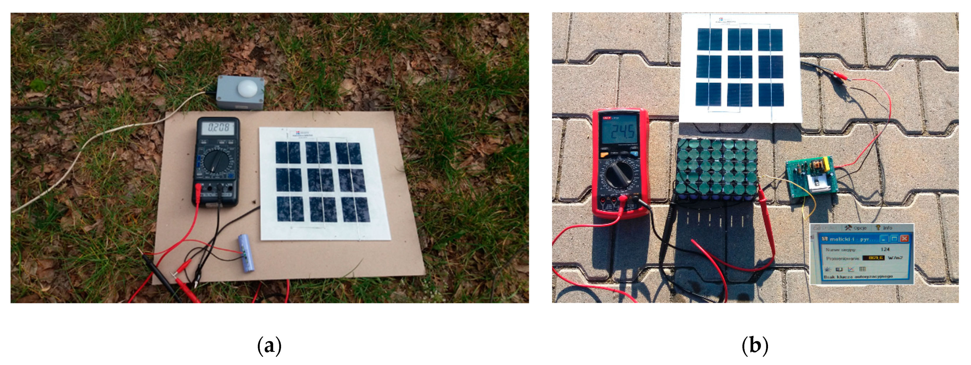
Based on the above described findings, the aim of our study was to design a simplistic and cheap electronic design of photovoltaic storage system that showed a good conversion efficiency. Images of an integrated system composed of one or 42 lithium-ion batteries and a new PV module is shown in
Figure 1.
The main goals of our work were:
- -
Reduction of weight of new PV module to about 7.5 kg by used poly(methyl methacrylate) (PMMA) as back sheet and ethylene-vinyl acetate (EVA) polymer with reduced crosslinking temperature as encapsulation materials.
- -
Investigation of energy storage systems based on new type of silicon photovoltaic module and one or 42 lithium ion batteries.
- -
Use of step-up voltage converters and battery management system (BMS) between the solar cell and lithium-ion battery to permit direct connection between the electricity storage and power supply, whose current-voltage parameters do not match.
- -
The step-up voltage converter will increase the end potential produced from photovoltaic module from 5 V up to 30 V.
- -
Investigation of photovoltaic parameters of the energy storage systems in laboratory and real conditions.
- -
Obtaining, in real conditions, the processing efficiency η = 0.75 for the energy storage systems with step-up voltage converters.
The article mainly concerns the concept of energy storage systems, especially the use of a non-standard photovoltaic module. A typical solar module is built of two tempered glass panes. This type of glass has many advantages, and one major disadvantage—high weight. It seems that it is easy to lower its weight by using plastic material instead of glass. Unfortunately, the protective polymers used (mainly EVA) do not have adequate adhesion to plastics. In the presented solution, the modification of the parameters of the lamination process allowed one to obtain EVA adhesion to PMMA at a satisfactory level.
2. Experimental
2.1. Materials
In our work, we used a commercially available cylindrical lithium-ion battery with dimensions 18.0 × 65.0 mm and a weight of 44 g (lithium-ion battery INR 18650-29E type) from Samsung. The standard parameters of the smallest: standard battery-charge rate 1.375 A; maximal battery-charge rate 2.75 A; maximal constant-discharge charge 2.75 A; maximal pulse-discharge charge 8.25 A.
Battery management system (BMS) is an electronic system that plays a protecting role against too low discharge and overcharge. It enables the construction of different stack configuration. For testing a single cylindrical battery, BMS-1S was used.
Potential conversion enables a connection between the energy source and receiving device for which the current-voltage parameters does not match. We propose the use of step-up converter allowing to increase from 5 V up to 30 V the end potential produced from photovoltaic module as an all-in-one solution. The converter was made of a transistor (BD 136), transformer (TR1) with two windings (Z1 = 21 windings, enameled winding wire 0.35 mm; Z2 = 120 windings, enameled winding wire 0.19 mm; ferromagnetic core type double E, 20 mm × 20 mm × 5 mm), three capacitors (electrolyte, C1: 1000 μF/16 V; polypropylene C2: 0,22 μF/250 V; electrolyte C3: 47 μF/50 V), two Schottky diodes (1A, 50 V) and a resistor (R1; 6.8 kΩ/1 W). All electronic components were supplied by ABC-RC shop (Tomice, Poland).
Monocrystalline silicon solar cells were received from BIG SUN Energy Technology Inc. Hukou Township, Taiwan. Poly(methyl methacrylate) (PMMA) is typical commercially available. Ethylene-vinyl acetate (EVA) was received from 3M (St. Paul, MN, USA).
2.2. Photovoltaic Module Construction
The described solution uses a mini photovoltaic module built of six monocrystalline silicon solar cells of size 5 × 5 cm. The PMMA sheet was used as the supporting layer in the module. As a protective layer for the solar cells, a thin film (with high transparency for solar radiation) was used. A copolymer ethylene-vinyl acetate (EVA) was used as the direct protective layer of the solar cells. The solar cells were connected in series by soldering with the plus and minus pins outside. A schematic cross-section of the mini module is shown in
Figure 2.
Our photovoltaic storage system was set to approx. 5 V for energy storage system requiring potential, which determine the number of photovoltaic cells, and the type of their connection is presented in
Figure 1. In this work we build photovoltaic module composed of nine photovoltaic cells, with declared maximum power of approx. 4.6 W, for standard laboratory irradiation 1000 W/m
2.
2.3. Energy Storage Systems Constructions
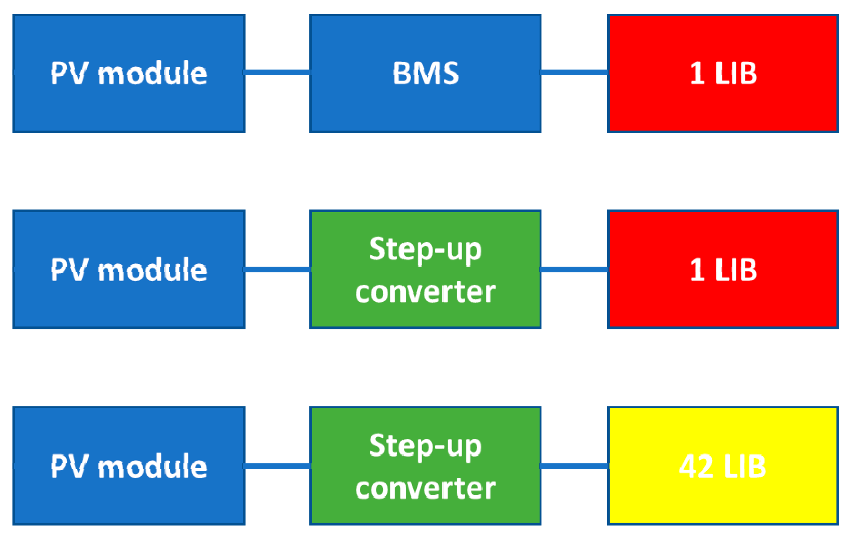
The main idea of this work was to test three types of energy storage systems based on PV module and one or a pack of 42 lithium-ion batteries (LIB) and BMS or step-up converter, as schematically presented in
Figure 3.
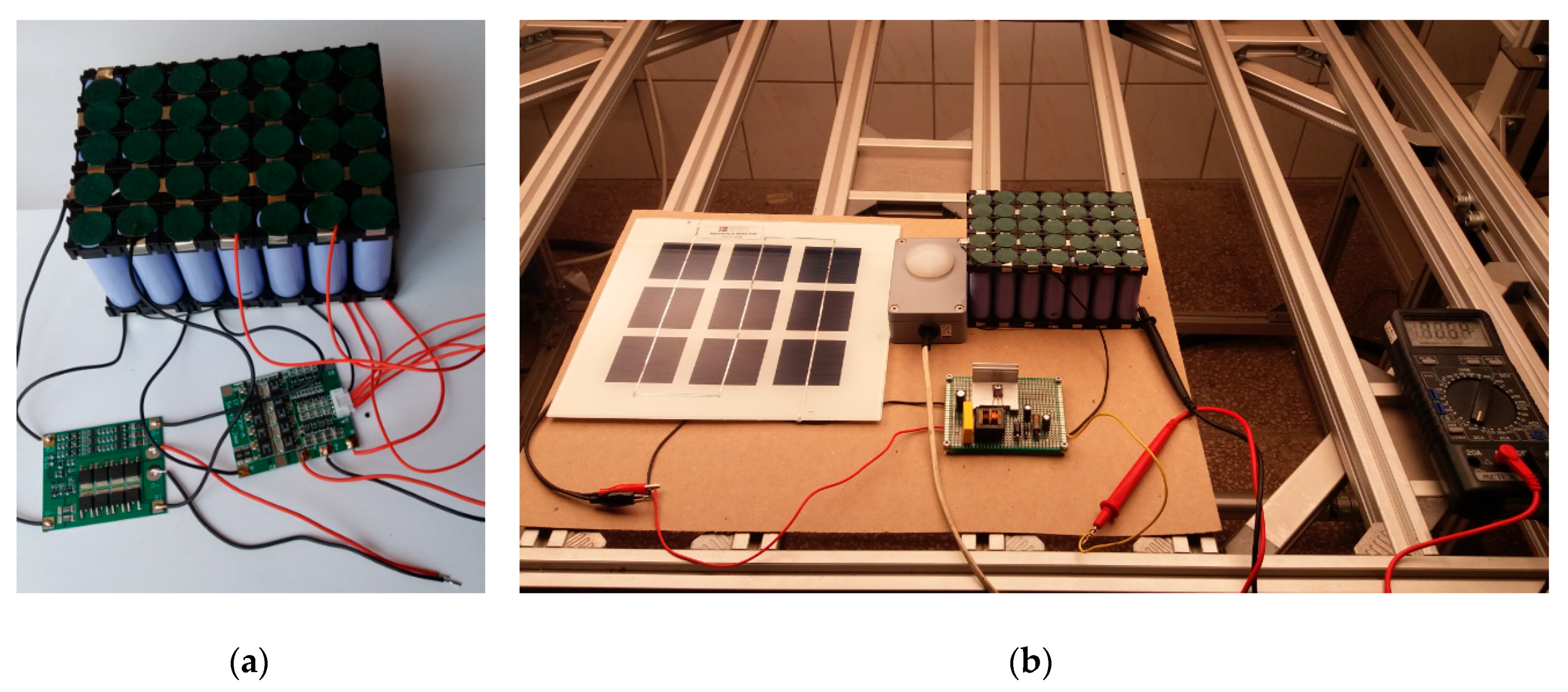
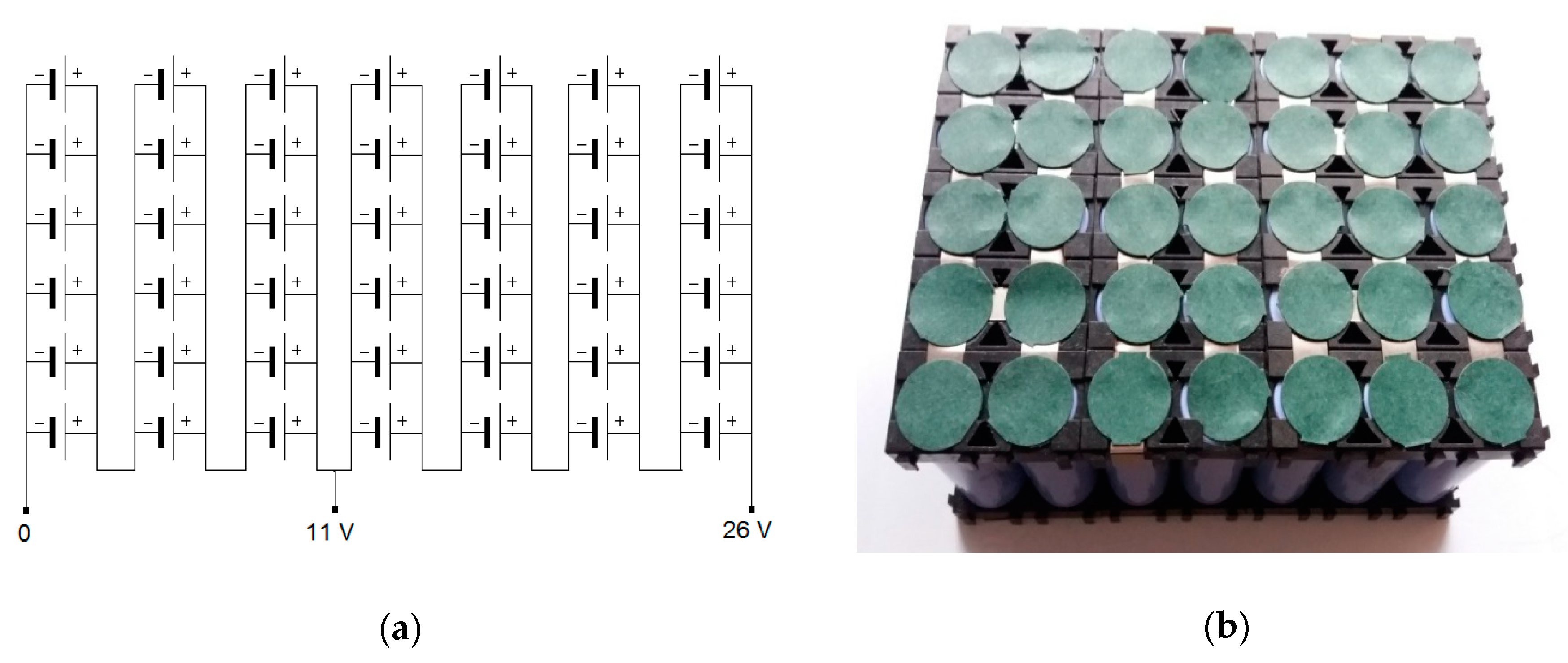
The energy storage unit was built of a single cylindrical lithium-ion battery (18,650 type), described above, aiming for 3.6 V or 3.7 V with total storage capacity equal 2900 mAh. Overall, 42 cylindrical batteries were connected by soldering technique with metallic tape and protected by insulating covers according to
Figure 4.
As can be seen in the scheme (
Figure 4), the energy storage unit shows mixed in line and in series connections: seven in series connections of six-inline batteries giving total of 26 V system. Additionally, it is possible to separate a 11 V module.
Moreover, the system was equipped with two commercial protection modules, BMS-3S and BMS-4S, allowing a connection of all seven packs of six batteries connected in lines (see
Figure 5a). Furthermore, the system was connected with a step-up converter, as shown in
Figure 5b.
2.4. Characterisation Methods
The measurements of photovoltaic parameters for solar module were performed. The scope of this study was to confirm the photovoltaic performance of silicon cells set in a module. The measurements were registered by current-voltage tracer model SC I-V CT-02 equipped with solar irradiation simulator model ST150AAA (PV Test Solutions, Wrocław, Poland). The tested system had 225 cm2 of active area.
3. Results and Discussions
3.1. Fabrication and Performance of Photovoltaic Module
The mini photovoltaic module used in the described system was made in the process of high temperature encapsulation. The lamination process of foil-EVA-PMMA systems was performed in a flat-bed laminator L200A (P-Energy, Fontaniva, Italy). Due to the fact that instead of a carrier layer made of tempered glass, a PMMA layer was used, the lamination process required major changes. Mainly, during the lamination process, the peak temperature at which EVA crosslinking occurs was reduced from 155 °C to 125 °C. To determine the cross-linking of polyethylene, the gel content test was used [
24,
25,
26]. To obtain the right level of gel content after the lamination process at such a low temperature, modified EVA was used. The modification was carried out by the EVA film producer. Examination of the gel content after the lamination process at 125 °C showed its proper level of 75% [
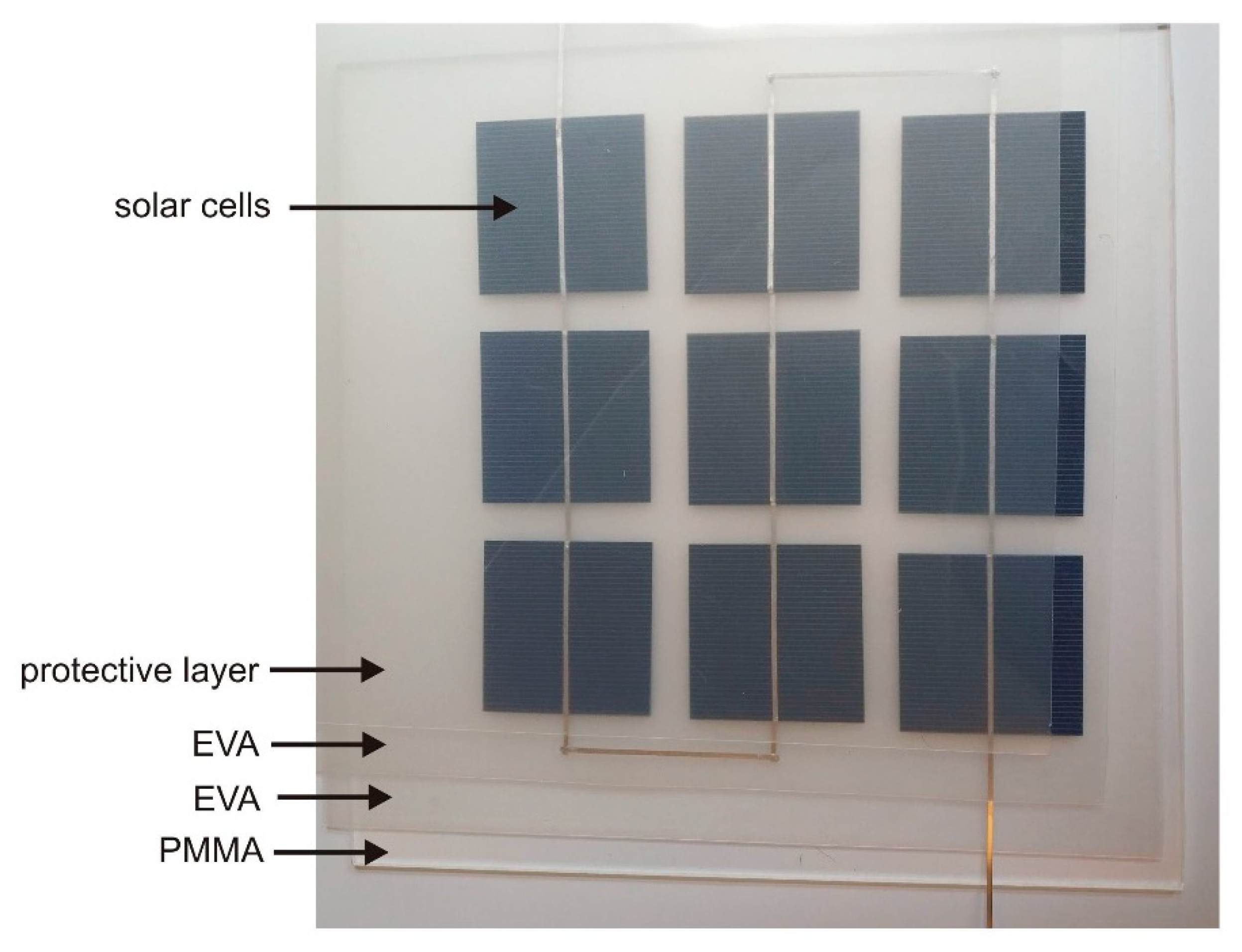
27]. However, the layering and lamination process stages were the same as for PV modules with tempered glass. Layout of material layers (and photovoltaic cells) in the mini module before the lamination process is shown in
Figure 6.
The used 5 cm × 5 cm cells were cut from 15.6 cm × 15.6 cm cells, using a 10 W and 532 nm wavelength laser. The cutting process was carried out from the rear contact side, so that the electrical parameters of the cell did not degrade. Cell conversion efficiency before and after the cutting process was the same and was about 18%. The weight of the completed module was 274 g. A module with identical dimensions and layering, but with tempered glass, had a weight of 492 g.
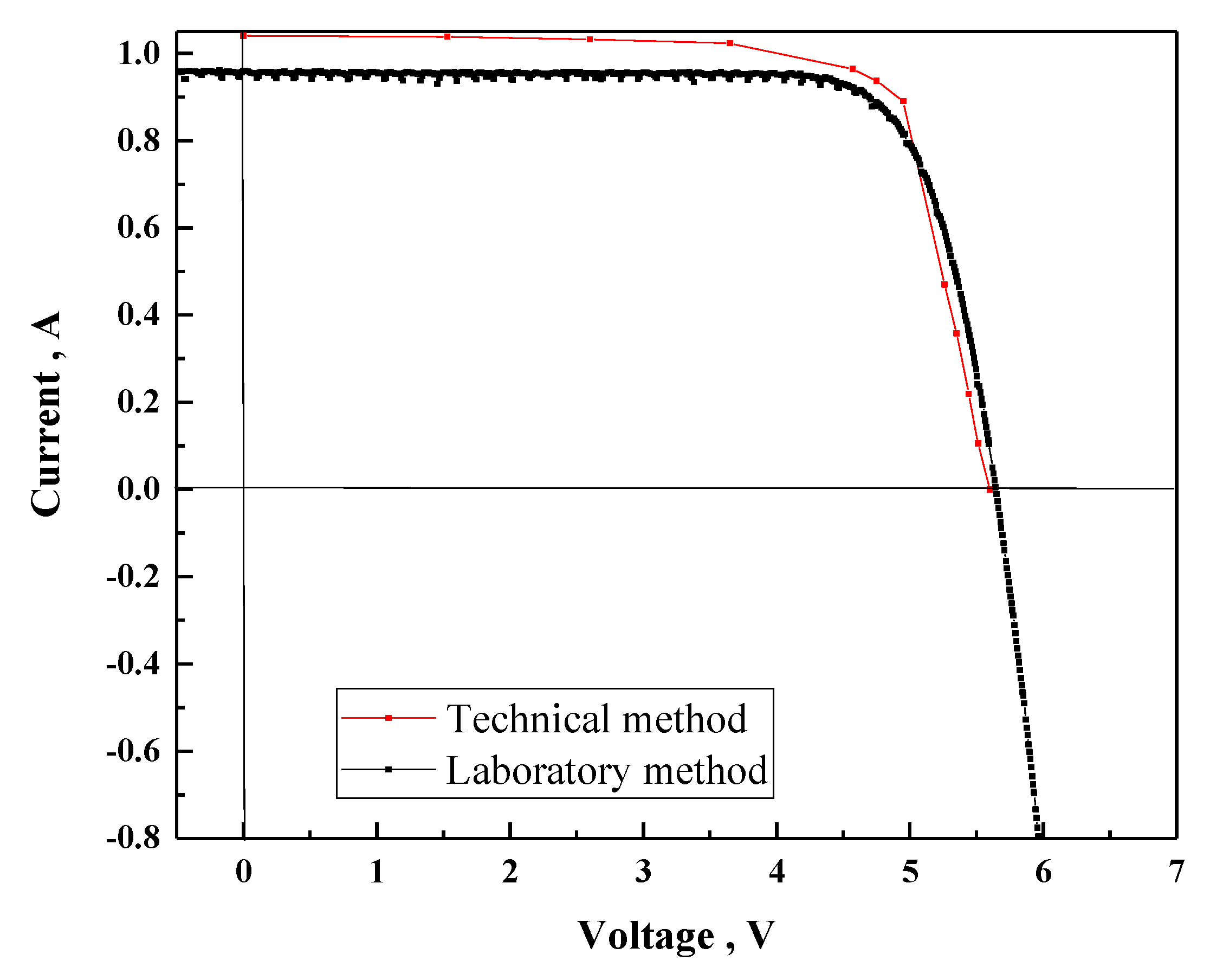
In order to characterize current-voltage characteristics of PV module, two different methodologies were employed: laboratory (current-voltage tracer model SC I-V CT-02 equipped with solar irradiation simulator model ST150AAA, PV Test Solutions, Wrocław, Poland) and technical (using home-made SOLARBOX sunlight simulator) method. In laboratory conditions, we were able to control the temperature around 25 °C—the temperature by the cooling system embedded in measuring table has higher accuracy (error lower than 1%).
On the other hand, the technical method has a lower accuracy (approx. 10%) than the laboratory method, but it is very fast, simple and cheap. Voltage and current measurements necessary to determine the current-voltage characteristics of the photovoltaic module were carried out by measuring voltage changes as a function of load change at constant light intensity of 1000 W/m
2 (
Figure 7). The measurements took place after the surface temperature of the photovoltaic module stabilized at around 25 °C. It is particularly important due to the large changes in potential barrier voltage—for silicon 2 mV/K.
In
Table 1, photovoltaic parameters of investigated new PV module recorded by laboratory and technical experiments are presented, showing quite good agreement between two different measuring methods.
The electrical parameters of investigated PV module in the laboratory setup were as follows: a short circuit current ISC of 0.96 A, open circuit voltage VOC of 5.6 V, and a fill factor FF of 78%, giving a power conversion efficiency PCE of 17.4%.
The laboratory method is a measurement using a A-class sunlight simulator. Spectrum of the simulator was recorded and compared to comply with the Class A tolerances, as specified in IEC 60904-9, ed. 2. The illumination power was 1000 W/m2. The applied measurement procedure is accredited by ILAC (International Laboratory Accreditation Cooperation). In the case of the technical method, a light source (home-made SOLARBOX sunlight simulator) was used, whose spectrum is similar to solar (AM1.5.) and the power is approximately 1000 W/m2. Comparing the results, it should be noted that the measured open-circuit voltage in both measurement systems is identical, while the differences relate to the value of the short-circuit current. This is due to the fact that the measurement of open-circuit voltage (of few volts range) is relatively simple and accurate, while the measurement of short-circuit current depends mainly on the real radiation power (and spectrum).
In the presented case, the values obtained during the laboratory measurement are certainly closer to reality. It is worth noting that, from the point of view of the proposed system, it is important to know the approximate range of the power and short-circuit current of the used solar battery. Using the proposed technical method, we can do this. The biggest advantage of this method is the measurement speed and the simple and cheap source of sunlight.
3.2. Performance of PV Module—LIB Device with Battery Management System
In search of the simplest converter construction, the converter was made of a transformer with two windings, in which the output circuit is also a feedback circuit, which will also provide voltage stabilization. The frequency of the inverter operation is determined by the capacitance of the C2 capacitor, the electrical parameters of the TR1 transformer, and the load value of the system. The tested system consists of the following elements: 1 Lithium ion battery, BMS (battery management system) and PV module as is presented in
Figure 1a. The electrical parameters of such a PV module—LIB device with Battery Management System (BMS) were measurement in laboratory conditions (using SOLARBOX sunlight simulator) and real conditions (full and clouded sun). During this measurement, an external BMS system located on the battery housing was used. The lighting intensity was changed from 500–1000 W/m
2, as is presented in
Table 2.
In real conditions for the PV module—LIB device with BMS under intensity about 250 W/m2 (clouded sun) gave a charging current approx. 0.21 A, while under full sun (about 920 W/m2) value of charging current increased to approx. 0.91 A. Moreover, it should be stressed that, under experiments, we received a value of real battery capacity equal of 2882 mAh by using BMS, which is in good agreement with the value declared by the manufacturer (2900 mAh).
To sum up, the research carried out in this part of our work fully confirms the concept of connecting a photovoltaic module with a lithium-ion battery through a protection system. Preliminary assumptions regarding the selection of the number of cells their size were also confirmed—the values of open circuit voltage and short-circuit current are correlated with the battery parameters.
3.3. Performance of PV Module—LIB Device with Step-Up Voltage Converters
In most cases, the voltage obtained from solar modules is significantly different from the battery voltage. Voltage converters (step-up or step-down) are then necessary. This study presents the results of research aimed at checking the possibility of combining a photovoltaic module and a lithium-ion battery with a step-up converter. The use of a voltage stabilizing converter between the solar cell and the lithium-ion battery can in some cases replace the power management system and battery protection. Generally, the voltage converter allows one to match the electrical energy requirements of receivers with electric current parameters from a power supply system, whose current-voltage parameters do not allow direct connection with the receiver. The converter’s task is to change the value of current and voltage in a way that meets the requirements of the powered receiver, with the lowest possible power loss increasing the conversion efficiency.
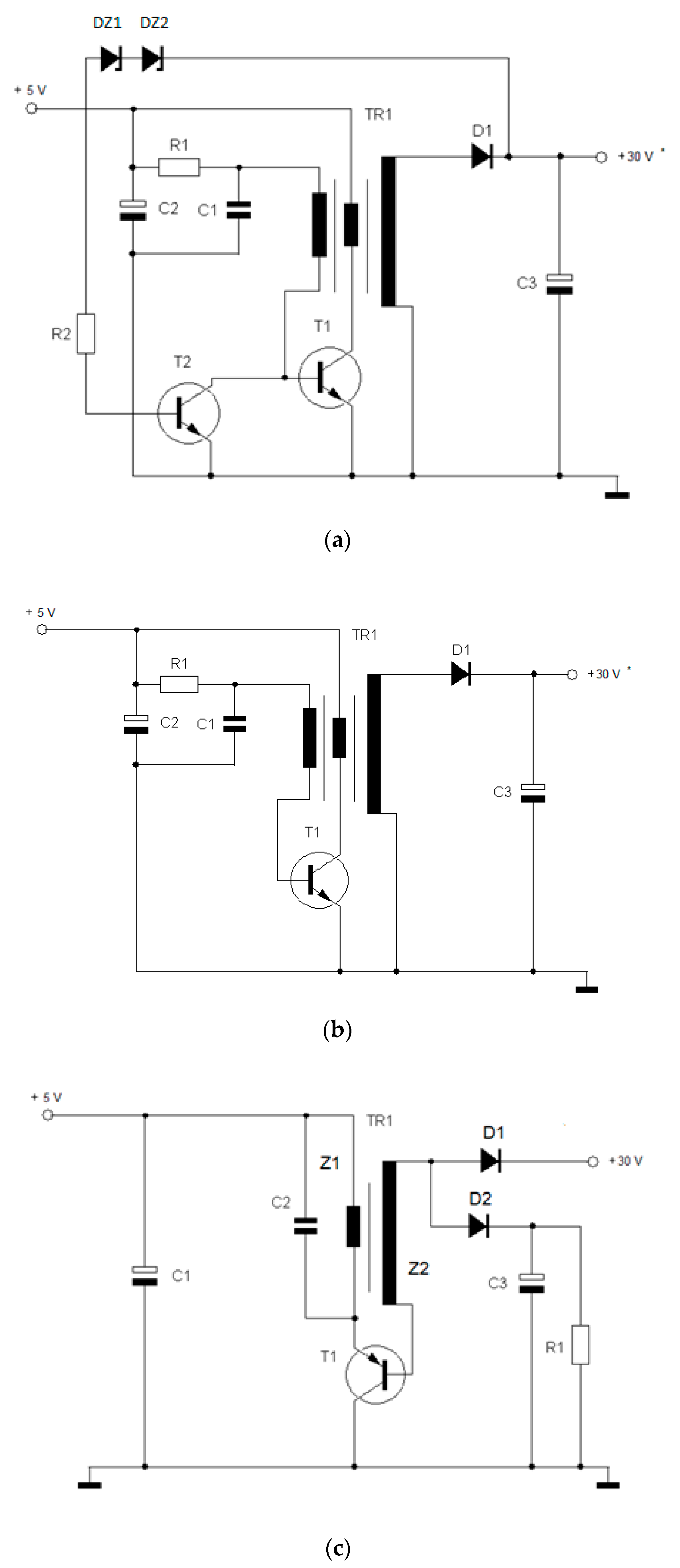
In the second step, we investigated a system consisting of a lithium-ion battery stack (42 pieces), a PV module and a step-up converter. In the case of the solution proposed in this paper, three types of step-up converters were tested. Input voltage about 5 V coming from solar module was used. Output voltage was up to a maximum of about 30 V, depending on how the lithium-ion battery bank was connected. In the first stage, the use of the commonly known system presented in
Figure 8 was considered (one of the typical applications). It is a step-up converter made in a system with a choke (energy storage system) and an electronic key (MOSFET transistor), a control system with a rectangular waveform generator (NE555 integrated circuit) and a stabilization system (feedback loop—T2 transistor). The system is characterized by good parameters, but due to the high degree of complexity, it is not recommended in the intended application. Looking for simpler solutions of the converter, we proposed to make it in the form of a transistor generator. The electrical systems of the analyzed converters are shown in
Figure 8a–c.
A testing system was made (
Figure 8a), which was tested using a 5 V power supply and an adjustable resistor as load. The obtained results are presented in
Table 3. The efficiency obtained for the step-up converter η = 0.69 is a good result, however, it was decided to make further simplifications of the system by removing the stabilization system. The scheme of obtained system is shown in
Figure 8b.
Simplification did not bring the expected results—the system was very unstable and the output voltage strongly depended on the size of the load. Such a result disqualified this solution.
Because we care about the simplicity of the design (the smallest number of elements), we reach for a generator system with two windings, in which the output circuit is also a feedback circuit, providing voltage stabilization. The schematic diagram of the “optimal” converter is shown in
Figure 8c. The processing efficiency was η = 0.76, and in our knowledge, it is a very good result for a step-up converter.
Charging current measurements in the PV module—LIB device with step-up voltage converters were performed in a laboratory using SOLARBOX sunlight simulator and real conditions (
Figure 1b). During this measurement, the external BMS system (which protects the battery) was not used—it was limited to the inverter, which had internal voltage stabilization (BMS systems are only security electronic keys, practically having no impact on the measurement results, due to the very low transition resistance). The measurements were made at an illuminance of approx. 1000 W/m
2. Obtained results are summarized in
Table 4. The results showed good processing efficiency of the PV module—LIB device with step-up voltage converters equal to about 0.71–0.75% in both laboratory and real conditions.

 and
and 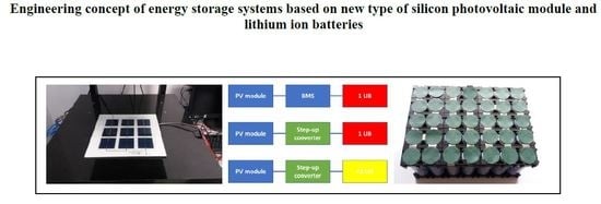


