1. Introduction
Power generation systems based on renewable energy sources, such as the solar photovoltaic (PV) and wind power plants (WPPs), present a non-dispatchable power generation characteristic. Furthermore, such systems are connected to the grid using power electronic inverters. As a consequence, operational issues, such as voltage instability and instabilities during faults, harmonic resonances and flicker, may appear [
1,
2]. Apart from providing fast and dynamic reactive power support for improving voltage regulation, static synchronous compensators (STATCOMs) play an important role in improving voltage stability. Moreover, STATCOMs provide the reactive current for low voltage ride through according to the relevant grid codes [
3].
The growth of large WPPs and PV power plants leads to the replacement of conventional power plants in the power systems. As these kinds of power plants cannot inherently respond to the frequency deviations, there is a reduction in the overall inertia and reserves for frequency control. Furthermore, the non-dispatchable nature of the wind and PV power implies that there is no black start capability.
Energy storage systems can provide the flexibility to the WPPs and PV plants to operate as dispatchable power plants. Therefore, battery energy storage systems (BESSs) are being developed and commissioned at the grid-level. Thus, the auxiliary services, such as inertial response, frequency control, spinning reserve, peak-load shaving and avoidance of power curtailment, are provided [
4]. An efficient and compact solution, which can respond to both the active and reactive power control requirements, can be provided if such a BESS can be integrated with a STATCOM [
5]. Such a STATCOM integrated with a battery for energy storage is referred as ES-STATCOM in [
2].
In the literature, some initiatives from industry toward developing ES-STATCOMs can be identified. ABB has installed an 850 kVA ES-STATCOM with a power rating of 200–600 kW and energy capacity of 200 kWh stored in Li-ion battery in Norfolk England [
6]. This system is based on neutral-point clamped (NPC) converter and the batteries are installed in the converter dc-link [
7]. On the other hand, Siemens has introduced the “SVC PLUS Frequency Stabilizer”, which can provide ±50 MW of active power for a few seconds for fast frequency response in addition to the reactive power of ±50 Mvar [
8]. This converter is a modular multilevel converter (MMC) STATCOM with super-capacitors. The relatively short response time is due to the super-capacitors. Ingeteam has installed a system in the Canary Islands which can provide ±4 MW of active power for up to 6 s and 2 Mvar continuously. This system is also based on super-capacitors [
9]. These initiatives from companies highlight the interest of industry to develop ES-STATCOMs and introduce them in the market.
Modular multilevel converters (MMCs) are a promising family for the implementation of ES-STATCOM, since MMC topologies are modular and scalable to medium voltage and high voltage levels necessary for high power rating in the grid applications [
4,
10]. The concept of MMC is based on the cascaded connection of low voltage units (known as cells or submodules) to build a high voltage converter. In addition, there are advantages of inherent fault tolerance, high efficiency and low harmonic distortion [
11]. The MMC family can be classified in the following topologies:
Single-star bridge cell (SSBC);
Single-delta bridge cell (SDBC);
Double-star chopper cell (DSCC);
Double-star bridge cell (DSBC);
Double-star hybrid cell (DSHC).
The last topology is included in the classification proposed by [
12]. In contrast to other multilevel topologies, all MMC family members allow the distribution of energy storage units among the converter cells. Additionally, the double-star topologies present dc-link terminals necessary for the connection of centralized energy storage systems.
There are many articles in the literature that compare the MMC family for different applications. For instance, in [
13] DSCC, DSBC and DSHC for high-voltage direct current (HVDC) systems are compared. DSHC presented the best performance in terms of power losses and dc short-circuit handling capability. Amorin et al. analyzed the use of DSCC and DSBC in variable-speed ac drives [
14]. DSBC presented less voltage ripple in the low-speed region. Behrouzian and Massimo have compared the performances of SSBC and SDBC topologies for STATCOM while injecting negative sequence components [
15]. It was concluded that SSBC and SDBC have limited operational ranges during unbalanced grid conditions due to singularity in the computation of the zero-sequence component (current in the case of SDBC, and voltage in the case of SSBC) for equal distribution of power sharing among the phase legs. Recently, the performances of different MMC topologies for STATCOM realization have been compared in [
16,
17]. It was concluded that DSCC does not present any such limitation.
Regarding the ES-STATCOM realization, the economic benefits of the multifunctional operation of ES-STATCOMs in offshore WPPs have been discussed in [
18]. Hillers et al. compared SSBC, SDBC and DSCC topologies with respect to efficiency, silicon area and converter volume [
10]. However, only the distributed energy storage (DES) approach has been considered. Baruschka and Mertens compare SSBC and DSCC with centralized energy storage (CES) with dc/dc converters to connect the battery bank to the dc-link [
19]. However, in these references the converter is only exchanging active power with the grid, which is not the case for an ES-STATCOM.
It is argued in some papers that the cell current ripple can decrease the lifetimes of the batteries [
10]. Puranik et al. has experimentally demonstrated that the ripple currents degrade the lifetime of the battery [
20]. Baruschka and Mertens have concluded that the dc-link voltage gets decoupled from the battery voltage variation by the dc/dc converter, and hence the voltage rating of the converter can be optimized [
21]. Cao et al. compared the CES and DES approaches of connecting the BESS to the MMC converters, viz., in the cell as distributed energy [
19].
Other works used the cascaded topologies without the dc/dc stage; i.e., the batteries were directly connected to the converter cells. Zhang et al. has described the operation and control of an MMC with BESS without any intermediate dc/dc converter interface [
22]. Li et al. avoids the need for dc-dc converter but uses the PWM strategy to account for the differences in the voltages of the individual battery packs due to variations [
23]. Zhang et al. describes a virtual synchronous generator using an MMC BESS system without any dc/dc converter interface [
24]. Gao et al. have commented that employing the dc/dc converter interface between the battery pack and the converter will increase the cost and complexity, and hence they directly connected the BESS to the MMC cells [
25]. This strategy will need more sub-modules in the MMC to account for the battery voltage variations and the ripple current through the battery cannot be avoided.
Although there are several benefits of MMC family for ES-STATCOM realization, there is so far no commercially available MMC-based ES-STATCOM that utilizes batteries. Moreover, there is a lack of the technical literature discussing the design and the comparison of MMC-based ES-STATCOMs. Indeed, there is no technical reference indicating the most suitable MMC topology for ES-STATCOM realization. This paper benchmarks different MMC-based ES-STATCOM topologies. Both centralized and distributed energy storage approaches are considered. The proposed design flowcharts can be employed for comparison and optimization purposes. In total, seven topologies are compared in terms of number of cells, required silicon area and total battery volume. Different semiconductor devices and battery types are analyzed. The most suitable topology for ES-STATCOM realization is determined.
The rest of this paper is outlined as follows.
Section 2 presents seven different ES-STATCOM topologies evaluated in this work. The design flowcharts are presented in
Section 3. The case study parameters and the battery types together with the semiconductor devices are presented in
Section 4.
Section 5 shows the results. A discussion of the results and the selection of the most suitable MMC topology is presented in
Section 6. Finally, the work is concluded in
Section 7.
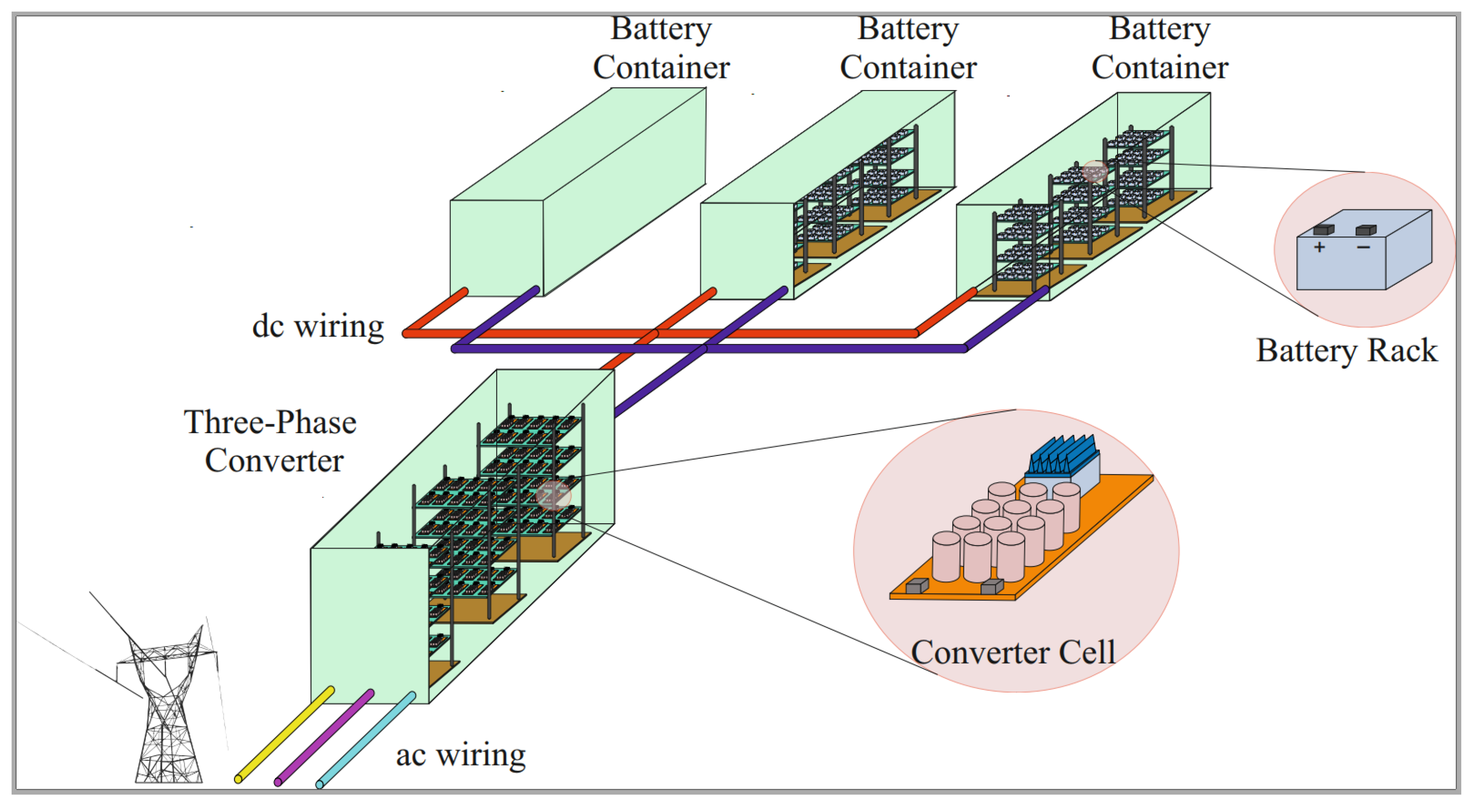
2. MMC-Based ES-STATCOM
In total, seven different topologies of MMC-based ES-STATCOM are analyzed in this work. As previously mentioned, either centralized or decentralized approaches can be employed.
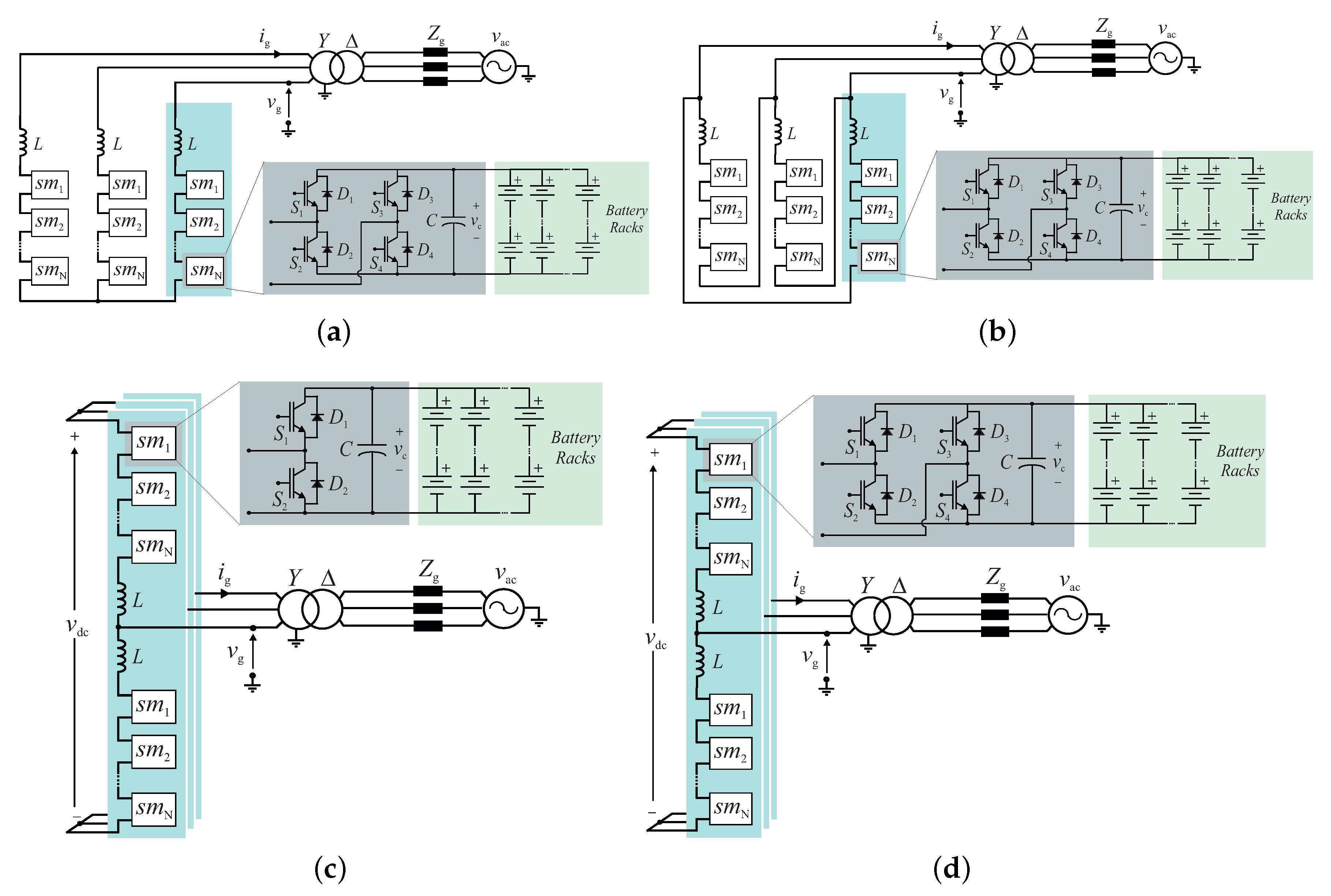
Figure 1a presents the schematic of SSBC-DES. This topology presents three clusters of bridge cells in a single star-connection. The converter presents N cells per cluster with the capacitance C. The cluster inductance L filters the output current. In this topology the state-of-charge (SOC) balancing among the clusters is performed by controlling zero-sequence voltage injection [
26]. The individual balancing strategy depends on the modulation scheme employed [
27].
Figure 1b presents the schematic of SDBC-DES. This topology presents three clusters of bridge cells in a delta-connection. The converter presents N cells per cluster with the capacitance C. This topology presents a zero-sequence current (or circulating current) which circulates inside the delta connection. The cluster inductance L smooths the output current and the circulating current. The SOC balancing among the clusters is performed by a circulating current control, as discussed in [
28].
Figure 1c,d presents the schematics of DSCC-DES and DSBC-DES topologies, respectively. These topologies comprise of six arms. The converter presents N cells per arm. Each cell presents a capacitance C. Since the dc-link connection is not used in DES systems, this topology presents two independent circulating currents. The arm inductance L attenuates the harmonics in the converter circulating current. The SOC balancing is performed by a circulating current control [
29]. Although the control strategy is very similar for DSCC-DES and for DSBC-DES, the modulation schemes, power losses and design methodologies are quite different, as will be discussed in the next sections.
The advantages of DES approach are related to the use of low-voltage battery packs, which simplifies the design. In addition, if a failure is detected in one battery rack, it can be isolated from the main circuit. Thus, only the energy storage in the faulty cell is lost. However, the DES approach presents some drawbacks. Firstly, the integration of batteries in the converter cell leads to some thermal management issues. The converter enclosure usually has a higher temperature than that recommended for batteries. Therefore, the integration can reduce battery lifetime or increase the cost and complexity of the cooling system. Secondly, if the batteries are not integrated in the converter cells, but installed in a different containers, the number of dc-cables may be massive (two cables per converter cell). Finally, when the battery pack is located close to the converter cell, the maintenance is more difficult.
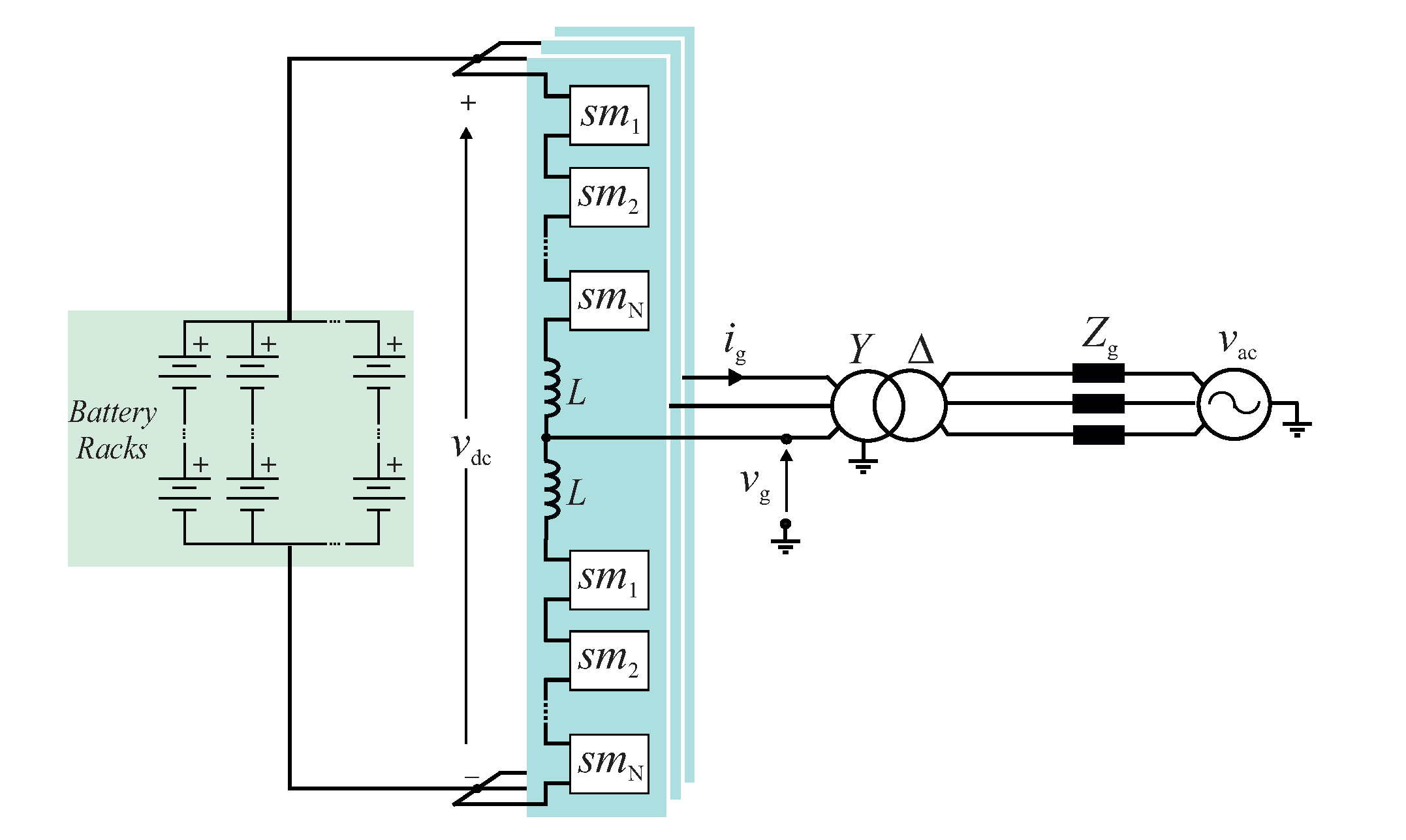
Figure 2 presents the schematic of the CES topologies. DSCC-CES, DSBC-CES and DSHC-CES topologies differ only in the type of cell employed. In the CES approach, the battery units are concentrated in the dc-link. Hence, the converter cannot perform the SOC balancing among different battery cells and traditional approaches, as passive balancing or bypass structures must be included in the battery units [
30]. Only the global SOC can be controlled by the converter. The capacitor voltage balancing is performed by circulating current control, as discussed in [
27]. The main differences in DSCC-CES, DSBC-CES and DSHC-CES are related to modulation schemes, power losses and design methodologies. For example, the DSHC-CES topology replaces some bridge cells by chopper cells to increase the overall efficiency and to reduce the total cost of the converter.
As noticed, the batteries can be installed in a separate container in the CES approach. Therefore, a temperature control to maximize the battery lifetime can be implemented. Furthermore, the ES-STATCOM can operate as a conventional STATCOM when batteries are isolated for maintenance. The first drawback is that the isolation of batteries for maintenance requires a dc disconnector. In addition, the batteries must be designed to operate at high voltage. Finally, a dc breaker is required for dc-link short-circuit protection.
3. ES-STATCOM Design Methodology
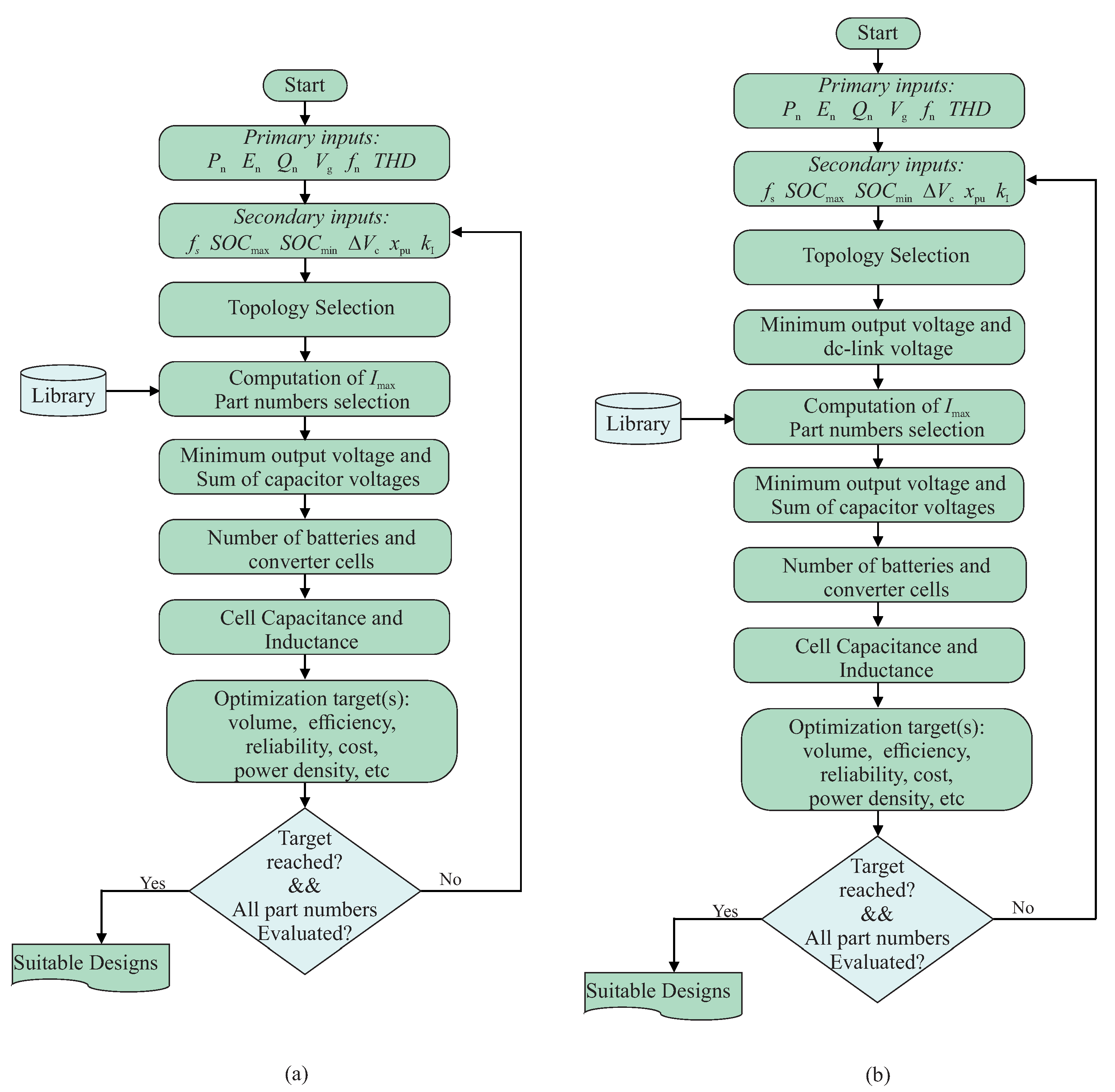
As previously mentioned, this paper proposes a flowchart for design and optimization of ES-STATCOM systems. These flowcharts are illustrated in
Figure 3a,b, respectively. Firstly, the primary and secondary input parameters must be defined. The primary input parameters are defined on the basis of the ES-STATCOM nominal specifications. For the adopted case study, the parameters are given in
Table 1. The secondary input parameters can be adjusted to reach some optimization target. For example, the minimum acceptable
influences both the ES-STATCOM efficiency and volume, and the batteries’ lifetime. Therefore, for given lifetime or volume targets, the
can be varied to obtain the optimum solution (best efficiency, optimum volume, etc.). Often, trade-offs must be defined: e.g., the higher the
, the higher the batteries’ lifetime and the higher the volume.
The design methodology presented in this paper is based on the following assumptions:
Internal power losses in the battery storage are neglected for simplification;
Three-phase grid voltages are assumed balanced and sinusoidal;
Arm/cluster inductances are determined for each topology to guarantee the same per unit value for the grid current, and therefore, the same filtering capability;
Rated current of inductors is determined by neglecting the switching harmonics;
Converter capacitance is based on the energy storage requirement for 10% voltage ripple at rated conditions;
The same C-rate is assumed during the charging and discharging process of the battery. (C-rate is a measure of the rate at which a battery is charged/discharged relative to its maximum capacity. For example, if the capacity of a battery is 100 Ah and the maximum assumed C-rate is 0.5, it means that the battery is charged/discharged with a maximum current of 50 A.)
Since DES and CES presents their own design characteristics, their design flowcharts are described in different subsections.
3.1. Decentralized Energy Storage Topologies (DES)
After the selection of primary and secondary inputs, the second step in the DES system design is to select the desired converter topology in
Figure 1. The peak current
in the converter arms/clusters are an initial parameter to determine the semiconductors and inductors current rating.
Considering balanced grid conditions, the peak current in the converter arms/clusters is given by [
16]:
where
is the peak of the converter output current.
The rated current of the semiconductor device
can be determined as:
where
is the current sizing factor. Its value depends on:
Device temperature, which is function of losses and cooling;
Modulation strategy, switching frequency and dc-link voltage, which affect the power losses;
Topology, which affects the average and rms current in the semiconductor devices.
To the best of the authors’ knowledge, there is no technical reference describing typical
values for MMCs. However, most references employ
[
21,
31,
32]. This means that the IGBT rated current is usually higher than the maximum of the arm/cluster current. Using
, a suitable semiconductor device can be selected.
The next step is to determine the required output voltage for the grid connection. Assuming rated (i.e., 1 pu) capacitive output currents from the converter to the grid, the peak of line-to-neutral voltage at the converter output
is the sum of grid voltage and the voltage drop in the equivalent output inductance. Accordingly,
where
is the peak of the line-to-neutral voltage,
is the maximum ac grid voltage variation in pu and
is the per unit equivalent output reactance of the converter. One pu inductive output current is assumed (
). As observed, a 5% margin is considered to guarantee a suitable dynamic behavior in the current control [
4].
The ES-STATCOM must be able to synthesize
given by (
3) in the linear region of the modulator. The sum of capacitor voltages
is determined as a function of
. The relation between
and
is dependent on the topology and the modulation strategy (e.g., if zero-sequence injection is taken into account). The required sum of capacitor voltages of each arm/cluster in the different topologies, when sinusoidal pulse width modulation (SPWM) is employed, is given by,
On the other hand, the zero-sequence voltage injection is possible in the ES-STATCOM realizations based on DSCC-DES and DSBC-DES. This approach can extend the modulator linear region. However, this idea is not applicable to SSBC-DES and SDBC-DES, since SDBC-DES has a path for zero-sequence current circulation and SSBC-DES employs the zero-sequence voltage for the capacitor voltage/SOC balancing [
12]. Considering 1/6 third harmonic injection in DSCC-DES and DSBC-DES [
33], relation (
4) gets modified as follows:
As observed in (
5), SDBC-DES needs a higher
than SSBC-DES since each cluster must handle the line-to-line voltages. Both DSCC-DES and SDBC-DES require the same sum of capacitor voltages when the third-harmonic injection is taken into account. The DSBC-DES has the lowest voltage requirement. Although DSCC-DES topology presents a pole-to-pole dc-link voltage
,
is usually adopted. On the other hand, the dc-link voltage for DSBC-DES is zero (i.e.
to minimize the number of required cells for this topology [
17].
The number of series-connected batteries
for all DES topologies is determined by:
where
is the maximum battery voltage (function of the maximum allowed state-of-charge
) and
is the nominal cell voltage. Usually,
is selected as the IGBT voltage corresponding to 100 FIT (100 failures in
operating hours) [
34].
The number of cells per arm/cluster is given by:
where
is the minimum battery voltage (function of the minimum allowed state-of-charge
). For SSBC-DES, SDBC-DES or DSBC-DES, the number of bridge cells is given as
. For DSCC-DES, the number of chopper cells is given as
.
The total number of battery racks in the converter must fulfill two requirements: the energy requirement
and the active power requirement
. The number of parallel-connected battery strings per converter cell is given by [
35]:
where
is the nominal energy storage capacity of each battery,
is the battery capacity and
is the maximum recommended C-rate by the manufacturer.
On the other hand, since the ES-STATCOM converter must operate even if the batteries are not available, the design of the cell capacitance is accomplished considering a standard STATCOM. Under such conditions, the cell capacitance can be determined by [
33]:
where
is the energy storage requirement in kJ/MVA. Considering a 10% ripple criterion,
= 40 kJ/MVA for cell capacitance in DSCC-DES;
= 20 kJ/MVA is employed for bridge cell based topologies [
17,
33].
The arm/cluster inductances are determined for each topology to guarantee the same per unit reactance for the grid current filtering. Therefore, the converter topology directly affects the inductance value and its current rating. Assuming the same per unit value
, the arm/cluster inductances are determined as:
3.2. Centralized Energy Storage (CES)
For DSCC-DES, the required sums of capacitor voltages and dc-link voltage are usually the same. DSFB-CES and DSHC-CES present different voltage requirements. The bridge cells can generate both positive and negative voltages, allowing over-modulation, as described in [
36]. Therefore, considering sinusoidal modulation, the required dc-link voltage
is given by:
where
is introduced as the desired reduction in the dc-link allowed by the over-modulation.
On the other hand, if 1/6 of third harmonic injection is considered, the required dc-link voltage is given by:
The arm currents include an ac and a dc component in the CES topologies. Therefore, the maximum current is expected to be higher than the one obtained by (
1). The maximum current in the arm inductors (and the maximum reachable current in the semiconductor devices in each cell) for all centralized topologies is given by [
27]:
where
is the peak of the converter output current,
is the nominal active power and
is given by (
11) or (
12). Hence, there is an increase in the converter arm current when the dc-link voltage is reduced in both DSBC-CES and DSHC-DES. This can lead to a higher current rating of these topologies compared to DSCC-CES and all DES topologies. It is worth remarking that CES topologies require semiconductor devices and inductors with higher current rating.
For the DSCC-CES topology, the total number of series-connected battery racks
can be determined by:
For DSBC-CES and DSHC-CES topologies, the output voltage is not limited by the dc-link voltage [
14]. Thanks to the bridge cells, the converter can handle dc-link voltage variations. Under such conditions, the total number of series-connected battery units
can be computed by:
Then, the total number of parallel-connected battery strings given by Equation (
8). The number of chopper cells in DSCC-CES is given by:
The number of bridge cells in DSBC-CES is given by:
where
is the over-modulation factor.
Finally, for the DSHC-CES topology, the numbers of bridge cells and chopper cells are determined as described in [
36]. The number of bridge cells in DSHC-CES depends on two factors: (1) the number of bridge cells required to reach the over-modulation factor; (2) the number of bridge cells which guarantees the capacitor voltage balancing. Accordingly:
where
is the minimum dc-link voltage. For an ES-STATCOM, this value can be determined as follows:
The passive components are designed based on Equations (
9) and (
10). It is important to remark that
= 40 kJ/MVA for cell capacitance in chopper cells, while
= 20 kJ/MVA was employed for bridge cells. In addition, the inductors of CES topologies present a higher current rating than DES topologies.
At this point, the following conclusions can be stated:
DSCC-CES design depends on both maximum and minimum battery voltage. Therefore, the converter silicon area and the batteries’ volume are strongly dependent on the allowed SOC range.
DSBC-CES design does not depend on the minimum battery voltage, as the bridge cells can generate both positive and negative voltage. This property can extend the converter operation for low dc-link voltages [
27].
DSHC-CES topology also improves the performance of DSCC-CES topology. Furthermore, it reduces the ES-STATCOM cost when comparing to DSBC-CES, since bridge cells are 30–50% more expensive than chopper cells [
36].
The performance of DSBC-CES and DSHC-CES topologies is affected by the over-modulation factor. This degree of freedom can be used to optimize the converter (e.g., minimize the converter silicon area).
The over-modulation factor is used to reduce the required dc-link voltage and to reduce the number of series-connected battery units.
3.3. Optimization
After determining the main circuit parameters, the power converter design for both DES and CES approaches can be optimized. The optimized variables depend of the application and the final user objectives. Examples of common optimization variables are efficiency, volume, power density, batteries/converter lifetime and/or cost.
Different methodologies that are presented in the literature can be used to evaluate the target variables. A methodology to estimate the converter indirectly based on the silicon area is presented in [
31]. Bortis, Neumayr and Kolar present methodologies for volume and efficiency in power converters in [
37]. Moreover, different semiconductor devices can be evaluated. For example, different IGBT part numbers with different current rating and blocking voltage can be evaluated. If the target is not reached for the selected part numbers, the secondary inputs can be modified. In general, an iterative process computes the most suitable design for the selected topology. For example, for DES topologies the factor
could be increased (i.e., increase of the IGBT current rating) and the performance in terms of efficiency and cost can be evaluated. For CES topologies, the factor
has an important role in the IGBTs current rating and converter efficiency. As observed, the flowcharts presented in
Figure 3 include many possibilities for multi-objective optimization.
In this paper, the total volume of batteries and the converter silicon area are used as figures of merit to select the most suitable design for the DES topologies, because they provide an indirect cost estimation. For CES topologies, the factor is varied to identify the most suitable design. The effect of the allowed range for the battery SOC is also evaluated. Finally, the practicability of the ES-STATCOM realizations is discussed.
4. Case Studies and Figures of Merit
The input parameters for the ES-STATCOM design are presented in
Table 1. Different part numbers are analyzed. Regarding the battery part numbers, Samsung LIBs from the Samsung SDI series are evaluated [
38]. The main characteristics of thirteen different types of batteries are summarized in
Table 2.
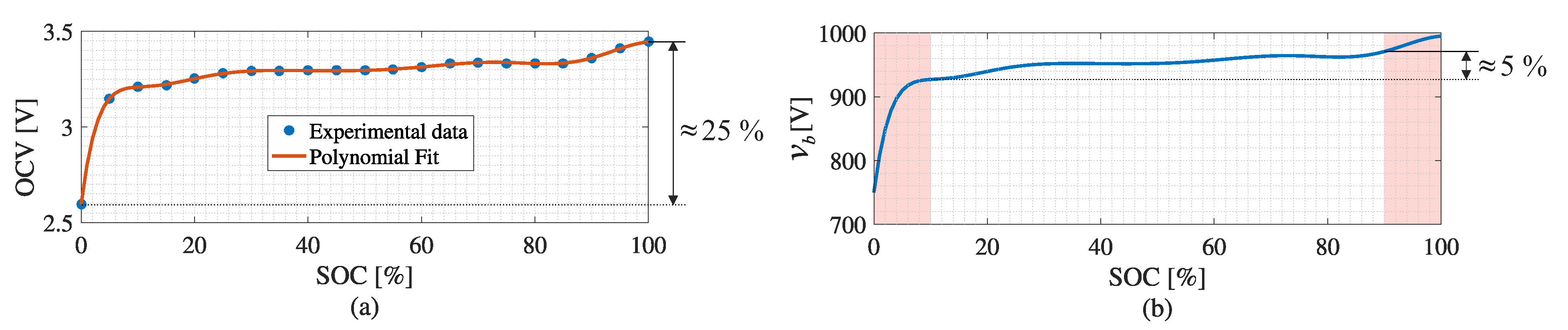
The open-circuit voltage (OCV) characteristic of a single LIB cell as a function of the SOC is presented in
Figure 4a. This curve was estimated based on curve fitting of experimental results for a single LiFePO
4 LIB from [
39]. An adaptive method for parameters estimation in LIBs is presented in [
40]. Different reduced-order models for LIBs are discussed in [
41]. In this paper, the experimental data of
Figure 4a were scaled up using the parameters of
Table 2. The estimated curve for case study 11 (part number P3-R070 from
Table 2) is presented in
Figure 4b. The highlighted regions indicate the adopted range for
and
in the ES-STATCOM design. As observed, when the range from 0% to 100% is adopted, the LIB voltage varies by 25% depending on the SOC. Moreover, when the range from 10% to 90% is adopted, the LIB voltage varies by 5%. Finally, the voltage variation is more sensitive to
than to
.
Regarding the semiconductor devices, ABB IGBTs from the StakPak series are evaluated [
42]. These devices are press-pack IGBTs. The main characteristics are summarized in
Table 3. As observed, five part numbers are evaluated. The voltages corresponding to 100 FIT values were obtained from [
43].
The ES-STATCOM topologies are compared based on different figures of merit. The total volume of batteries
is determined neglecting the creepage and clearance requirements. Accordingly:
The total silicon area employed in the converter is indirectly measured based on the converter ampacity (
). This figure of merit consists of the product of the number of power semiconductors and the rated currents of the devices. Accordingly,
where the constants 12 and 24 are found considering the total number of semiconductor switches in the whole MMC.
Finally, the utilization factor
is defined as follows:
The utilization factor is a figure of merit which measures the utilization of the semiconductor devices maximum rating.
5. Results
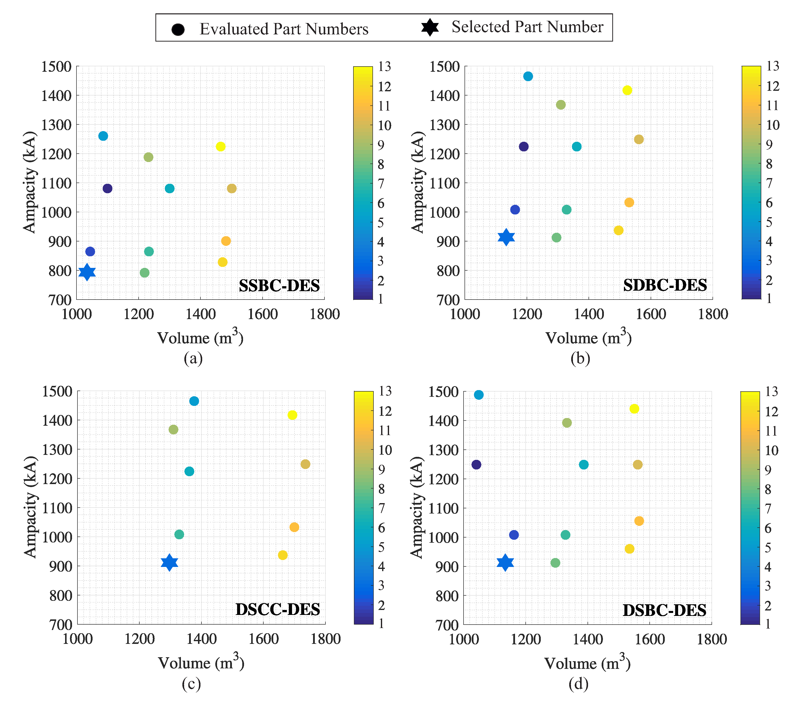
Initially, considering the SOC variation from 0% to 100%, the DES topologies were designed.
Figure 5 presents the ampacity versus volume map for the DES topologies. Since the system requires a high value of energy storage (for providing rated power for 3 h, according to
Table 1), the batteries classified as energy type (case studies 1–5) resulted in the lowest volumes.
Moreover, the converter ampacity (and the required silicon area) for DES topologies is strongly affected by the LIB part number. This fact is observed because the number of cells is directly influenced by the maximum and minimum LIB voltage in DES topologies. Case study 3 is selected, since this part number leads to a trade-off between total batteries’ volume and converter ampacity. The main parameters of the selected designs are summarized in
Table 4.
The individual analysis of
Table 4 reveals that SSBC-DES results in the lowest converter ampacity and volume. The main cause is the required number of converter cells for the same grid voltage, which is minimum for the SSBC-DES topology. It is important to remark that the topologies do not employ the same IGBT part numbers, due to the different current requirements. Moreover, the volume and ampacity are affected by the rounding in Equations (
6)–(
8).
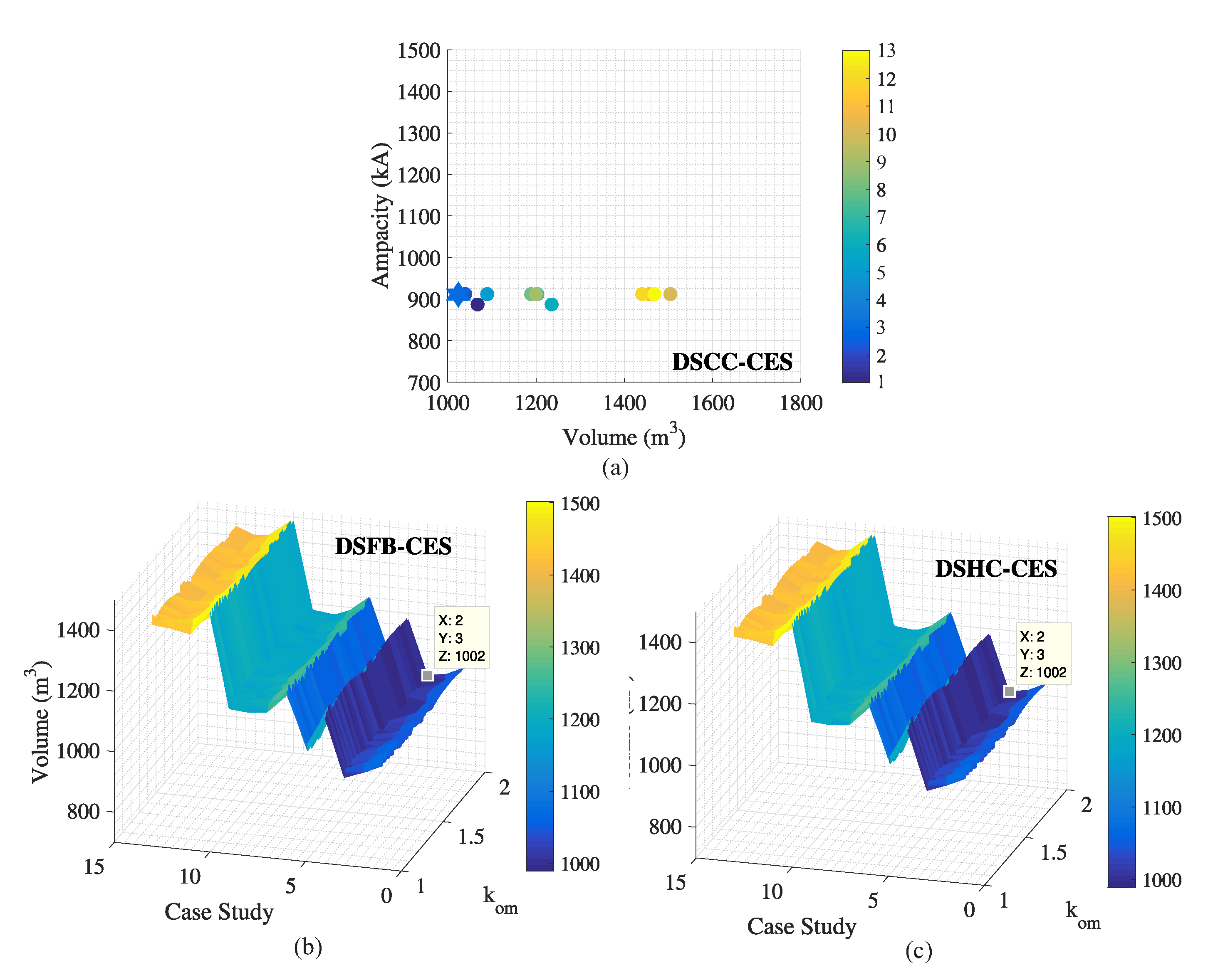
Then, CES topologies were designed considering the SOC variation from 0% to 100%. The obtained results are presented in
Figure 6.
Figure 6a presents the ampacity versus volume map for DSCC-CES topology. As observed, for CES topologies, the ampacity is not sensitive to the LIB part number. Therefore, the volume is used as figure of merit. The case study 3 is selected.
Since DSBC-CES and DSHC-CES present another degree of freedom (the over-modulation factor
), they require a careful analysis. A sensitivity analysis revealed that the volume is more sensitive to the LIB part number while the ampacity is more sensitive to the over-modulation factor. Therefore, the LIB part number is chosen to optimize the volume.
Figure 6b,c present the LIB volume as a function of the over-modulation factor and LIB part number. As observed, the case study 3 results in the minimum volume, independent of the over-modulation factor adopted.
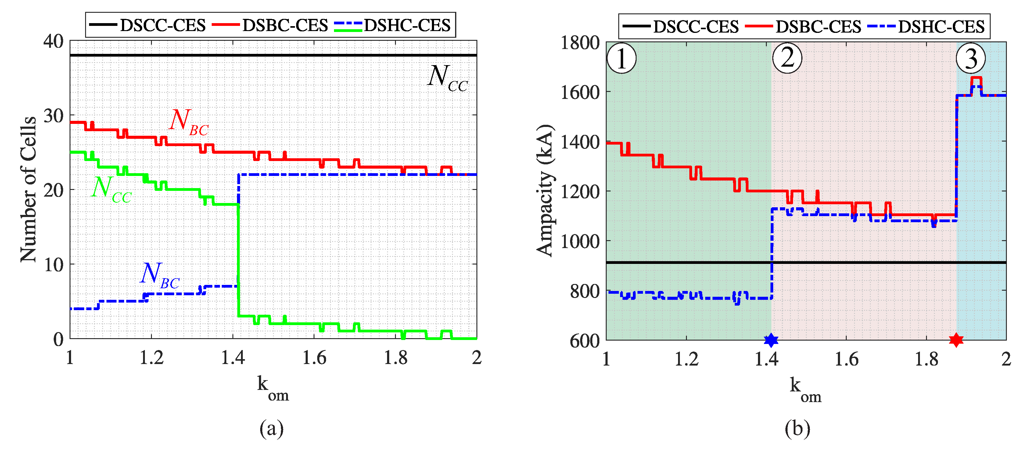
Figure 7 presents the effect of the over-modulation factor in the DSBC-CES and DSHC-CES topologies for case study 3. The results for DSCC-CES are presented for comparison purposes.
Figure 7a presents the number of cells. The numbers of cells of DSBC-CES and DSHC-CES are lower than the number of cells of DSCC-CES, because DSBC-CES and DSHC-CES topologies are designed for the maximum LIB voltage. The operation in the minimum voltage is guaranteed by the use of bridge cells, which generate negative voltage and reduce the required dc-link voltage.
When
increases, the dc-link voltage reduces and the number of bridge cells in DSBC-CES reduces. For DSHC-CES, an opposite behavior is observed. Indeed, when the dc-link voltage reduces, more bridge cells are required. Then,
reduces while
increases in DSHC-CES. However, the sum
is always equal to the number of bridge cells in DSBC-CES; i.e., the chopper cells are replaced by bridge cells when
increases. When
,
increases fast to guarantee the capacitor voltage balancing. Both DSBC-CES and DSHC-CES reach the same number of cells when
. The step is explained by Equations (
18)–(
20). The condition
can be rewritten as:
Figure 7b presents the ampacity of the CES topologies as a function of
. Three main regions can be identified. In region 1, DSHC-CES presents lower ampacity than DSCC-CES; i.e., DSHC-CES requires the lowest silicon area. This region ends when
. In region 2, DSCC-CES requires the lowest silicon area. The existence of the region 3 depends on the current rating of the available semiconductors. Indeed, when
increases, the dc-link current increases. This fact leads to higher current requirements according to the relation (
13). Therefore, at some point, the current capability of the IGBTs must increase. This fact leads to a step in the converter ampacity.
The optimum design is selected based on the minimum ampacity and minimum dc-link voltage. The latter simplifies the dc-link protections required in CES topologies.
Figure 7b indicates that the optimum value of
for DSBC-CES topology is
. For DSHC-CES,
is adopted. Using these values, the parameters presented in
Table 5 are obtained. As shown in
Table 5, the utilization factor for DSBC-CES for the selected design is approximately 0.5, since the current rating is equal to the semiconductor device current and
.
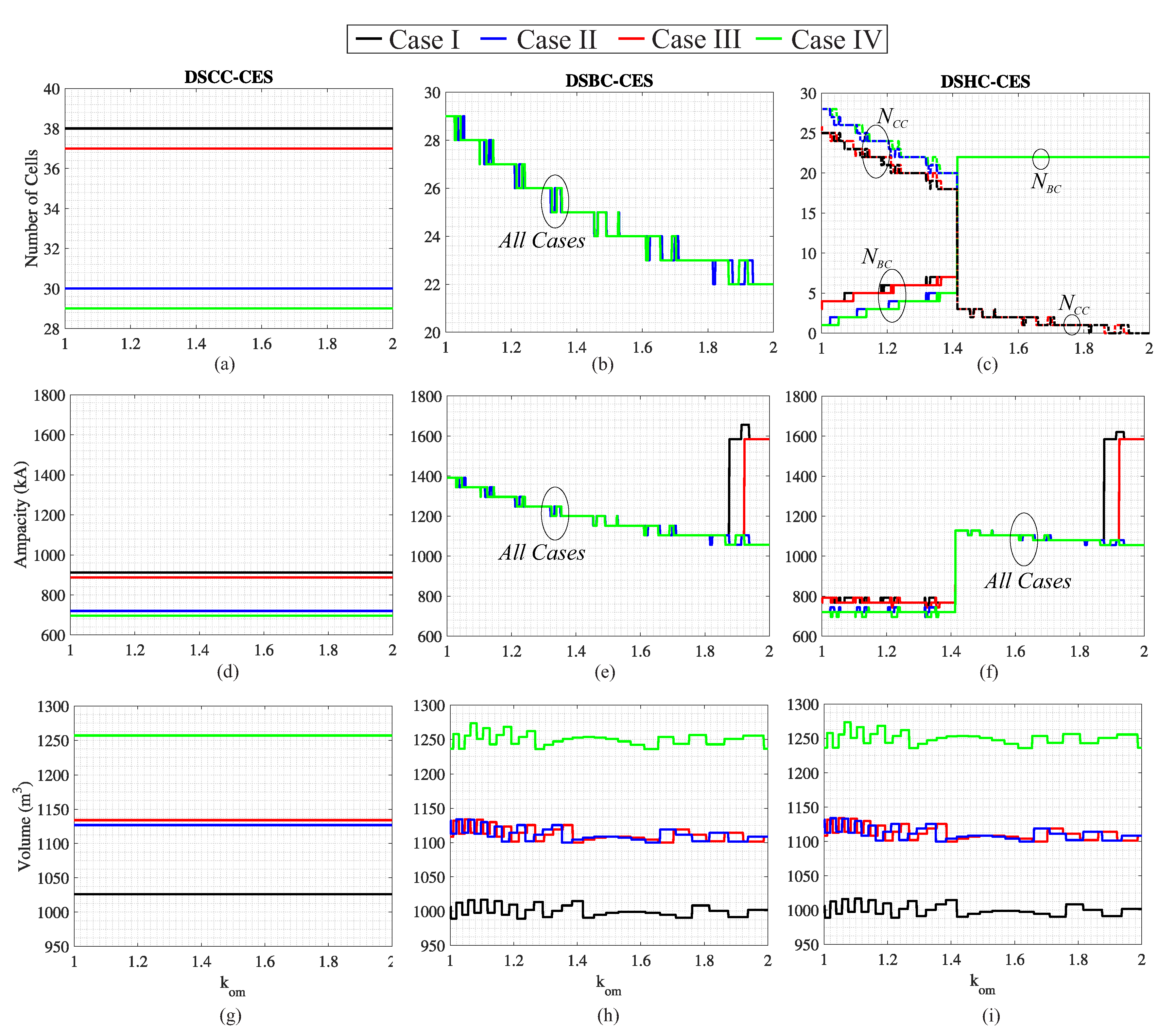
Finally, the effects of the maximum and minimum SOC limits upon the ES-STATCOM parameters are evaluated for different values of
and presented in
Figure 8. The following cases are considered:
Case I: = 0% and = 100%;
Case II: = 10% and = 100%;
Case III: = 0% and = 90%;
Case IV: = 10% and = 90%.
Figure 8a shows that both
and
affects the number of cells for DSCC-CES. The effect of
is more significant, since the LIB voltage is more sensitive to
, as shown in
Figure 4. As observed in
Figure 8b, DSBC-CES is not sensitive to
, since the converter is able to handle the voltage variation in the dc-link. In addition,
does not affect significantly the number of cells. For DSHC-CES, the results are presented in
Figure 8c. As observed, the effect of
is more important, since the lower the operating voltage, the higher the required number of bridge cells.
The ampacity is presented in
Figure 8d–f. As observed, the ampacity behavior is quite similar to the number of cells. It must be remarked that the optimum design point for DSBC-CES is a function of the allowed SOC range, as shown in
Figure 8e. The batteries’ volume is presented in
Figure 8g–i. As observed, the lower the SOC range, the higher the batteries’ volume. The differences observed in DSBC-CES and DSHC-CES as a function of
are justified by rounding.
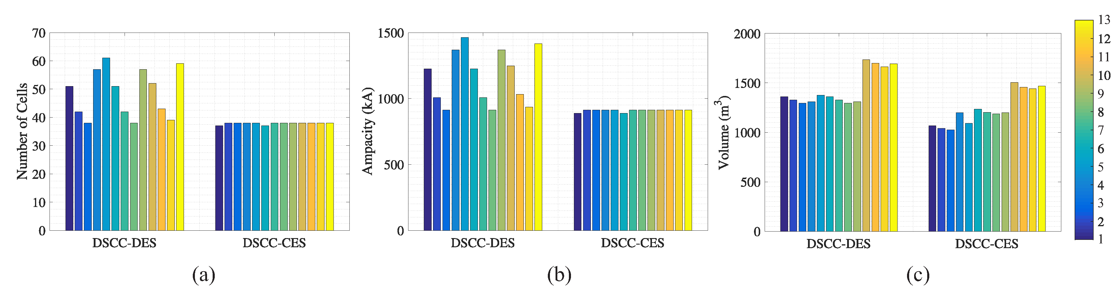
At this point, an important task is to select the best approach for ES-STATCOM application—DES or CES. In order to complete that task, DSCC-DES and DSCC-CES topologies are chosen, which leads to a fair comparison (same topology, different integration approach).
Figure 9 compares the number of cells, the ampacity and the volume for DSCC-DES and DSCC-CES. As observed, the DES approach is very sensitive to the LIB part number due to the rounding functions. This fact leads to a significant variation in the ES-STATCOM number of cells. As noticed, the DES approach can lead up to 55% higher ampacity and 30% higher volume. This results indicate an important advantage of CES systems.
7. Conclusions
This paper presented the design and comparison of seven topologies for ES-STATCOM realization based on modular multilevel converters. A comprehensive design flowchart was proposed. Different LIB part numbers were evaluated. Depending on the adopted battery part number, variations up to 70% in the required silicon area were observed for DES topologies. A comparison between DSCC-DES and DSCC-CES topologies showed that DSCC-DES led to 55% higher ampacity and 30% higher volume than the DSCC-CES.
The results also indicated that the over-modulation factor, , plays an important role in the optimization of CES systems. For DSHC-CES, the minimum converter ampacity was obtained when . For DSBC-CES, the optimum value of depends on the current rating of the evaluated power semiconductors. DSHC-CES and DSBC-CES also showed a low sensitivity to the SOC range adopted in the design. In addition, these topologies present dc short-circuit handling capability, which is an interesting feature.
For the selected design based upon minimum ampacity, the silicon area of DSBC-CES was approximately 24% higher than DSHC-CES. This indicates an advantage of DSHC-CES. However, DSHC-CES presents two types of cells. Therefore, the higher design flexibility indicated DSBC-CES as the most suitable topology for ES-STATCOM realization.
The next developments of this work include the dynamic modeling and proposal of a control algorithm for MMC-based ES-STATCOM systems. The tuning and the dynamic response optimization for different grid support functions will be approached in further publications.


