Article

Application of the First Replica Controller in Korean Power Systems

1
School of Electrical Engineering, Korea University, Anam-ro, Sungbuk-gu, Seoul 02841, Korea
2
Korea Electric Power Corporation (KEPCO), Munji-ro, Daejeon 34056, Korea
*
Author to whom correspondence should be addressed.
Energies 2020, 13(13), 3343; https://doi.org/10.3390/en13133343
Submission received: 7 May 2020 / Revised: 27 June 2020 / Accepted: 28 June 2020 / Published: 30 June 2020
(This article belongs to the Special Issue Advancements in Real-Time Simulation of Power and Energy Systems)

Abstract

:
The purpose of this paper is to introduce, examine, and evaluate the industrial experiences and effectiveness of a Thyristor Controlled Series Compensator (TCSC) replica controller installed in Korea in 2019 through a review of its configuration, test platform, and practical application, and further to propose operational guidelines for replica controllers. Four representative practical cases were conducted: a Dynamic Performance Test (DPT) under a sufficiently large-scale power system prior to the Site Acceptance Test (SAT), pre-verification for on-site controller modification during operation stage, parameter tuning to mitigate the control interaction, and time domain simulation for Sub-Synchronous Torsional Interaction (SSTI). None of these four cases can be performed in a Factory Acceptance Test (FAT) or on-site. Therefore, TCSC control performance was accurately verified under the entire Korean power system based on a large-scale real-time simulator, which demonstrated its effectiveness as a powerful tool for operations including multiple power electronics devices. Our review herein of these four practical cases is expected to show the usefulness of replica controllers, to demonstrate their strength to deal with practical field events, and to contribute to the further expansion of the application area from a perspective of electric utility.

1. Introduction

With the increasing complexity of power systems and the growth in renewable energy resources, rapidly increasing numbers of power electronic equipment, such as large capacity high-voltage direct current (HVDC) and flexible AC transmission system (FACTS), are being installed to enhance the power system stability and acceptance limit [1,2,3]. Power systems with multiple, large-capacity HVDC and FACTS are capable of fast, active, and flexible operation, unlike previous passive power systems based on conventional synchronous generators. However, this trend requires a higher level of analysis and operation technology due to the possible severe impacts on power systems and potential unexpected problems such as control interaction [4,5,6].
The Electromagnetic Transient (EMT) tool is commonly used to analyze power electronics devices, and real-time simulators are used to connect with the actual controller based on EMT [7,8,9]. Recently, as the area needed to be studied and the number of power electronics devices have increased, the scale of real-time simulators has correspondingly expanded. Typically, Korea, China, Taiwan, and Canada have established environments of large-scale real-time simulators capable of conducting over 1000 buses, and have organized expert departments for analyzing HVDC and FACTS. China Southern Power Grid (CSG) established 33 racks of Real-Time Digital Simulator (RTDS) in 2012, which can contain an entire CSG network above 220 kV. One of the applications of large-scale RTDS is to playback for several contingencies in real world, such as single-phase to ground fault, main protection faults, and HVDC block. In Operador Nacional do Sistema Elétrico (ONS) in Brazil acquired their 10 racks of RTDS in 2009 to test Rio Madeira HVDC link hardware controller, which is the longest HVDC link in the world. Manitoba Hydro in Canada operates 20 racks of RTDS to study the impact of HVDC links and hydro generation. Southern California Edison (SCE) test control and protection systems, equipment interoperability, and performance under numerous contingency scenarios. Recently, Saudi Electricity Company (SEC) expanded its simulator and now operates more than 40 racks of RTDS. Its purpose is to determine the optimal locations for load shedding for voltage collapse protection, and to study the behavior of the actual controller and the interaction of FACTS with their future HVDC links. Such large-scale real-time expansion is a world-wide trend for various applications, especially for equipment testing under wide area power systems. Additionally, Korea installed 34 racks of RTDS in 2017 to test control and protection systems and to study the interaction of HVDC with FACTS and the network of the entire Korean power system [10,11].
Meanwhile, Hardware In the Loop Simulation (HILS) is to test a performance of an external device and to validate an implementation of a new algorithm or control scheme embedded in actual hardware that is interfaced with a real-time simulator [12]. Moreover, it is mainly applied to one-time tests to approve the pre-performance of an external single device such as protective relay [13,14]. Typically, the device is certified and installed in the field if the performance test is approved in a testing institute or laboratory. However, complicated control and protection systems like HVDC and FACTS should be investigated regularly for continuous analysis of site issues, even after the Site Acceptance Test (SAT). China, France, Canada, and England have established and operated HVDC replica controllers, which have fully replicated the actual on-site controller since early 2010 [15,16,17,18]. China has installed all of CSG’s HVDC replica controller for study, validation, and maintenance. England established National HVDC Centre to support Caithness–Moray multiterminal HVDC project, which involves multivendors. Therefore, the replica controller was also installed to mainly study interoperability for each converter. Réseau de Transport d’Électricité (RTE) in France owns and installed IFA2000 link replica controller for the purpose of maintenance in 2017 during a refurbishment project. Additionally, in Korea, Korea Electric Power Corporation (KEPCO) will establish replica controller for of all of the HVDC project and FACTS nearby the HVDC converter station.
The replica controller consists of the same hardware board and software as the actual controller. Even though the measurement level can vary depending on the configuration, the internal communication is also the same as that of an actual controller, except for the cooling and redundancy system [16,19]. Therefore, with HILS connecting the replica controller to the real-time simulator, the simulator can reproduce and playback the issues arising in an actual controller. On the contrary, the issues arising in the replica controller may occur in the actual controller. This strength has raised the importance of the replica controller due to its advantage to perform various pre-tests and postanalyses, and to investigate alternatives that cannot be conducted with an actual field controller. In addition, its other applications such as software update of on-site controller, maintenance, and operator training are known to be very wide.
However, the use cases and experiences of the replica controller are not well shared or published. In particular, the procedure of wide area network modeling for the large-scale real-time simulator that is the basis to interface with the replica controller has not been revealed in detail. In this paper, we introduce a replica controller planned by KEPCO, describe its purpose of adaptation, present some practical cases, demonstrate its effectiveness from an electric utility perspective, and suggest further operational directions to operate replica controllers in the future.

2. Replica Controller in the Korean Power System

2.1. Planning for HVDC and FACTS in the Korean Power System

Recently, Korea has installed several HVDC and FACTS on its mainland to enhance the power system flexibility and to improve the stability for a 765 kV transmission line fault [20,21]. Since 765 kV line fault significantly impacts on the network, a special control scheme is embedded in HVDC and FACTS to support power system stability during such line fault. For example, Thyristor Controlled Series Compensators (TCSCs) are operated for impedance compensation to reduce 765 kV line loading rate in steady state. In addition, a special control scheme is embedded to boost the impedance compensation level from 50% to 70% for 5 s to improve the transit stability during 765 kV line fault [22].
To maintain a reactive power margin, three static synchronous compensators (STATCOMs) and static var compensator (SVC) are operated in reactive power reserve control mode at both ends of TCSC. In 2025 and 2026, two Line Commutated Converter (LCC) 4GW bi-pole HVDCs will be built nearby the 765 kV line. Figure 1 shows HVDC and FACTS planned for installation in the Korean power system by 2022.
A total of 13 HVDC and FACTS will be built in the Korean power system within the next decade, which has increased the need for replica controllers.

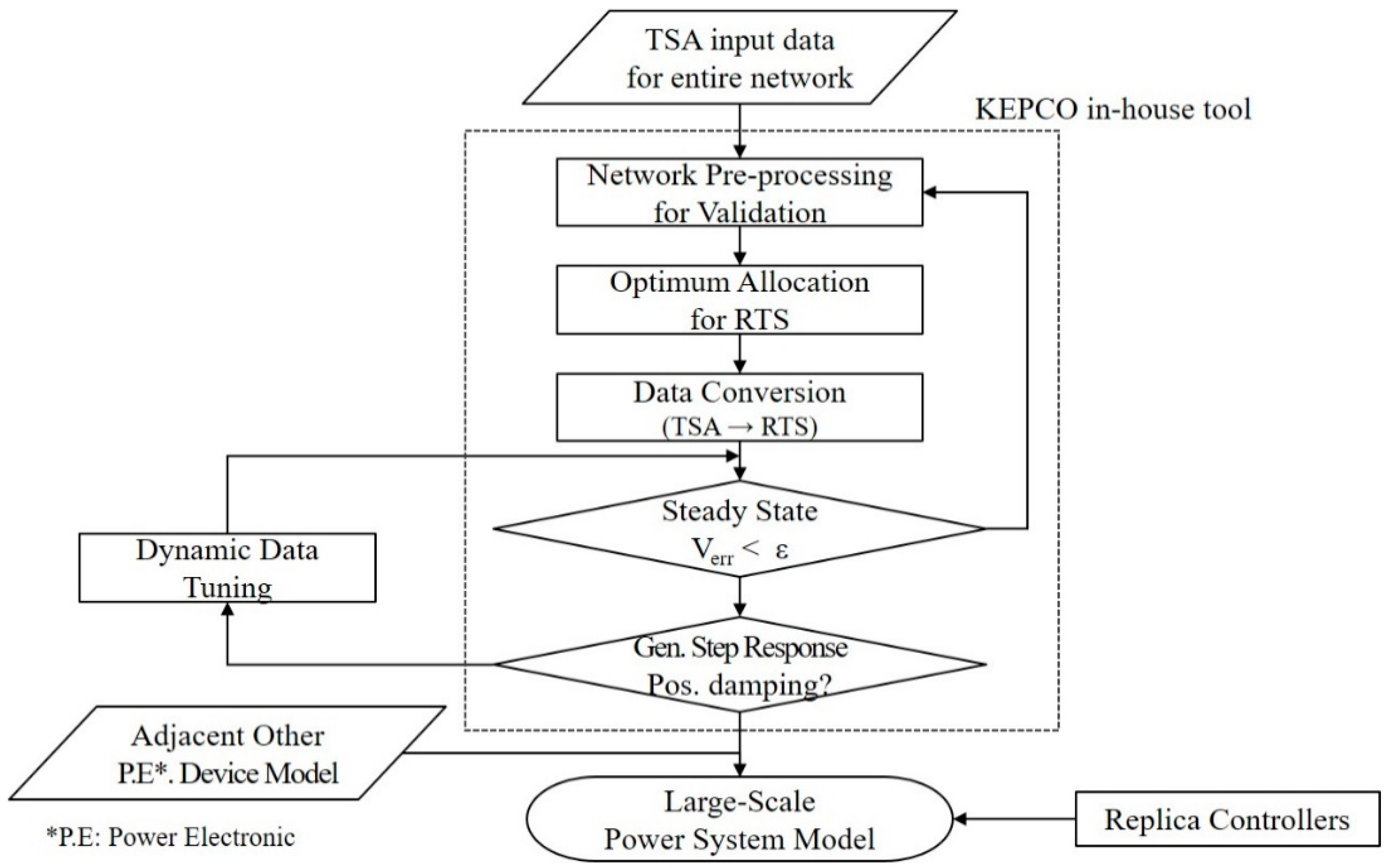
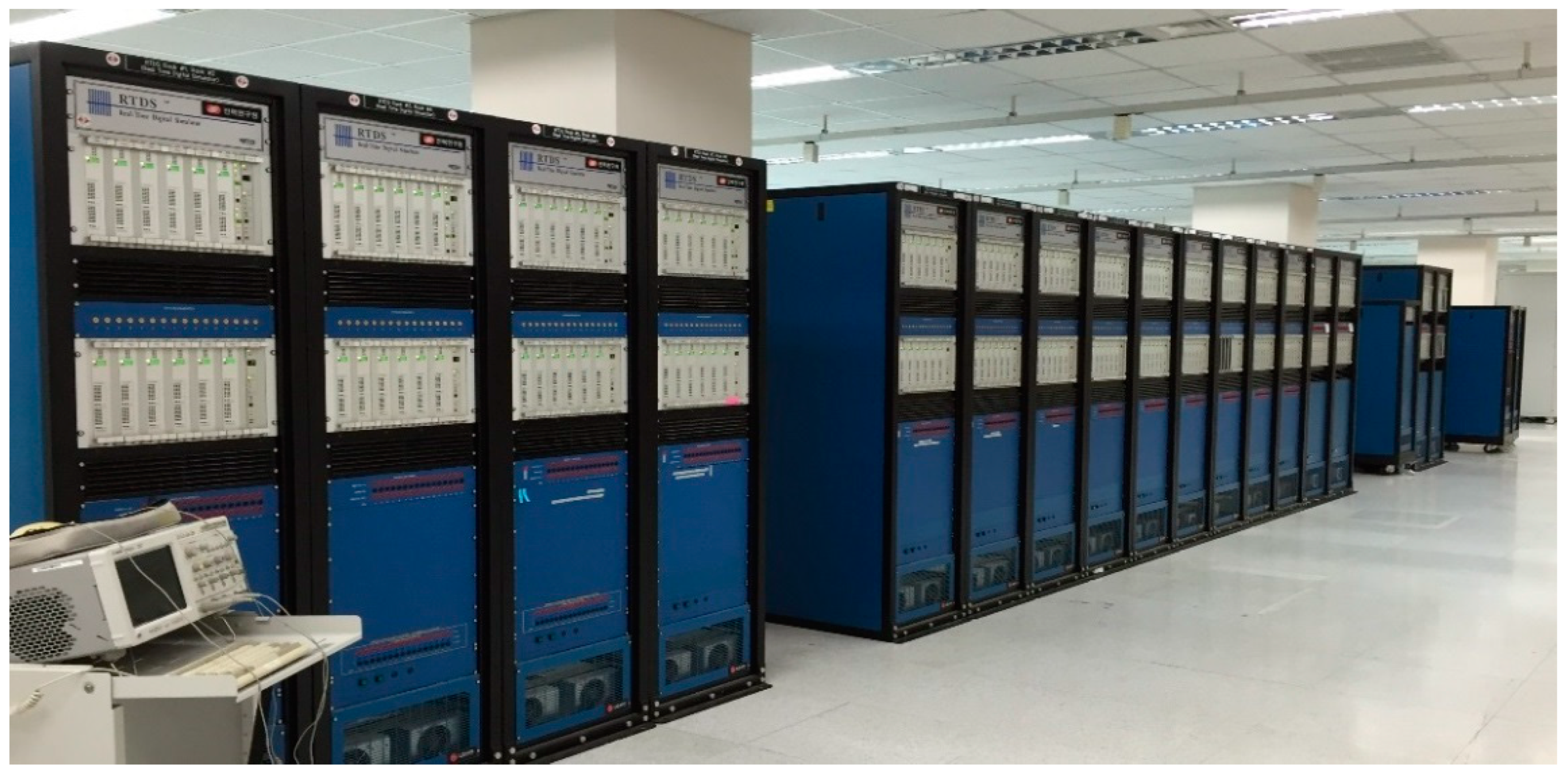
2.2. Large-Scale Real-Time Simulator and Wide Area Network Modeling to Interface with the Replica Controller

KEPCO set up the world’s largest RTDS in 2017 to analyze power systems accurately, including multiple HVDC and FACTS at the EMT level [23]. These include 34 racks of RTDS that are capable of accommodating any kind of future HVDC, FACTS, and transmission systems over 154 kV without equivalent network. This large-scale simulator operation requires significant know-how and operational technology. Therefore, KEPCO has developed and operated a preprocessing in-house tool for stable large-scale power system simulations that now can model, stabilize, and verify a large-scale RTDS case of over 1000 buses in about 2 days [24]. Wide area network modeling with real-time simulator (RTS) is very important, since it is the basis for analysis interfaced with replica controller and for study interaction of adjacent other power electronic devices with network dynamics. This paper suggests the use of data conversion functions in RTS in case of large-scale power system modeling of RTS owing to human error of dealing with huge network data. Most of RTS support data conversion function Transient Stability Analysis (TSA) tool to RTS. Procedure of wide area network modeling with RTS interfaced with replica controller is shown in Figure 2.
It facilitates detailed analysis of the controller to reveal the dynamic characteristic of a wide area network and the interaction between the facilities and power systems at the EMT level. Figure 3 shows the real-time simulation laboratory established in KEPCO.

2.3. Purpose of the Replica Controller

The main purposes of the replica controller are performing the tests that are unavailable in the field, overcoming the limitations of Software In the Loop Simulation (SILS), and performing more precise and accurate analysis [25,26,27,28]. These purposes may vary internationally depending on the configuration of the test environment. KEPCO has defined the following five criteria to set up a replica controller:
  • Dynamic Performance Test (DPT) under large-scale power system: DPT is performed under a sufficiently wide area network to reflect the dynamic characteristics of the power system considering other HVDC and FACTS facilities nearby.
  • Preverification: If the controller needs to be modified, improved, or updated during operation stage, such as adding a new function or in/output signal, the adequacy can be verified and de-risk can be achieved using a replica controller, which cannot be achieved with an actual field controller.
  • Parameter Tuning: The huge changes in power systems, such as an adjacent network topology or the installation of a new power plant, require adjusting the controller parameters. KEPCO conducts verification and parameter tuning periodically for HVDC and FACTS operations for potential severe events, such as 765 kV line fault and Special Protection Scheme (SPS), by planning winter/summer operation strategies biannually.
  • Event Analysis: The replica controller can analyze the root cause of any malfunction or fault due to its detailed internal protection functions. Particularly, KEPCO can simulate not only a single replica controller but also the entire Korean power system, including all HVDC and FACTS manufacturer models with EMT, which facilitates the interaction investigation of the power system and power electronic devices.
  • Operator Training: Training to improve the skill level of the field operators can be conducted. Field operators have few opportunities to deal with actual controllers before project completion. Therefore, the replica controller could be a perfect tool for practical training to gain experience in emergency operation, reaction of communication disruption, alarm analysis, and insertion and block.
For this purpose, KEPCO is planning to set up replica controllers for all HVDC and TCSC in the future, starting with the four TCSC replica controllers installed in 2019.

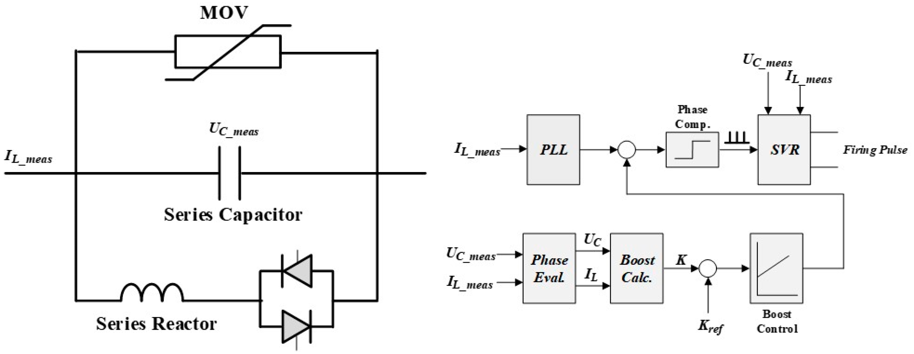
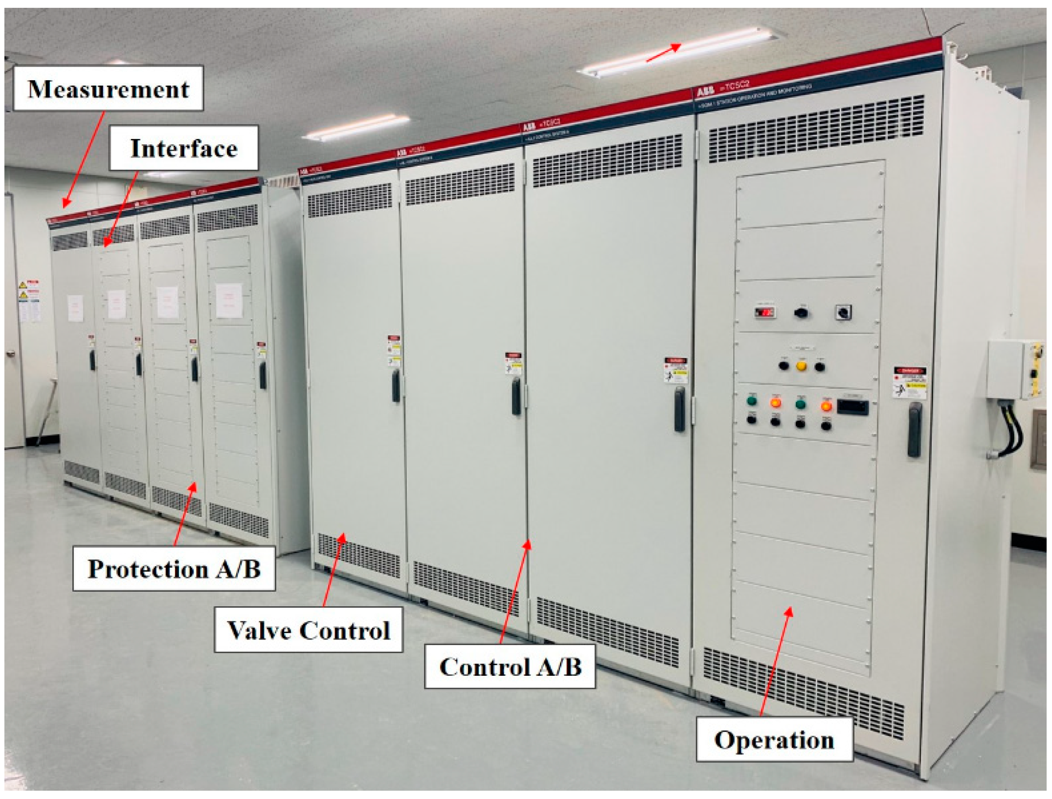
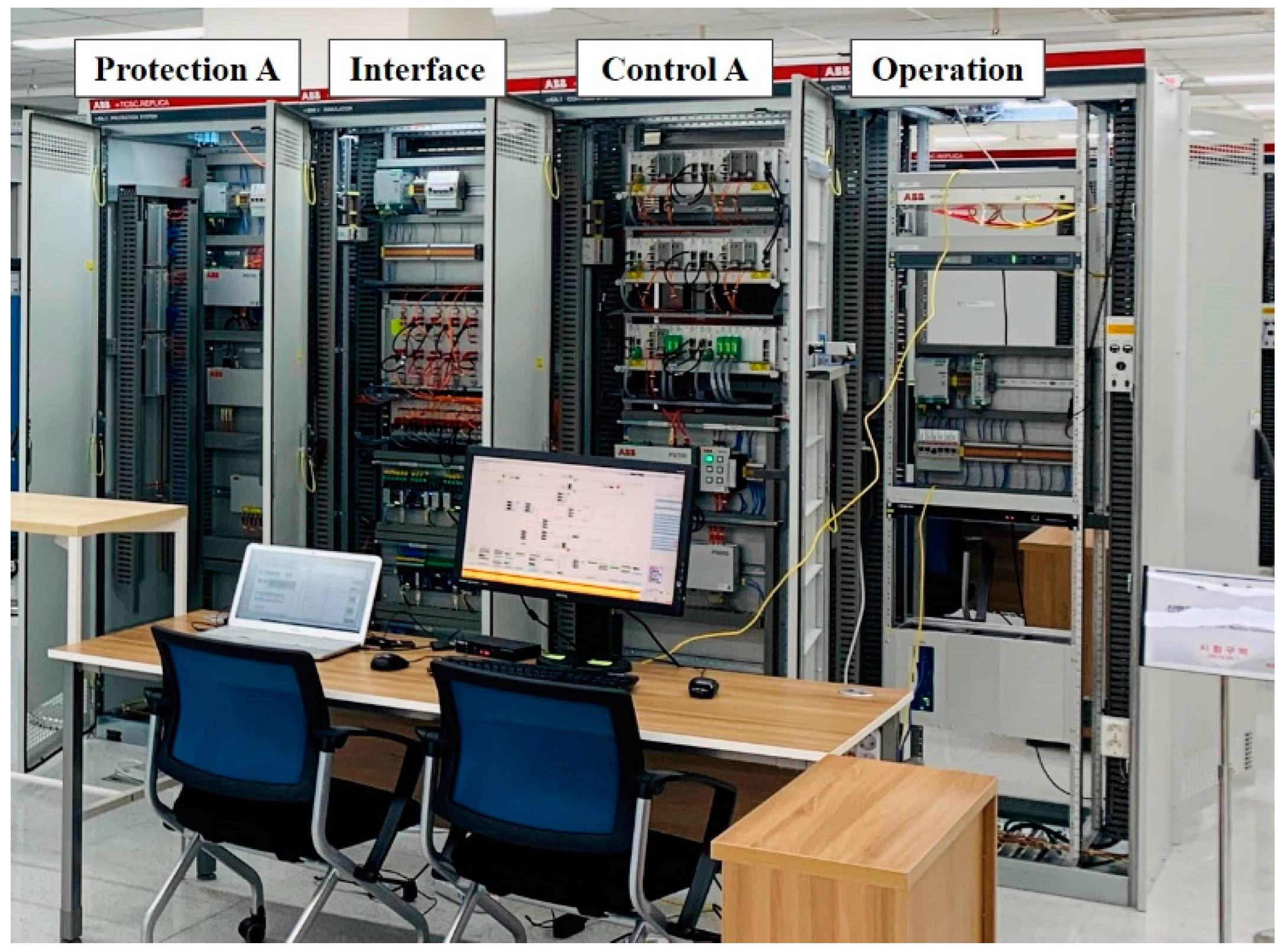
2.4. TCSC Replica Controller

The TCSC is installed to compensate for line impedance by the reactance control (boost factor control). The facility configuration consists of a series capacitor, thyristor valve, reactor, and Metal-Oxide Varistor (MOV). TCSC topology and its conceptual control block are shown in Figure 4 [29].
TCSC topology and the entire network are modeled in a RTS, and the TCSC control and protection systems are implemented on the replica controller. The replica controller receives three analog signals from the real-time simulator: the series capacitor voltage, the thyristor valve current, and the transmission line current. The thyristor firing pulse, the bypass switch, and the boost signal are connected to a digital signal. TCSCs were installed at Shin Youngjoo and Shin Jecheon converter stations. The replica controller is composed of four cubicles: control, protection, operation, and measurement panels. The control, protection, and operation panels have an identical hardware board and embedded software, except for redundancy. Figure 5 and Figure 6 show the actual controller on-site and replica controller in KEPCO laboratory.
The TCSC replica controller offers easy playback and on-site problem analysis capability, because users can adjust various control settings, protection settings, and several control block parameters on the operator system.

3. Practical Cases

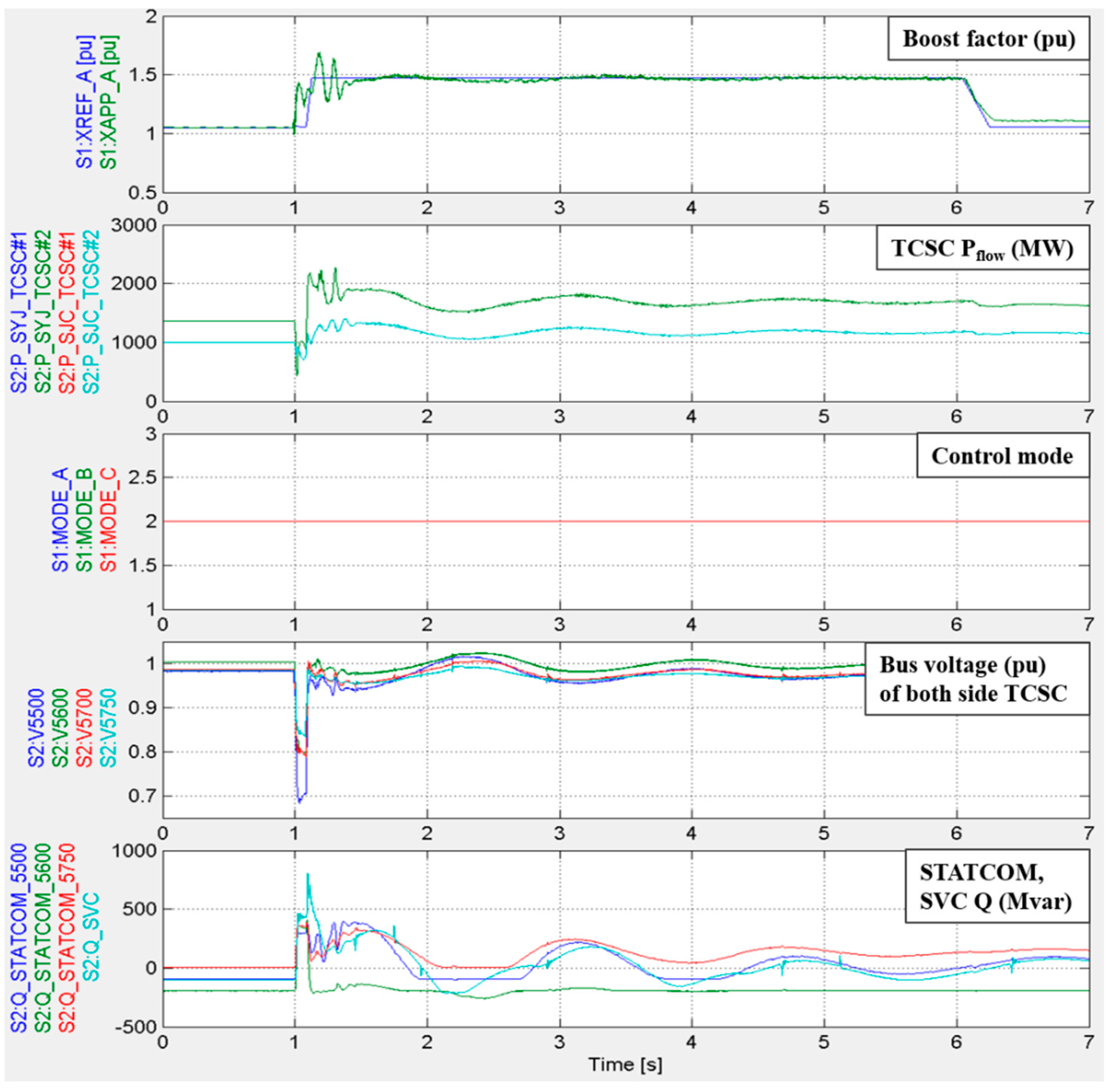
3.1. Dynamic Performance Test (DPT) with Adjacent Multiple FACTS

KEPCO recently established a new DPT procedure between Factory Acceptance Test (FAT) and SAT. As the controller DPT is based on large-scale real-time simulator interfaced with a replica controller, it can overcome the barrier of the previous single unit test in FAT. Furthermore, it is a very realistic test because it contains both system dynamics and multiple HVDC and FACTS control characteristics. There are three STATCOM, one SVC, and 765 kV transmission line nearby TCSC. This case covers the verification results of TCSC’s boost control scheme to improve the transient stability and the control interaction with nearby parallel FACTS in the event of 765 kV failure, as one of the DPT items.
The 2019 winter operation strategy study data were used as the base case. Large-scale system modeling revealed that RTDS takes 28 racks (based on PB5 processor card), 1399 buses, and 358 generators, and the load is 88,734 MW. There are 22 GW bulk generations over 22 generators on eastern coast of Korea, so two nuclear power plants’ trip SPS is applied to maintain transient stability when a 765 kV line fault occurs.
As shown in Figure 7, TCSC maintains a normally capacitive mode (mode: 2) without a bypass or any mode change when a 765 kV line fault occurs, and it follows the boost factor reference appropriately. In addition, both STATCOMs and SVC operate properly to compensate for the low voltage of TCSC and the network near 765 kV transmission line, and to ensure that any control interaction with TCSC does not occur. DPT using the replica controller enables accurate verification of the actual controller’s reliability via realistic testing that reflects the network and control characteristics nearby other power electronic devices on-site.

3.2. Preverification of a Modified Function for an Actual Controller

In the case of TCSC line internal temporary fault, a reinsertion delay of about 1 s was applied in force for stable synchronization of the internal phase lock loop (PLL) controller in the previous control algorithm. After FAT completion, the manufacturer developed a new function called fast reinsertion, and tried to implement it into the actual controller. However, such implementation directly into the actual controller may incur a risk in the absence of any verification using the actual controller. In this practical case, a replica controller is used to pre-verify a new function or a controller improvement to be updated with an on-site actual controller. Figure 8 and Figure 9 show the verification result using a replica controller before and after improvement.
As shown in Figure 8, TCSC still maintains a bypass mode (mode: 4, 5) for about 1.3 (at 3–4.3 s), even after successful line reclosing. However, after the improvement, TCSC is reinserted immediately after successful line reclosing, as shown in Figure 9. In addition to this practical case, several other tests were conducted to validate the reliability of the new function, and then on-site actual controller was successfully updated.

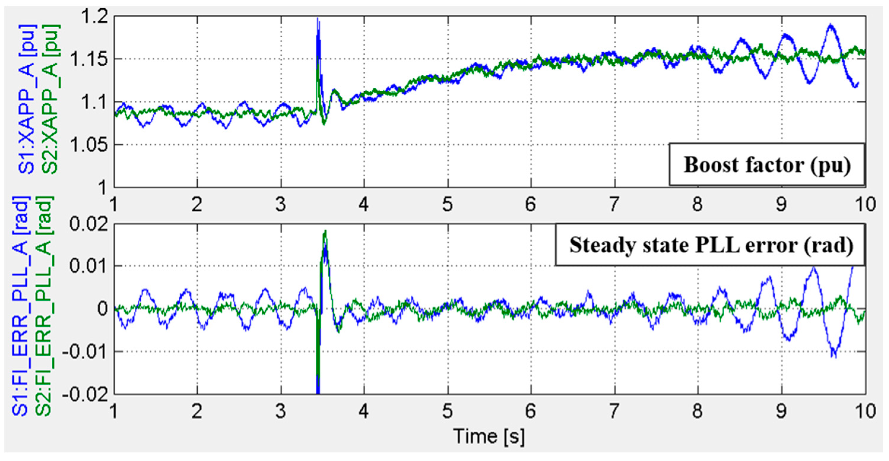
3.3. Parameter Tuning for Control Interaction

During commissioning for Shin Jecheon TCSC#1 and #2, at 1 AM (light load) on November 2019, TCSC#2 was permanently bypassed by a sudden reactance error protection operation shown below Figure 10. Analysis of the fault recorder revealed that TCSC #1 and #2 were in a state of oscillation and hunting each other while reaching to the light-load condition at dawn. As a result of modeling the network condition at that time with a real-time simulator and analyzing it using a replica controller, the error value of the steady-state PLL controller was found to be continuously increasing rather than decreasing.
To mitigate this control interaction, the sensitivity of the replica controller was tuned so that the steady-state PLL proportional gain was changed from 4 to 3 and integration gain increased from 400 to 1000 via the heuristic method. Figure 11 shows the conceptual PLL control block.
The analysis results of the before and after parameter tuning using the replica controller are presented in Figure 12. The oscillation of TCSC was prevented even if #2 had been inserted during TCSC #1 operation, and the steady-state PLL controller error term was also reduced, which verified that the system was under normal control conditions. Several additional tests among the DPT were conducted to verify whether such parameter tuning affects other control performances, and then the on-site controller parameters were finally tuned successfully. Finally, the steady-state PLL gain was suitable for the current power system conditions.
Low-level controller gain tuning does not commonly occur, but it may be needed due to changes in the network condition. Therefore, periodic parameter tuning using the replica controller and the effect on the system should be verified in advance. In June 2020, two 1.4 GW nuclear power plants will be connected to the power system nearby the TCSC sending end, and optimal parameter tuning adapted to the changed network condition will be undertaken again.

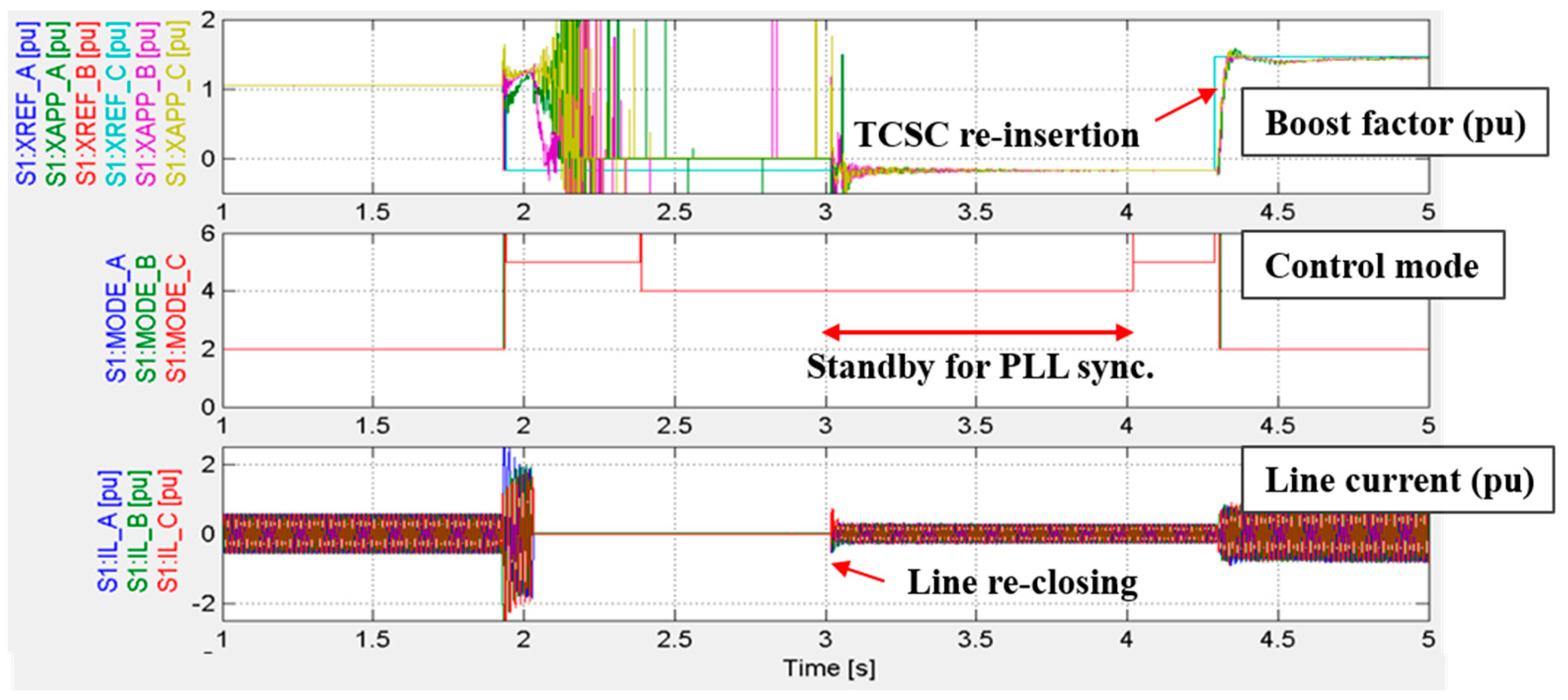
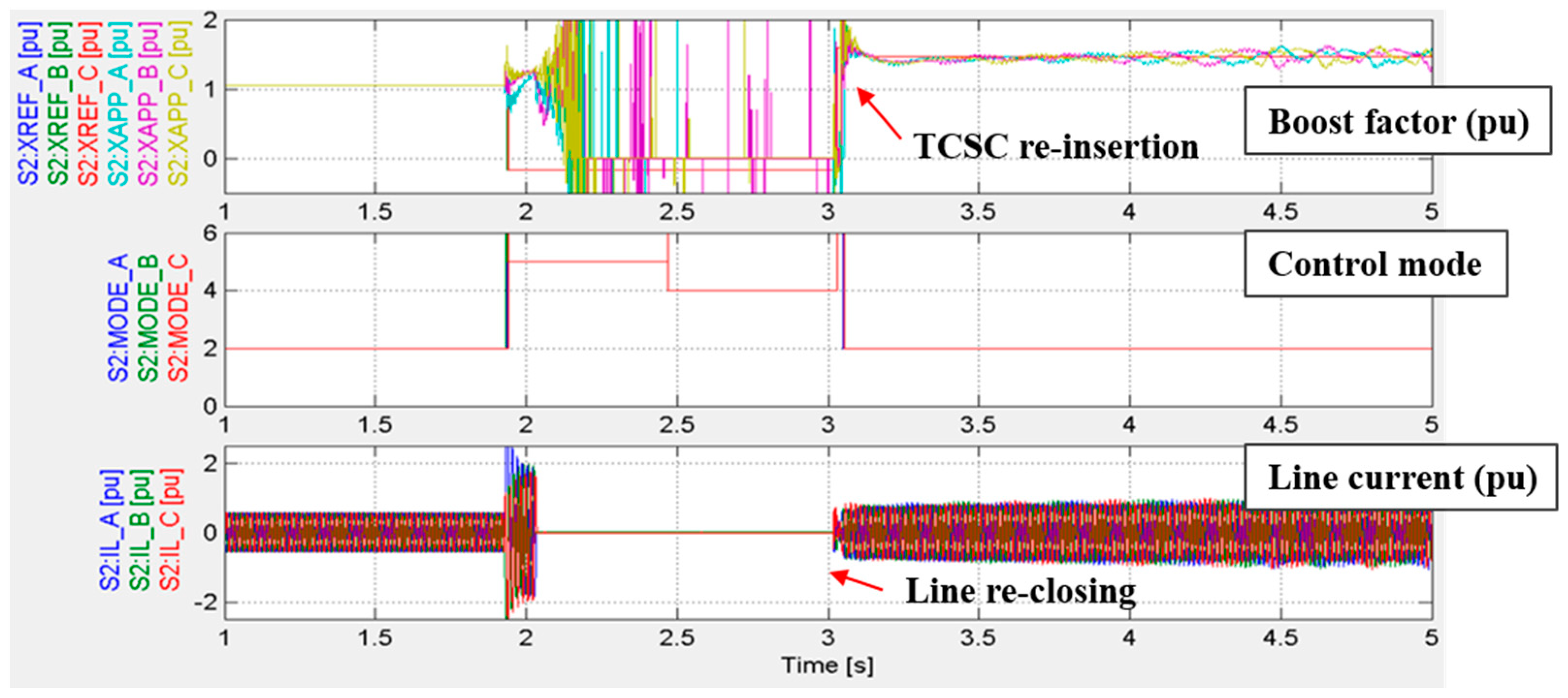
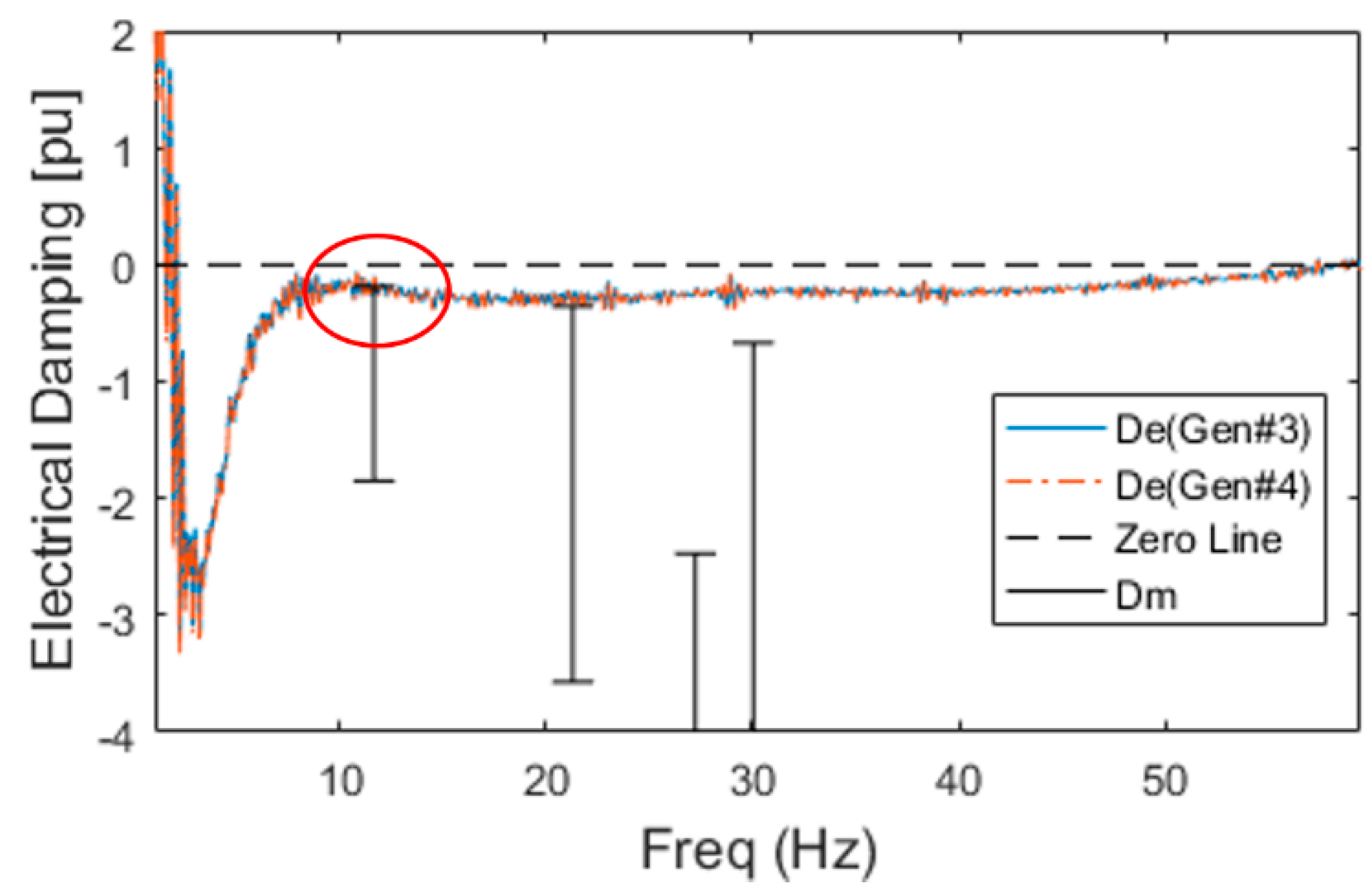
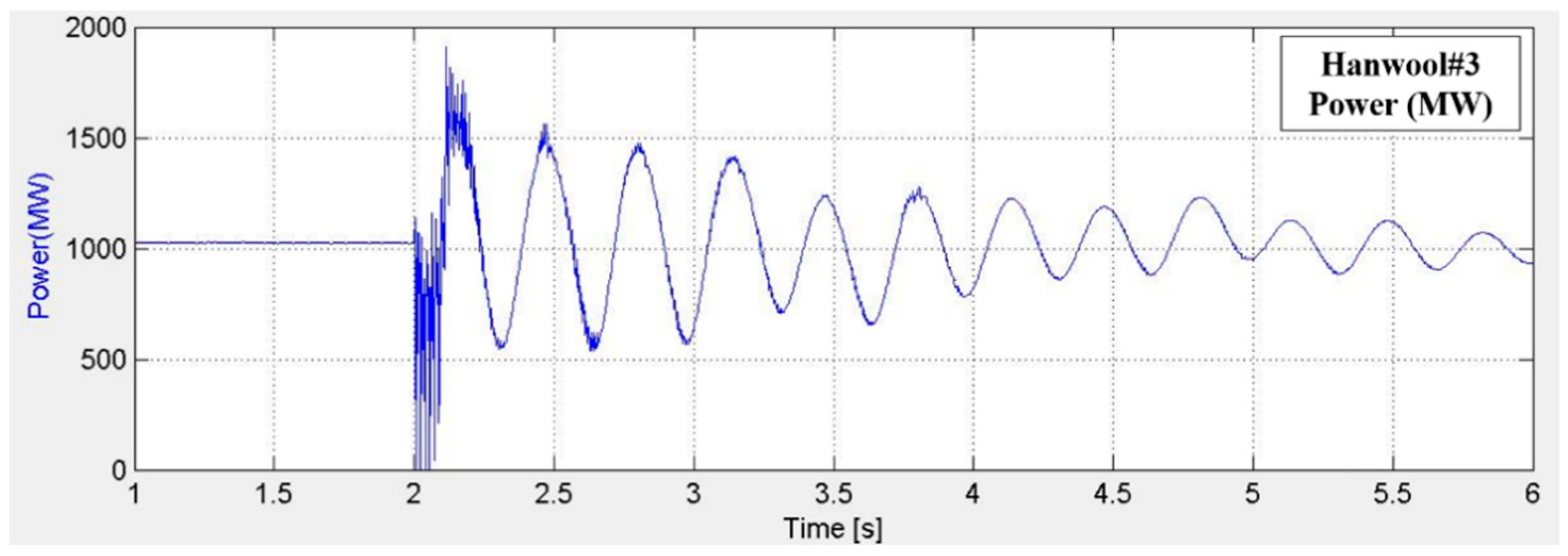
3.4. Subsynchronous Torsional Interaction (SSTI) Validation under a Large-Scale Power System

During the operation stage, the actual SSTI analysis needs to consider the additional damping provided by the adjacent generator, HVDC, and FACTS. Therefore, KEPCO modeled the entire Korean power system without the equivalent network, interfaced with the TCSC replica controller, and applied damping analysis to investigate the possibility of SSTI occurrence. In the event of SSTI, the target generator is modeled with a multi-mass model and time domain simulation for the entire Korean power system is carried out to identify the problem accurately. In this practical case, three STATCOMs and one SVC are considered in addition to the target generator of SSTI analysis. Figure 13 and Figure 14 show the single line diagram and damping analysis result, respectively, for Hanwool nuclear power plant (NP) #2 and TCSC.
The Hanwool #3 and #4, which are the target generators for the analysis, are radially connected to TCSC at the N-6 contingency, which has a little negative damping at the generator’s minimum output around 12.3 Hz mode frequency. We finally identified that it had positive damping through the time domain simulation for SSTI possibility, as shown in Figure 15.

4. Conclusions

The importance of replica controllers has recently increased owing to the expansion of HVDC and FACTS facilities. Such replica controllers have been installed mainly in China, Canada, and Europe. In this paper, we described the first replica controller set up in Korea, and presented the more realistic test, analysis, and operation as applicable and necessary under the actual network conditions. In addition, we represented its usefulness for application to the following four practical cases: DPT under a large-scale power system, preverification parameter tuning, event analysis, and SSTI occurrence verification. The replica controllers that demonstrated the usefulness of their on-site application in all four cases could not be performed on-site. The analysis results of these practical experiences offer great value by contributing to the stable future operation of multiple HVDC and FACTS. In particular, since different types and manufacturers of equipment are operated together in the real world, we will prepare and study for interoperability and interaction using multiple replica controllers in the future under an upcoming complicated power system.
Following on from the first TCSC replica controller, KEPCO will continue to setup more HVDC and FACTS replica controllers, and further research and development are being conducted related to its operation and analysis technology for mutual control interaction issues from multivendor replica controllers to adjacent facilities. The integration and comprehensive analysis of multiple replica controllers in the future will require standardization of the replica controllers’ technical specifications to optimize the flexibility and interoperability from a perspective of electric utility.

Author Contributions

Conceptualization, J.S. (Jiyoung Song) and G.J.; methodology, J.S. (Jiyoung Song) and J.L.; software, J.S. (Jeonghoon Shin). and S.O.; validation, G.L., J.S. (Jeonghoon Shin), and G.J.; investigation, J.S. (Jiyoung Song) and S.O.; resources, S.O. and J.L.; data curation, S.O.; writing—original draft preparation, J.S. (Jiyoung Song); writing—review and editing, J.S. (Jiyoung Song) and G.J.; supervision, G.J.; All authors have read and agreed the published version of the manuscript.

Funding

This research received no external funding.

Conflicts of Interest

The authors declare no conflict of interest.

References

  1. Barens, M.; Van Hertem, D.; Teeuwsen, S.P.; Callavik, M. HVDC Systems in smart grids. In Proceedings of the IEEE, New York, NY, USA, 11 November 2017; pp. 2082–2098. [Google Scholar] [CrossRef]
  2. Henderson, M.; Bertagnolli, D.; Ramey, D. Planning HVDC and FACTS in New England. In Proceedings of the 2009 IEEE/PES Power Systems Conference and Exposition, Seattle, DC, USA, 24 April 2009; pp. 1–3. [Google Scholar] [CrossRef]
  3. Sun, J.; Li, M.; Zhang, Z.; Xu, T.; He, J.; Wang, H.; Li, H. Renewable energy transmission by HVDC across the continent: System challenges and opportunities. CSEE J. Power Energy Syst. 2017, 3, 353–364. [Google Scholar] [CrossRef]
  4. Collados-Rodríguez, C.; Prieto-Araujo, E.; Cheah-Mañé, M.; San José, R.F.; Bellmunt, O.G.; Sanz, S.; Longás, C.; Cordón, A.; Coronado, A. Interaction analysis in islanded power systems with HVDC interconnections. In Proceedings of the 3rd International Hybrid Power Systems Workshop, Tenerife, Spain, 8–9 May 2018; pp. 1–5. [Google Scholar]
  5. Saad, H.; Dennetière, S.; Clerc, B. Interactions investigations between power electronics devices embedded in HVAC network. In Proceedings of the 13th IET International Conference on AC and DC Power Transmission (ACDC 2017), Manchester, UK, 14–16 February 2017; pp. 1–7. [Google Scholar] [CrossRef]
  6. Shen, L.; Barnes, M.; Milanovic, J.V.; Bell, K.R.W.; Belivanis, M. Potential interactions between VSC HVDC and STATCOM. In Proceedings of the 2014 Power Systems Computation Conference, Wroclaw, Poland, 18–22 August 2014; pp. 1–7. [Google Scholar] [CrossRef]
  7. Guillaud, X.; Faruque, M.O.; Teninge, A.; Hariri, A.H.; Vanfretti, L.; Paolone, M.; Dinavahi, V.; Mitra, P.; Lauss, G.; Dufour, C.; et al. Applications of Real-Time simulation technologies in power and energy systems. IEEE Power Energy Technol. Syst. J. 2015, 2, 103–115. [Google Scholar] [CrossRef] [Green Version]
  8. Iyoda, I.; Belanger, J. History of power system simulators to analyze and test of power electronics equipment. In Proceedings of the 2017 IEEE HISTory of ELectrotechnolgy CONference (HISTELCON), Kobe, Japan, 7–8 August 2017; pp. 117–120. [Google Scholar] [CrossRef]
  9. Omar Faruque, M.D.; Strasser, T.; Lauss, G.; Jalili-Marandi, V.; Forsyth, P.; Dufour, C.; Dinavahi, V.; Monti, A.; Kotsampopoulos, P.; Martinez, J.A.; et al. Real-Time simulation technologies for power systems design, testing and analysis. IEEE Power Energy Technol. Syst. J. 2015, 2, 63–73. [Google Scholar] [CrossRef]
  10. Guo, Y.; Zhang, J.; Hu, Y.; Han, W.; Ou, K.; Jackson, G.; Zhang, Y. Analysis on the effects of STATCOM on CSG based on RTDS. In Proceedings of the IEEE PES ISGT Europe 2013, Lyngby, Denmark, 6 January 2014; pp. 1–5. [Google Scholar] [CrossRef]
  11. RTDS Technologies Inc. Large-scale-simulators. Available online: https://legacy.rtds.com/wp-content/uploads/2015/12/Large-scale-simulators.pdf (accessed on 15 January 2020).
  12. Wang, Y.; Syed, M.H.; Guillo-Sansano, E.; Xu, Y.; Burt, G.M. Inverter-Based Voltage Control of Distribution Networks: A Three-Level Coordinated Method and Power Hardware-in-the-Loop Validation. IEEE Trans. Sustain. Energy 2019. [Google Scholar] [CrossRef] [Green Version]
  13. Song, J.; Nam, S.; Lee, J.; Shin, J.; Kim, T.K. Construction of test bed with RTDS for verifying coordination algorithm for loop distribution system. J. Int. Counc. Electr. Eng. 2010, 2, 467–472. [Google Scholar] [CrossRef] [Green Version]
  14. Saran, A.; Kankanala, P.; Srivastava, A.K.; Schulz, N.N. Designing and testing protective overcurrent relay using real time digital simulation. In Proceedings of the 2008 International Simulation Multi-conference & 2008 Summer Simulation Multiconference, Edinburgh, Scotland, 16–19 June 200.
  15. Wang, Z.; Kent, K.; Mantay, C.; Zhou, C.; Wang, P.; Fang, C.; Dhaliwal, N.; Menzies, D. HVDC control replica development for Nelson Reiver Bipole 1&2. In Proceedings of the CIGRE Winnipeg 2017 Colloquium, Winnipeg, MB, Canada, 30 September–6 October 2017; pp. 329–338. [Google Scholar]
  16. Cowan, I.L.; Marshall, S.C.M. Installation and interfacing HVDC control replicas at the national HVDC centre. In Proceedings of the 15th IET International Conference on AC and DC Power Transmission (ACDC 2019), Coventry, UK, 18 April 2019; pp. 1–6. [Google Scholar] [CrossRef]
  17. Vernay, Y.; D’Aubigny, A.D.; Benalla, Z.; Dennetière, S. New HVDC LCC replica platform to improve the study and maintenance of the IFA2000 link (Conf, IPST). In Proceedings of the International Conference on Power Systems Transients 2017 (IPST 2017), Seoul, Korea, 26–29 June 2017. [Google Scholar]
  18. Beijing DC Consultants (BDCC), Zhejiang EPRI and RTDS Technologies Inc. Application of Replica HVDC Controller with Real Time Digital Simulation-Experiences in SGCC. In Proceedings of the 2016 Cigre Session, Paris, France, 22–26 August 2016. [Google Scholar]
  19. Best Paths. Final Recommendations for Interoperability of Multivendor HVDC. Available online: http://www.bestpaths-project.eu/contents/publications/d93--final-demo2-recommendations--vfinal.pdf (accessed on 12 December 2019).
  20. Kim, S.; Kim, H.; Lee, H.; Lee, J.; Lee, B.J.; Jang, G.; Lan, X.; Kim, T.; Jeon, D.; Kim, Y.; et al. Expanding power systems in the Republic of Korea feasibility studies and future challenges. IEEE Power Energy Mag. 2019, 17, 61–72. [Google Scholar] [CrossRef]
  21. Moon, B.; Ko, B.; Choi, J. The study on the efficient HVDC capacity considering extremely low probability of 765 kV double circuit. J. Electr. Eng. Technol. 2017, 12, 1046–1052. [Google Scholar] [CrossRef]
  22. Kim, S.H.; Oh, H.; Moon, B. A Study on the application of HVDC FACTS System in the Northeast Power System of Korea. J. Int. Counc. Electr. Eng. 2011, 1, 437–440. [Google Scholar] [CrossRef] [Green Version]
  23. Park, I.K.; Lee, J.; Song, J.; Kim, Y.; Kim, T. Large-scale ACDC EMT level system simulations by a real time digital simulator (RTDS) in KEPRI-KEPCO. J. Electr. Power Energy 2017, 3, 17–21. [Google Scholar] [CrossRef]
  24. Hur, K.; Lee, J.; Song, J.; Ko, B.; Shin, J. Advanced Real Time Power System Simulator for Korea Electric Power Systems: Challenges and Opportunities. IEEE PES. 2018. Available online: http://site.ieee.org/pes-itst/files/2018/08/2018-Panel-1.pdf (accessed on 23 January 2019).
  25. CIGRE Working Group B4.38. Modeling and Simulation Studies to Be Performed during the Lifecycle of HVDC Systems; CIGRE Technical Brochure: Paris, France, 2013. [Google Scholar]
  26. Kotsampopoulos, P.; Georgilakis, P.; Lagos, D.T.; Kleftakis, V.; Hatziargyriou, N. FACTS providing grid services: Applications and testing. Energies 2019, 12, 2554. [Google Scholar] [CrossRef] [Green Version]
  27. Ou, K.; Li, H. Function and dynamic performance test of the updated Tian-Guang HVDC control and protection systems. Adv. Mater. Res. 2012, 516, 1527–1530. [Google Scholar] [CrossRef]
  28. Guay, F.; Chiasson, P.; Verville, N.; Tremblay, S.; Askvid, P. New hydro Quebec real time Simulation interface HVDC commissioning studies. In Proceedings of the International Conference on Power Systems Transients 2017 (IPST 2017), Seoul, Korea, 25–29 June 2017. [Google Scholar]
  29. Angquist, L. Synchronous Voltage Reversal Control of Thyristor Controlled Series Capacitor; TRITA-ETS; Royal Institute of Technology in Stockholm: Stockholm, Sweden, July 2002; ISSN 1650-674X. [Google Scholar]
Figure 1. HVDC, FACTS in the Korean power system.
Energies 13 03343 g001
Figure 2. Flow chart of wide area network modeling procedure for real-time simulator (RTS) interfaced with replica controller.
Energies 13 03343 g002
Figure 3. Real-time Digital Simulator in the Korea Electric Power Corporation (KEPCO) Research Institute.
Energies 13 03343 g003
Figure 4. Thyristor Controlled Series Compensator (TCSC) topology and conceptual control block.
Energies 13 03343 g004
Figure 5. TCSC actual controller on-site.
Energies 13 03343 g005
Figure 6. TCSC replica controller in Korea Electric Power Corporation (KEPCO) lab.
Energies 13 03343 g006
Figure 7. TCSC and other FACTS output.
Energies 13 03343 g007
Figure 8. TCSC boost factor (before improvement).
Energies 13 03343 g008
Figure 9. TCSC boost factor (after improvement).
Energies 13 03343 g009
Figure 10. TCSC bypassed on site.
Energies 13 03343 g010
Figure 11. Phase lock loop (PLL) conceptual PI control block.
Energies 13 03343 g011
Figure 12. Comparison between before/after parameter tuning.
Energies 13 03343 g012
Figure 13. Single line diagram near TCSC.
Energies 13 03343 g013
Figure 14. Damping analysis result.
Energies 13 03343 g014
Figure 15. Time domain simulation result in light load of generator.
Energies 13 03343 g015

