1. Introduction
Rotary vane pumps are suitable for multiple applications due to their advantages of compactness, lightweight, low cost and low bearing forces [
1,
2,
3,
4,
5]. One main application for rotary vane pumps is the usage as oil pump for automatic transmissions [
6,
7]. In this case, the advantages of rotary vane pumps overpower the advantages of other pumping principles.
In recent years, the acoustic characteristic of systems, especially in the automotive field, has become increasingly important. This is due to lower noise emissions of connected systems and higher customer demands regarding the driving comfort. In hydraulic circuits, e.g., automatic transmissions for cars, the pump is often identified as a major source of noise [
3,
8]. Therefore, a better understanding of the characteristic flow phenomena, which are causing the noise in the pump, is mandatory.
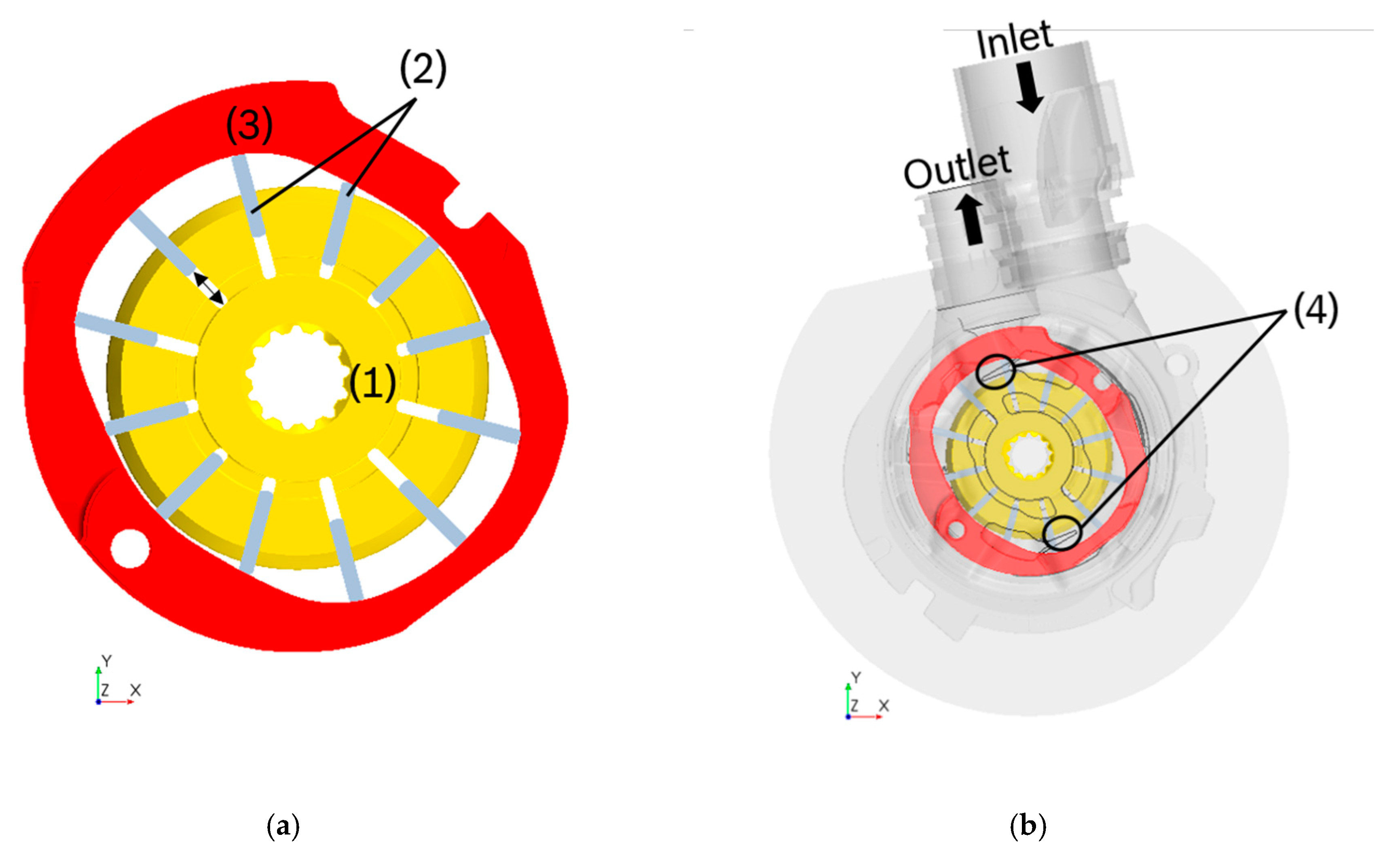
A rotary vane pump consists of a stator part along with the cam ring, a rotor and vanes, which have a degree of freedom in radial direction (
Figure 1a). This components are embedded in the housing of the pump which connects the pump to the hydraulic system (
Figure 1b). When the rotor is rotating, the vanes (2) move in and out of the rotor (1), depending on the shape of the cam ring curve (3). The space between rotor (1) and vanes (2) is called back vane volume and is connected to the delivery port. This connection increases the pressure in the back vane volume and ensures that the vanes slide along the cam ring surface (3). The space between the cam ring (3), the rotor (1) and two vanes (2) forms a displacement chamber of the pump. These displacement chambers are pressure sealed, so that a different pressure level can prevail in adjacent displacement chambers. The volume of a displacement chamber changes during the rotation depending on the angular position of the vanes. At the suction ports, the volume increases, which leads to suction and thus draws the liquid into the chamber. At the delivery ports, the displacement chamber volume decreases and subsequently, the fluid is pushed out. One displacement chamber is connected either to the suction, or to the delivery port. This means that there is a permanent spatial separation of delivery and suction port [
1]. If a displacement chamber with low pressure connects to the delivery port, this leads to a sudden pressure surge in the displacement chamber. Similar to the Joukowsky shock, this pressure surge is caused by a sudden change in the flow direction of the fluid motion [
9]. Since there is a high pressure gradient during the transition of a displacement chamber from the suction to the delivery port, leakages can arise in the radial gaps (lubrication film between vane and cam ring) and the axial gaps at the top and bottom of the rotor and vanes. Overall, this working principle causes flow and pressure pulsations, which are decisive for the pump’s noise radiation [
3,
10]. The fluidborne noise, caused by the pumping action, excites other structural elements, resulting in vibrations and a radiation of airborne noise [
11]. The pressure surges, which arise during the transition from the suction to the delivery port, can be reduced by lower pressure gradients between the displacement chamber with low pressure, which connects to the delivery port and the pressure at the delivery port itself. This can be realized by two different known approaches.
One approach is to start the reduction in the chamber volume and compression of the oil in advance of the connection to the delivery port (precompression). Therefore, the pressure of the displacement chamber is already at a higher pressure level when the displacement chamber connects to the delivery port. This leads to smaller pressure gradients and pressure surges. Another approach to reduce this pressure surge is adding a small connection between delivery port and the next connecting displacement chamber to enhance the pressure in this chamber, before the chamber connects to the delivery port. This connection is called groove (4) and can be seen in
Figure 1b. It is usually implemented at the delivery port in the pump housing.
Due to the high pressure gradients and the low compressibility of the oil, small changes in the groove shape and position in conjunction with the precompression have a big impact on the resulting pressure surge. Presently, the final shape and size of the grooves is evaluated by experiments.
The internal pressure distribution in a displacement chamber is affected by different variables such as the pump geometry, the delivery pressure and the pump rotational speed [
12]. To get a deeper insight into these phenomena, it is essential to observe flow phenomena in the pump and in a displacement chamber itself. Measurements inside the pump are very hard to obtain as well as time consuming and expensive [
13]. In the simulation flow phenomena can be observed in detail, which cannot be obtained by measurements. As a consequence, a numerical approach is chosen for the investigation of flow phenomena in the pump.
In this work the commercial software STAR-CCM+ is used for the computational fluid dynamics (CFD) simulations. A summary of the applied modelling approaches for a CFD model of a rotary vane pump is presented. This model is used for the investigation of the internal pressure of a displacement chamber during the pump operation. Simulation parameters are adjusted to achieve a better convergence and critical parameters that influence the solution are pointed out. These simulation results are compared to measurements of the internal displacement chamber pressure and the impact of different operating conditions such as the rotational speed and the delivery pressure on the internal displacement pressure curve is analyzed. Specific flow phenomena visible in the pressure curve of a displacement chamber are related to flow phenomena of other displacement chambers and to the angular position of the vanes in the pump geometry by means of the simulation.
2. Measurements
To obtain validation data for the simulations, measurements are performed. Measurements of the internal displacement chamber pressure are appropriate to validate the simulations, since the effects of connected hydraulic components such as reflections are less significant in the pump itself. Effects such as the pressure surge due to the compression and the connection to the delivery port are only directly observable in this kind of measurement.
In order to perform these measurements, a test bench similar to the simulation setup of Suzuki has been built up [
14]. A transducer placed in one of the rotating displacement chambers is recording the pressure during the pump operation. The measured data are transmitted from the rotating rotor via a slip ring transmitter. The cabling from the sensor to the slip ring transmitter is through a hollow drilled shaft. A schematic description of the setup can be seen in
Figure 2. The measurements conducted with this setup were able to monitor the internal displacement chamber pressure up to a rotational speed of 3000 rpm at a delivery pressure of
20 bar.
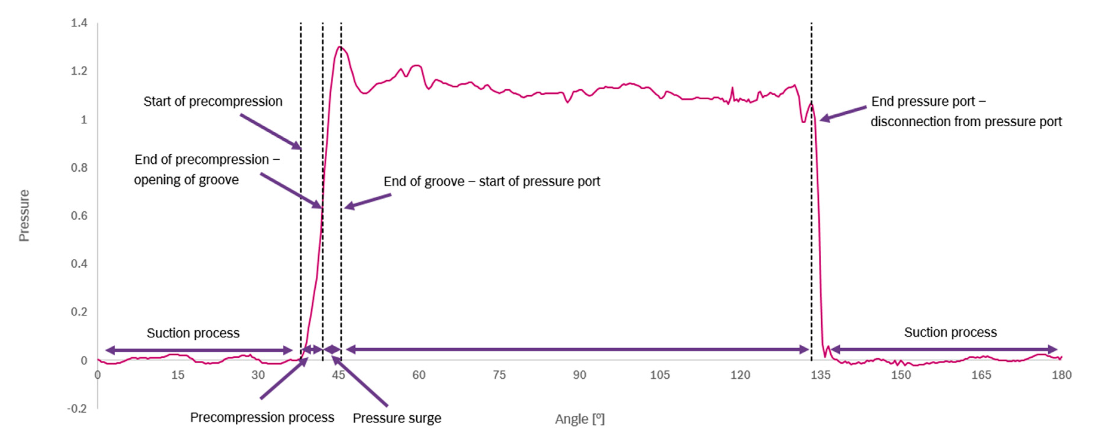
A characteristic pressure curve of the pressure in the displacement chamber during the pump operation is displayed in
Figure 3. The y-axis of the graph shows the normalized pressure (by 20 bar), to focus on characteristic flow phenomena. At the suction port (at an angle 0° to 38°), the absolute pressure is about one bar, depending on the rotational speed of the pump. If the rotational speed increases, the static pressure at the suction port drops, leading to an enhanced cavitation susceptibility. When the displacement chamber disconnects from the suction port and is still disconnected from the delivery port, the precompression (a small reduction in the displacement chamber volume) sets in. Subsequently, the pressure of the fluid in the chamber starts to rise, because the fluid is trapped in this displacement chamber and outflow is only possible through axial and radial gaps (leakage). At an angle of 42°, the preceding vane of the displacement chamber passes the groove and a direct connection to the delivery port opens. Due to the pressure gradient between the lower pressure of the displacement chamber and the higher pressure at the delivery port, additional oil is flowing into the chamber through the groove. This leads to a further pressure rise in the displacement chamber. The inertia and viscosity of the oil can cause a pressure surge (here at an angle of about 45.5°) if the coordination of precompression and groove size is not optimized for the operating point [
15]. This means that the size of the groove depends on the operating condition of the pump, because at lower rotation rates more time is available for the fluid to flow into the chamber leading to higher pressure rises in advance of the connection. With higher rotation rates it is vice versa. The volumetric flow rate through the groove mainly depends on the groove size and the pressure gradient and can assumed to be equal for different rotational speeds.
Subsequently, the displacement chamber is completely connected to the delivery port. In this phase, the chamber volume reduces further on and the oil is pushed out of the chamber. Here, the pressure stays nearly at the same level (at angle 50° to 130°). Only small fluctuations arise on this high pressure plateau caused by reflections and interaction with other displacement chambers. When the displacement chamber disconnects from the delivery port, the pressure drops again to the suction port pressure level. At some operating points, an additional pressure surge occurs while the chamber disconnects from the delivery port (at an angle of 133°). This is caused by the inertia of the fluid, which is not able to exit from the disconnected displacement chamber (see
Figure 3). Measurements show that these effects are even more distinct at higher rotational speeds or at lower temperatures when the viscosity of the fluid is higher.
Figure 3 shows the pressure in a displacement chamber during one transition from suction to pressure port and one transition from pressure to suction port. Since the analyzed pump is a double-stroke fixed type vane pump, the displacement chamber passes two suction and two delivery ports per rotation. In this type of pump, the suction and delivery ports are located diametrically opposite to each other. Therefore, the opposite delivery ports balance the forces acting against the rotor and reduce the pump shaft oscillations and overall vibrations [
16]. This pump type is called a balanced pump.
3. Simulation Setup
To build up a CFD simulation of a rotary vane pump, the commercial software STAR-CCM+ is used. Due to the pump’s working principle, there are rotating and stationary parts in the pump. Since the vanes are sliding in and out of the rotor, the shape of the displacement chambers changes in radial and angular direction. To model the rotating displacement chambers, a motion function for the radial movement of the vanes in form of coordinates or velocities along with a mesh motion approach is needed. In STAR-CCM+, different possibilities to apply a motion to meshes are available. It is either possible to calculate a motion directly using the pressure force acting on a part (dynamic fluid body interaction), or to use a prescribed motion.
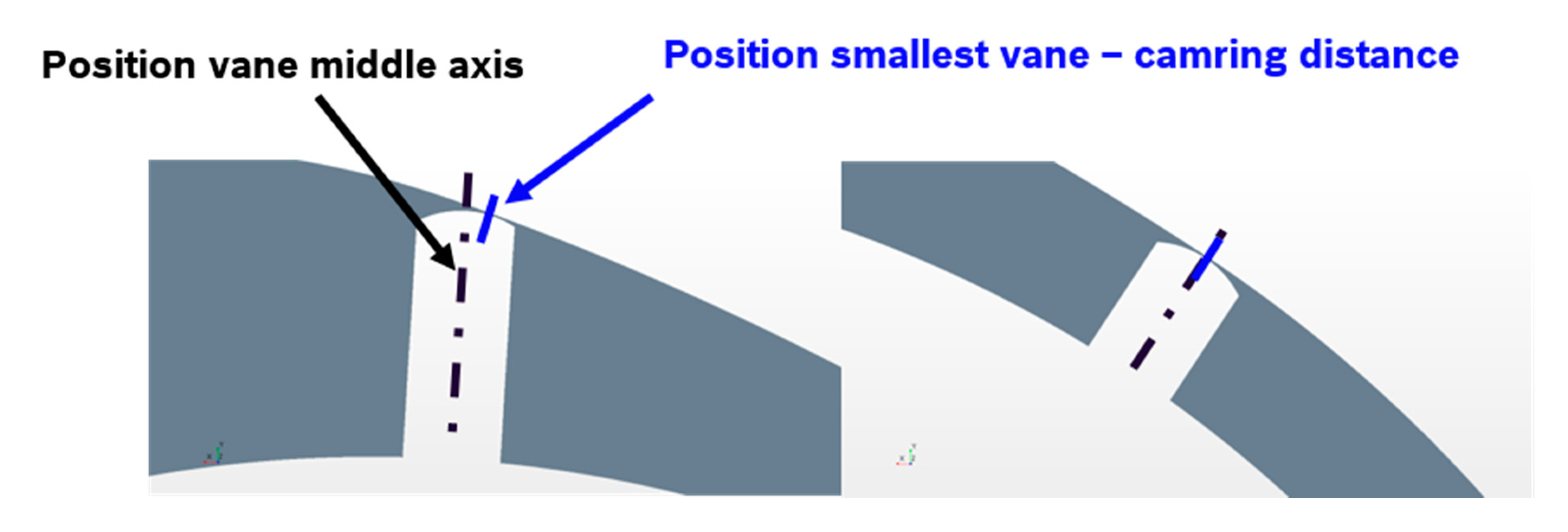
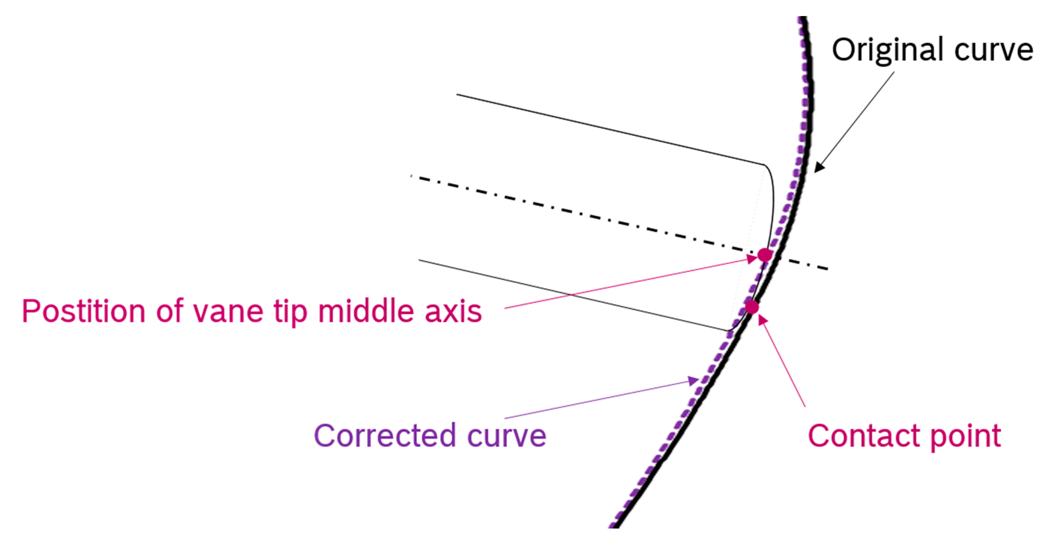
In the first step, an approach with a prescribed motion is chosen, because the modelling of the dynamic fluid body interaction is more computational demanding and it is hard to validate the correctness of the resulting motion. The prescribed motion uses a velocity function to capture the trajectory of the vanes. Due to the different radii of vane tip and cam ring, the contact point moves from the vane middle axis depending on the angular position (see
Figure 4).
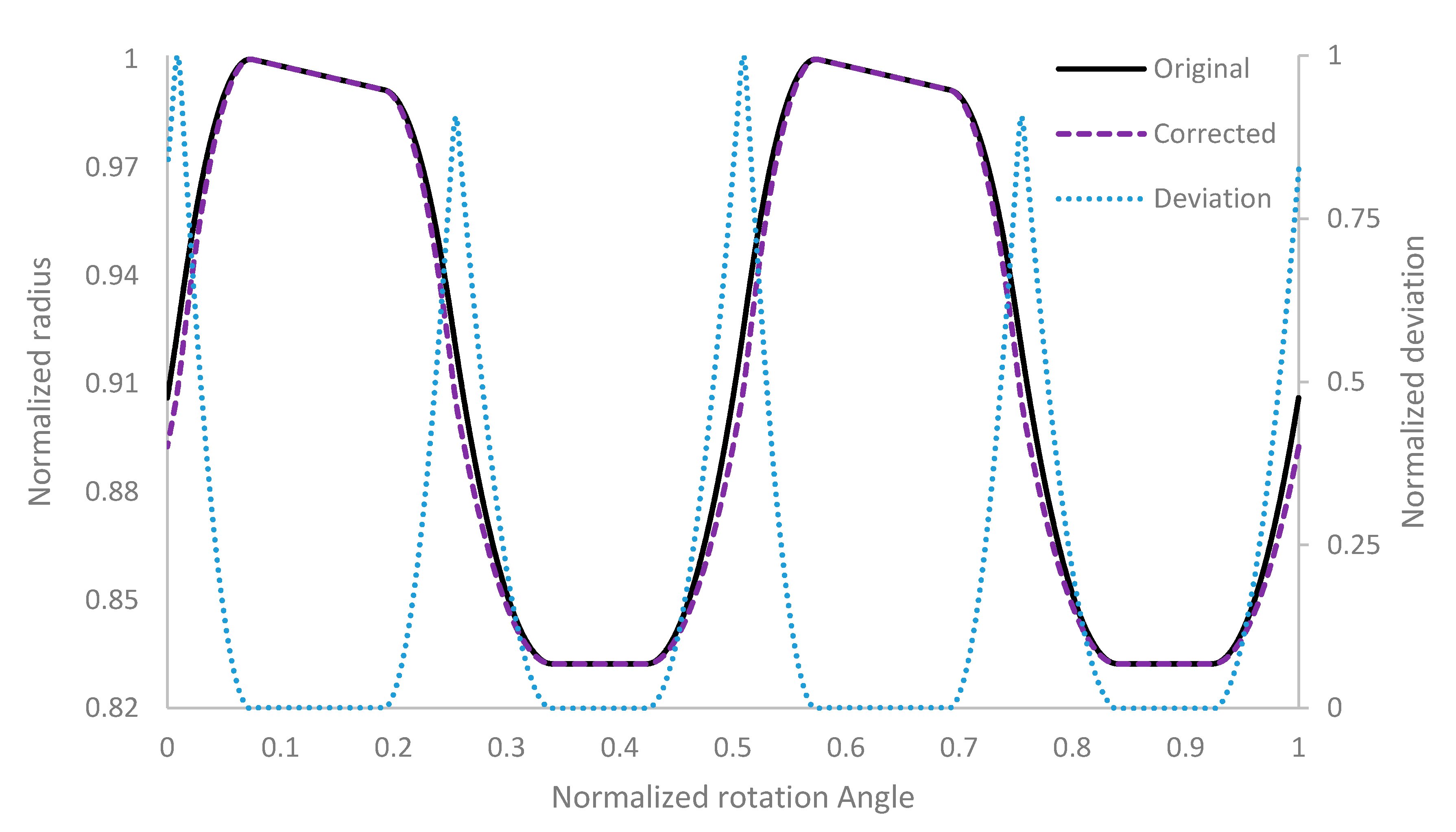
To obtain the velocity function, a table with the cylindrical coordinates of the points on a curve along the cam ring surface is written. The values of this table are normalized and plotted in
Figure 5 labeled as “Original”. For each vane, a rotating coordinate system with x-axis in radial vane direction is assigned. Subsequently, the radial velocity is interpolated at the vane middle axis from the table, depending on the angular position of the vane. Since the vane–cam ring contact point is not at the vane middle axis for all angular positions, the actual radial vane position at the middle axis differs from the position derived from the coordinate table (minus the approximation for the radial gap). Due to this deviation in the radial position of the vane, a correction of the radial velocity is mandatory.
To obtain the correct radial vane velocity, the original cam ring coordinates are corrected by an offset for each angular position, depending on the vane–cam ring contact point. For this purpose, the cylindrical coordinates are compared to the normalized coordinates of the vane tip curve at each angular position. Consequently, a correction value for the radial coordinate is computed for the current angular position if a smaller vane–wall distance is detected. As a criterion to detect if a correction is needed, the derivative of the vane tip radius and the derivative of the cam ring radius at the same angular position are used. If the derivative of the vane tip radius equals the derivative of the cam ring radius, no correction is needed. If the change in the radius of the vane tip curve is smaller than the change of the radius in the cam ring curve, the position of the cam ring curve is updated. This leads to a “Corrected” cam ring curve and new coordinates (
Figure 6), which are written to a table and are used to interpolate the correct radial velocity. The corrected curve and the difference of the radial position between the original curve and the corrected curve are shown in
Figure 5. Note that the deviation is exaggerated by factor four to make it visible. Another approach of how to calculate the cam ring contact curve is given by [
1,
17,
18].
In Star-CCM+, a morphing mesh approach and an overset mesh approach are available. In the present project, the morphing approach is favored since it showed lower computational effort and more robust simulations for this task. In the morphing approach, mesh nodes are shifted with an assigned velocity or tangential to boundaries. The vane tip and back vane boundary motion is prescribed by interpolating the corrected radial velocity at the specific angular position. The outer boundary of the displacement chamber mesh (largest radius of the rotating chambers in Figure 8) is morphed to the inner shape of the cam ring computer aided design (CAD) surface. These are the only boundaries in the pump, which perform a motion in radial direction. As a consequence, all other boundary motions can be modeled by only assigning a rotating motion, because no translation is needed.
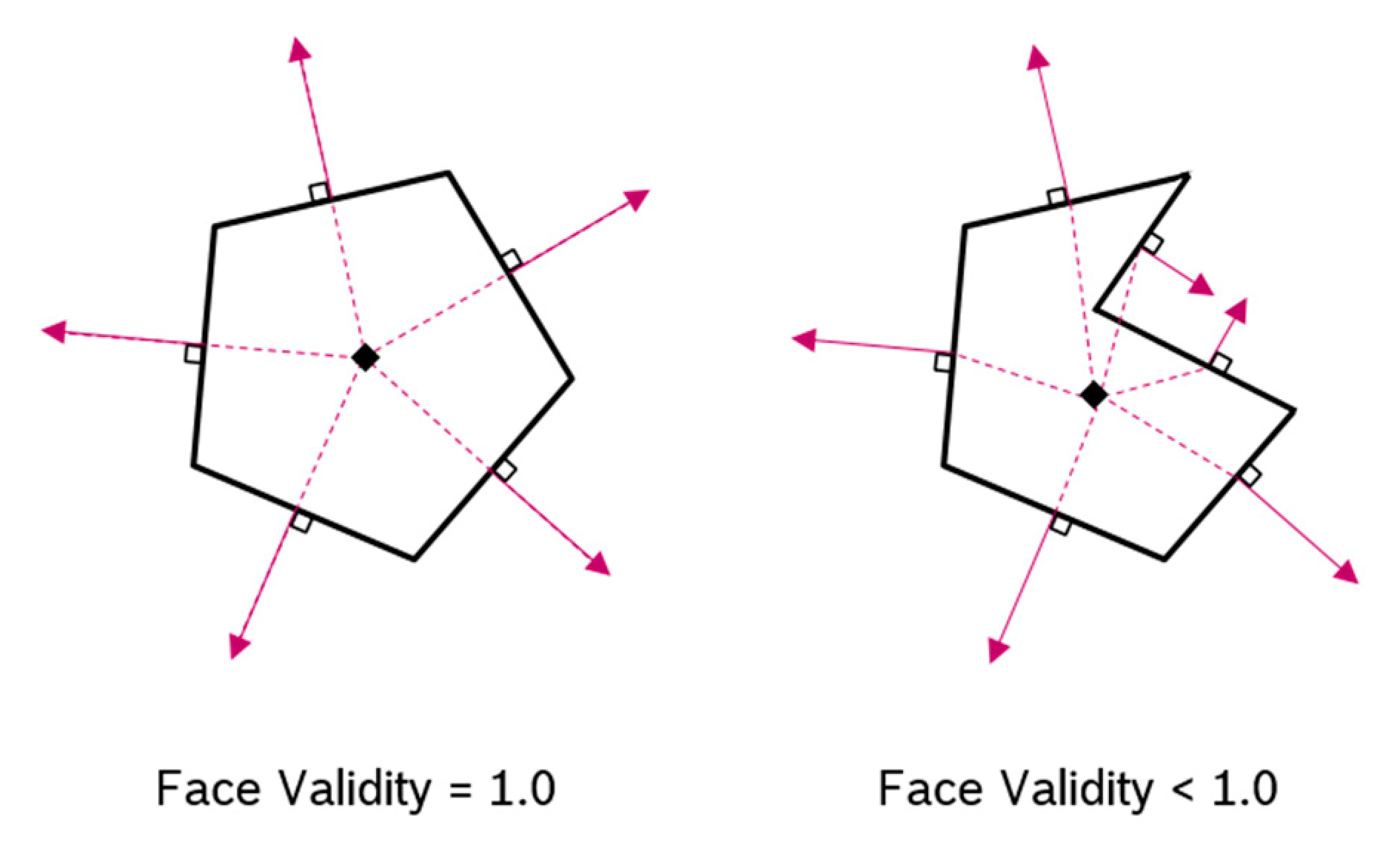
Depending on the accuracy of the morphing algorithm, the morphing of the mesh nodes leads to an accumulation of small dislocation errors during time. Additionally, the varying radial extend of the displacement chambers leads to an ongoing deformation of computational cells. With increasing simulation time, this results in a decrease in the mesh quality. This effect can lead to the occurrence of negative volume cells in the computational mesh, which cause the solver to abort. To reduce the mesh deformation and to avoid negative volume cells, a remeshing approach is introduced. This approach redistributes the mesh coordinates to obtain a mesh with less distortion. Subsequently, the solution is interpolated from the old to the new mesh and the calculation resumes on the new mesh. The event, which will trigger the remeshing, depends on the actual mesh quality. To detect a need for remeshing, the minimum face validity function predefined in STAR-CCM+ is chosen, because it was found that a negative volume cell will occur a few time steps after the minimum face validity drops below the value 1.0. Therefore, a remeshing is executed if the minimum face validity is lower than 1.0 for any computational cell in the domain. The definition of the face validity is given by STAR-CCM+. The face validity is 1.0, if all face normals point outwards of the computational cell (
Figure 7 left). In
Figure 7 on the right side, some face normals point towards the centroid. This indicates the computational cell is of a bad quality. If the face validity drops below 0.5, a negative volume cell will occur and cause the simulation to abort [
19].
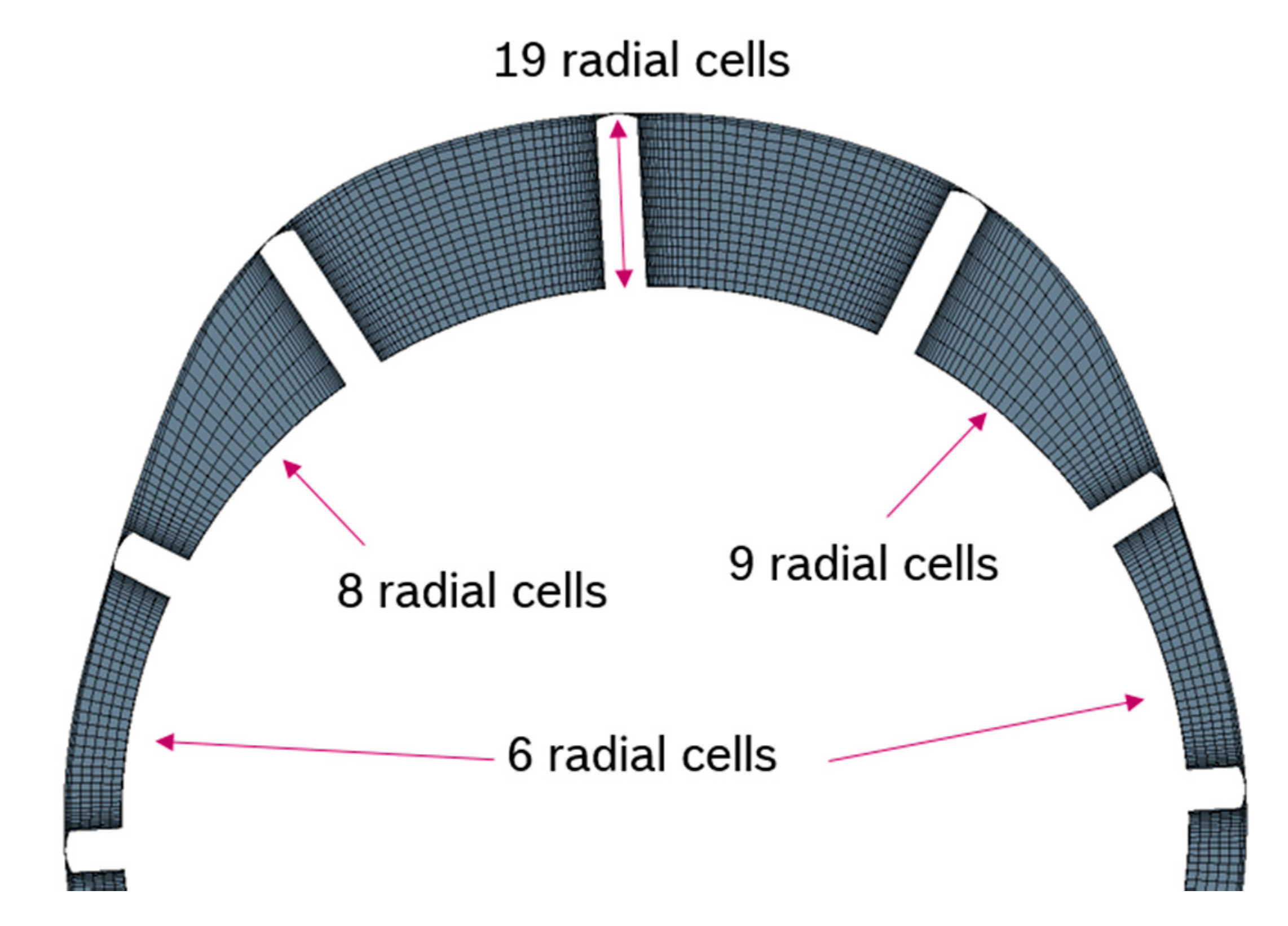
The remeshing approach is also used to reduce the number of computational cells in the radial direction depending on the radial extend of the displacement chamber (
Figure 8). This ensures a better mesh quality with respect to the aspect ratios.
The displacement chambers are connected by the radial gap (clearance between the vane tip and the cam ring surface) and by the axial gap (clearance between vanes/rotor and static parts). Typically, the size of the gap is about a few micrometers in positive displacement pumps [
4]. In the simulation model, the radial gap is assumed to have a size of 5 μm, while the axial gap has a size of 40 μm. The size of the radial gap is an assumption because no measurements of the gap size exist. Previous simulations showed a good agreement of the volumetric efficiency and the pressure pulsations with experiments for a radial gap size of 2 μm to 5 μm. The size of the axial gap on top and bottom of the displacement chambers is usually derived by the manufacturing dimension. The meshing details of the gaps are summarized in
Table 1.
As boundary conditions, a pressure load (delivery pressure) is applied to the pump outlet and a rotational speed is assigned to the rotating mesh. At the inlet of the pump, the pressure is set to 1 bar absolute pressure. Thus, the mass flow rate of the pump is obtained as a result of the simulation. In the present work, the fluid is assumed to be hydraulic oil at a temperature of 80°C. The material properties are listed in
Table 2.
In the present work, cavitation and other two phase phenomena are not considered and the fluid is assumed to be isothermal. Experiments, which are available for rotation rates up to 3000 rpm, show that these simplifications are justified. Additionally, the fluid is assumed to be incompressible at low rotational speeds. To compare different operation points of the pump it is decided that the simulations use the same angular resolution. Therefore, the time step of simulations is calculated by
where n is the rotational speed, Δt is the time step and Δφ the desired angular resolution. The simulation is performed as an unsteady RANS simulation and uses an implicit scheme. For the turbulence modeling, the k-ε turbulence model is chosen. In total, the cell count of the model is 4.5 million. To ensure a good mesh quality, remeshing of the rotor mesh takes place at least every 30° rotation angle. Further remeshing events to avoid negative volume cells are triggered by the minimum face validity as explained above. The simulation results of this model are investigated in the next section.
4. Results
In this section, the results of the simulations and the measurements of the displacement chamber pressure are analyzed and compared. First, the impact of different numerical parameters (e.g., the number of inner iterations and the angular resolution) on the predicted displacement chamber pressure is investigated. Subsequently, simulation results for different operating conditions are compared to measurements. The measurement data as well as the simulation data of the displacement chamber pressure are averaged making use of the 360° periodicity of the rotary motion. For the measurement, the mean value of ten complete revolutions of the pump is used. This is done to avoid singular effects in the displacement chamber pressure due to e.g., air in the pump or dirt particles in the oil. In the simulation, also small differences in the displacement chamber pressure are detected for different chambers (Figure 17). This is most likely caused by the vane motion approach, which can lead to small fluctuations about 1e–7 m in the radial gap size. To obtain a comparable pressure signal, monitor points are placed in three succeeding displacement chambers. Subsequently, a mean value of the pressure signal of these three monitor points is computed.
For this purpose, the pressure signal is shifted by Δγ, to get coherent signals as derived by Equation (2). In this equation Δγ is the angular extend of a displacement chamber and N is the number of vanes. Here, the shift , because the investigated pump has twelve displacement chambers. This procedure saves computational time, because less rotations of the pump need to be simulated to get a mean value.
4.1. Preliminary Investigation of the Simulation Setup
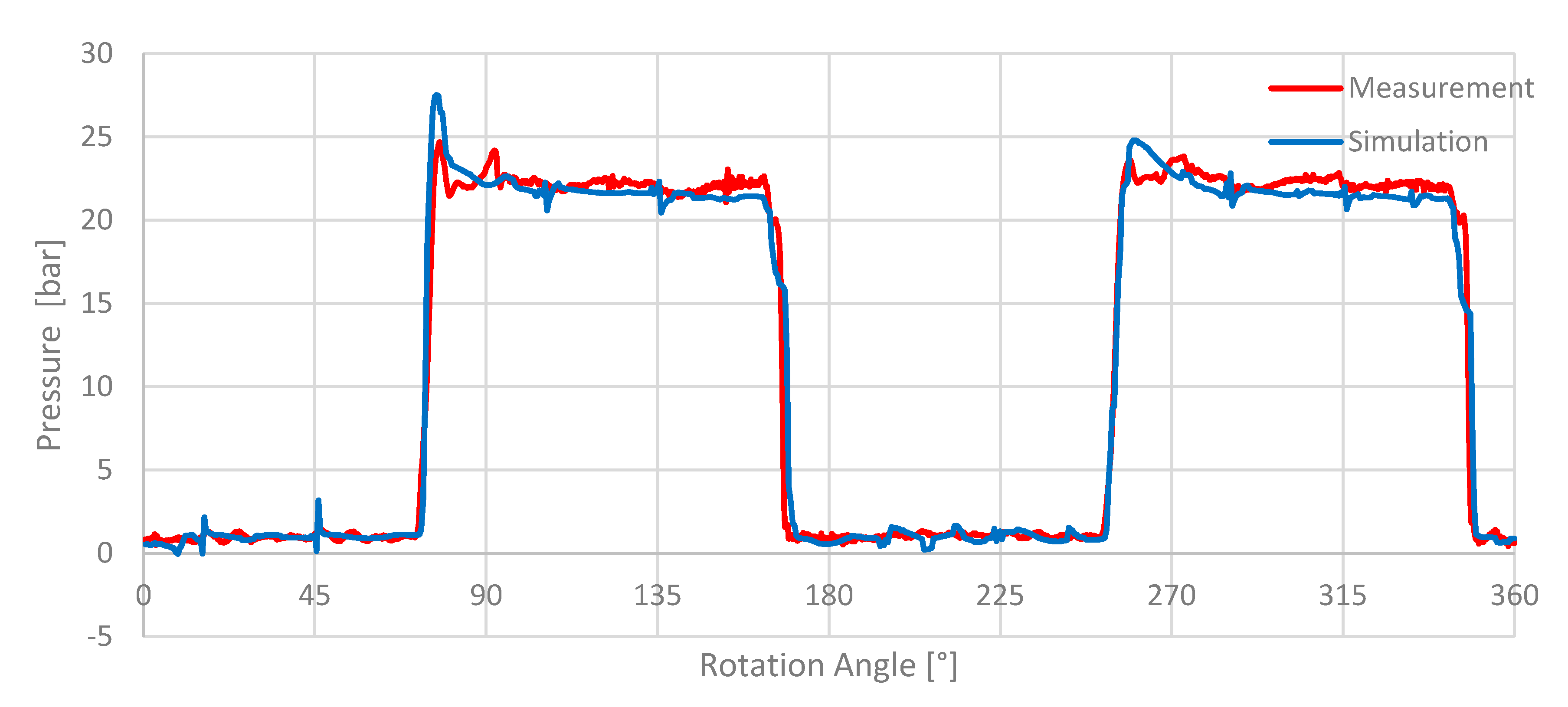
The simulation result of the displacement chamber pressure for a rotational speed of 2000 rpm and 20 bar delivery pressure is compared to the experimental data in
Figure 9.
Figure 9 shows that the characteristic internal chamber pressure profile of the pump is well resolved by the CFD model. The mean pressure at the suction port is predicted in good agreement with the experiments and the mean pressure at the delivery port matches with the experimental data. The small deviation that can be observed is most likely caused by the chosen outlet pressure boundary condition in the simulation.
The strong fluctuations of the pressure during the suction process at 16° and 46° are caused by the incompressibility of the solution. Hence, the pressure pulsations can travel through the system without any relaxation. These effects are also visible in the high pressure section at different positions (106° and 136°) and are caused by the pressure surge of the subsequent displacement chambers (Figure 17). These pressure fluctuations are also visible in the measurement. However, the magnitude and shape differs from that of the predicted pressure signal.
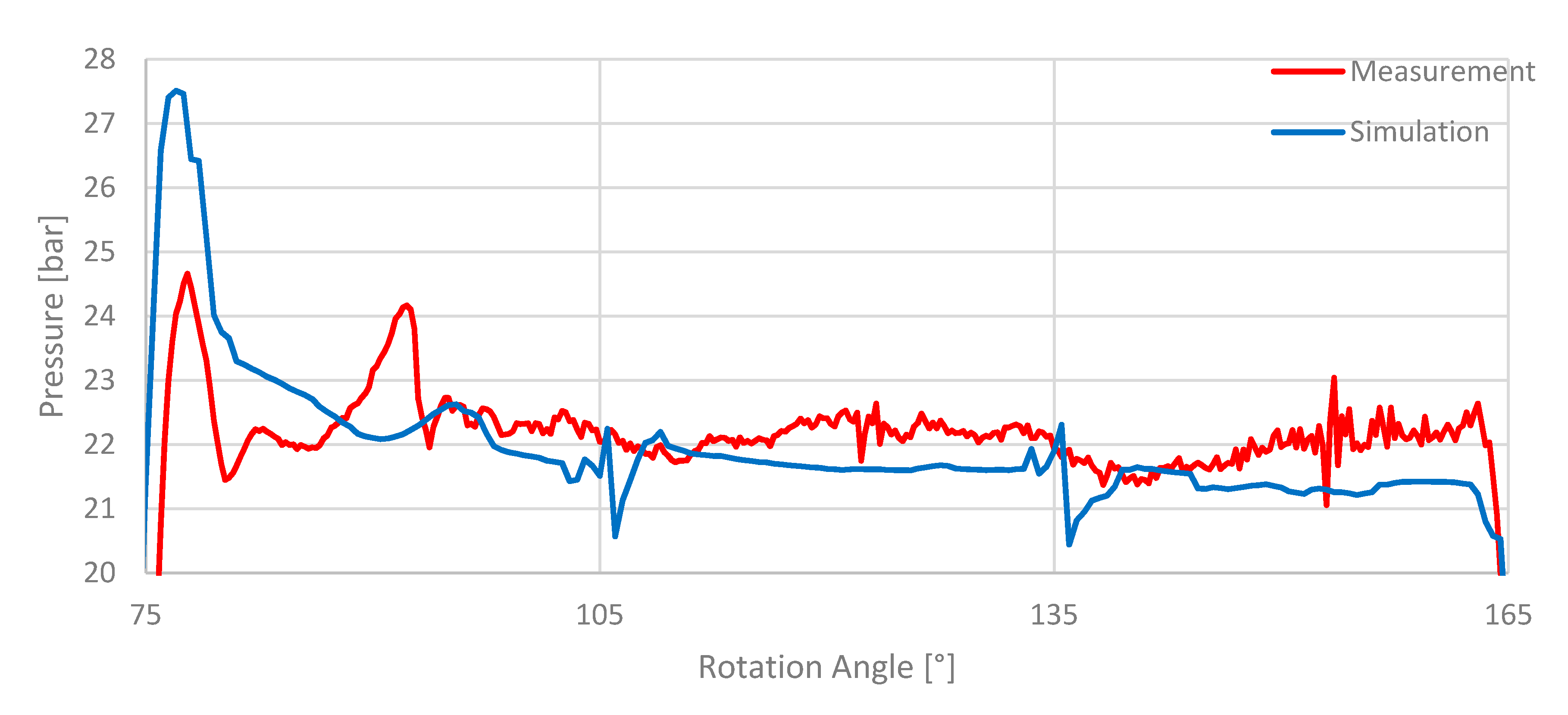
This can also be traced back to the pressure surge in the displacement chamber during the compression, which is overpredicted in the simulation. The small and high frequency fluctuations visible in the measurement are not captured in the simulation. A more detailed view of these fluctuations is given in
Figure 10.
Possible causes for the occurrence of these fluctuations are vibrations of pipes, vibrations induced by the test bench powertrain, pressure wave reflections in the hydraulic system and measurement noise. These effects cannot be not resolved in the CFD model and their impact is hardly quantifiable.
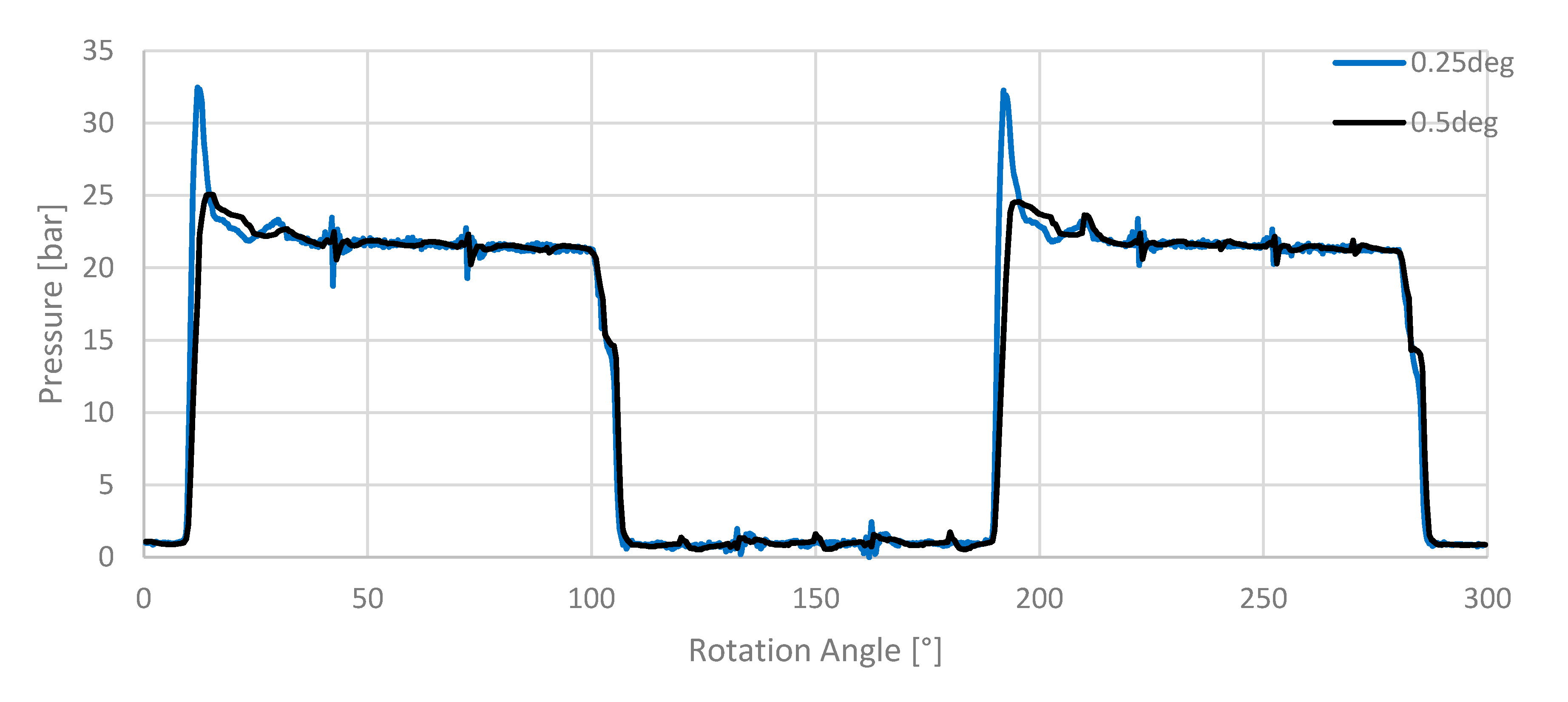
It was found that the angular resolution has a high impact on the overprediction of the pressure surge arising during the transition from the suction to the delivery port (77° and 260°).
Figure 11 shows the simulation results for an angular resolution of 0.5° and for an angular resolution of 0.25°. It is clearly visible that the simulation with 0.25° angular resolution leads to an increased pressure surge. This pressure surge is limited in time and the remainder of the pressure curve is not affected by an increase in the angular resolution. Since the angular resolution of 0.5° already shows reasonable results and the simulations are less computational expensive, the angular resolution Δφ is set to 0.5° for all simulations.
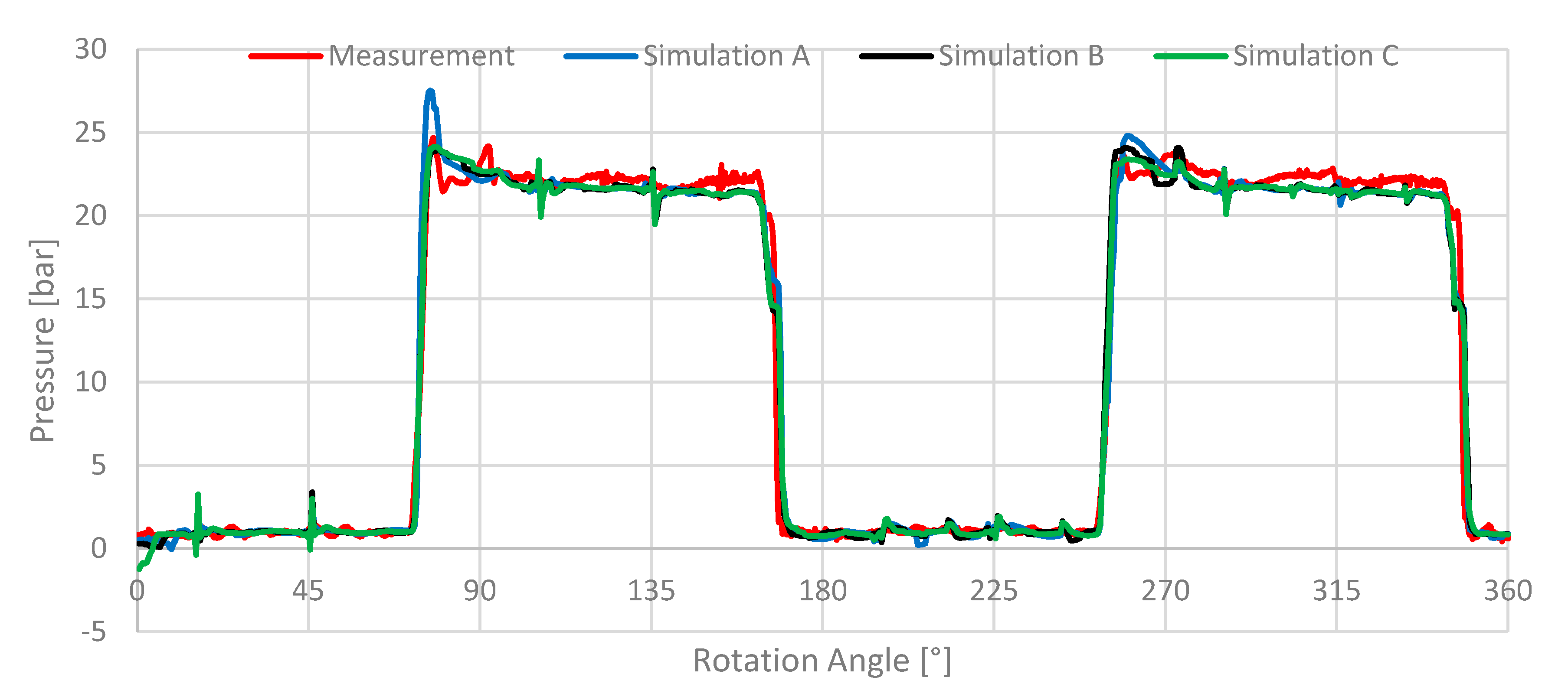
In the next step, the number of inner iterations is investigated. Therefore, the pressure under-relaxation factor is also adjusted. This is done to achieve a better convergence. It also affects the pressure curve, especially during the transition of a displacement chamber from the suction to the pressure port, where the highest gradients occur. This leads to a better agreement of the measured and the simulated pressure curve. The different simulation parameters are given in
Table 3. The results for these simulations and the impact on the pressure signal are pictured in
Figure 12. If only the inner iterations are adjusted, without changing the pressure under-relaxation factor, the solution starts to oscillate around a mean value leading to higher residuals. In this case, the correct solution is not obtained since the change per iteration is too high to get closer to the correct solution.
This figure shows that the use of ten inner iterations for the simulation is sufficient to achieve a reasonable convergence. A further enhancement to 20 inner iterations has almost no effect on the solution, leading only to a higher computational effort. Therefore, all following simulations were performed using 10 inner iterations and a pressure under-relaxation factor of 0.2.
4.2. Influence of Rotational Speed
After the simulation shows good agreement with the measurement at a rotational speed of 2000 rpm and 20 bar, the chamber pressure at other rotational speeds and different delivery pressures is examined. First, the rotational speed is varied at a constant delivery pressure of 20 bar at the delivery port.
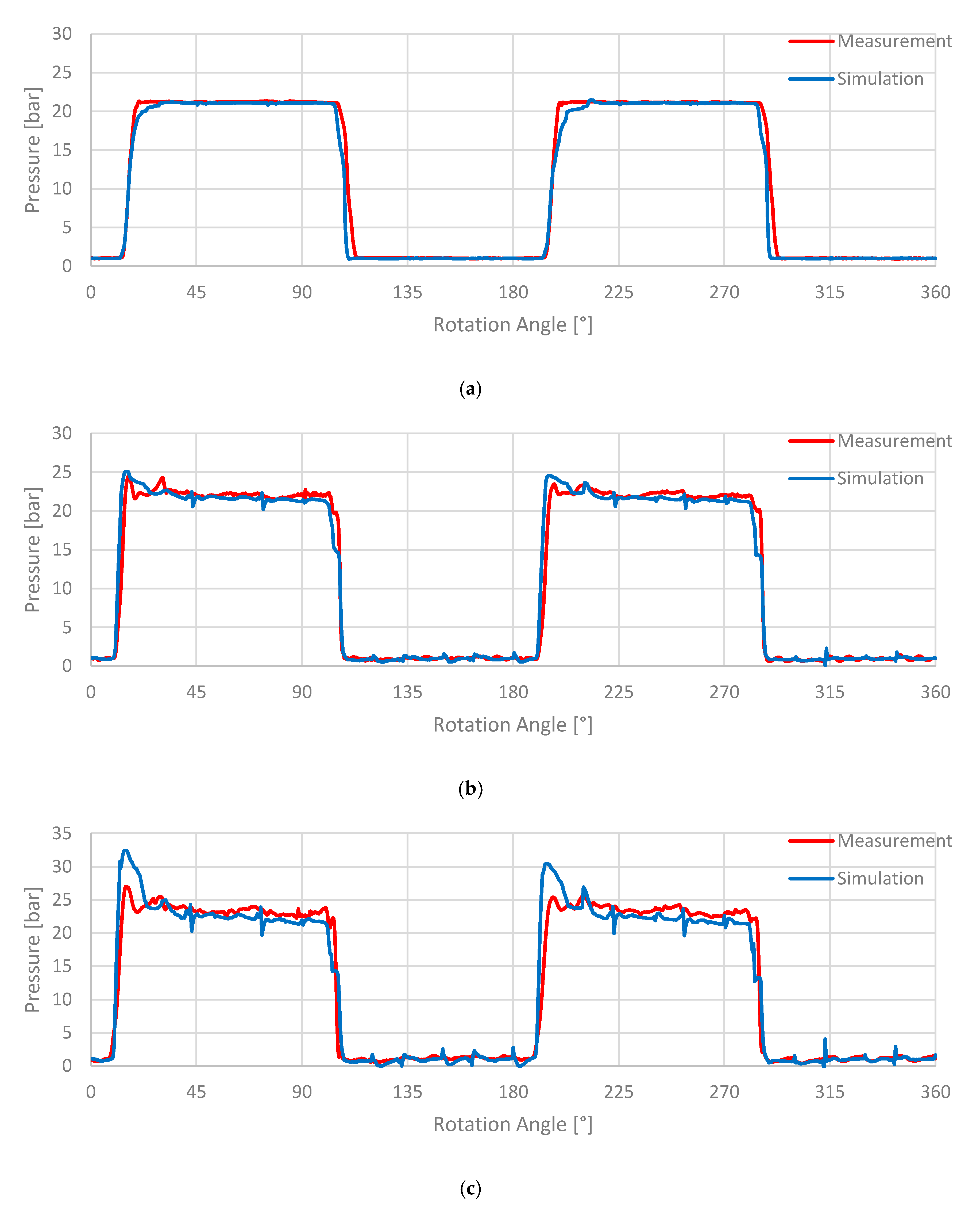
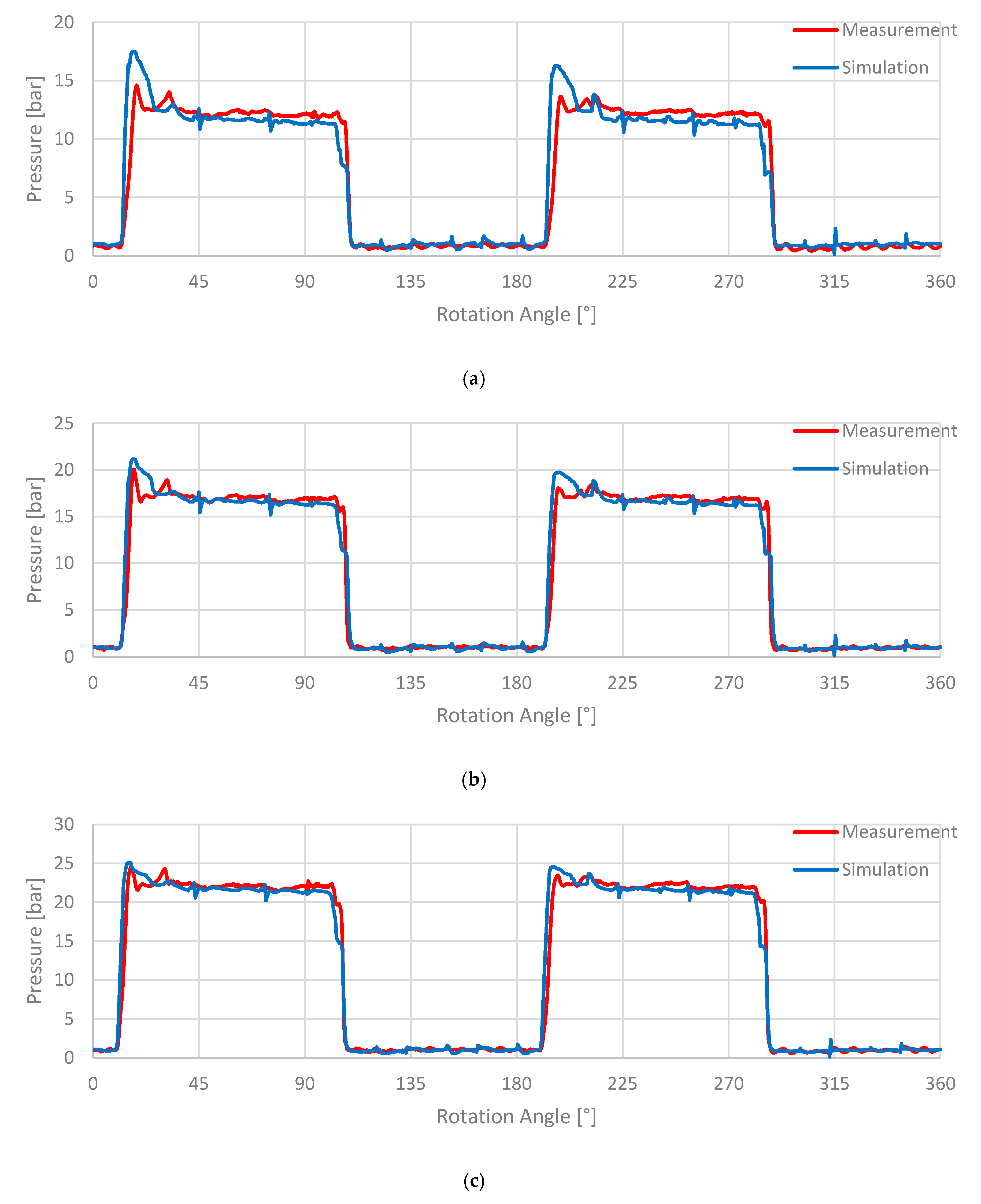
As can be seen in
Figure 13, the rotational speed has a high impact on the pressure in the displacement chamber. At a rotation rate of 500 rpm as shown in
Figure 13a, simulation and measurement are in good agreement, except the fact that the precompression and compression of the displacement chamber is underpredicted when the displacement chamber connects to the delivery port (10° to 32° and 190° to 212°). The simulation result for 2000 rpm can be seen in
Figure 13b. Again, the simulation shows a good agreement with the measurement. Regarding the high pressure area (pressure surge and pressure plateau), while the displacement chamber is connected to the delivery port, it is visible that the fluctuations of the pressure are not captured correctly in this area. The pressure surge increases faster and is predicted over a longer angular range than in the measurement (9° to 24° and 189° to 204°). Additionally, the simulation detects a small pressure drop in the pressure plateau as the displacement chamber is passing the delivery port (15° to 100°; 195° to 280°). This pressure drop is not or less noticeable in the measurement. The pressure starts to drop nearly at the same angular position in simulation and measurement (100°; 280°) as the displacement chamber disconnects from the delivery port. However, the predicted pressure drop in the simulation is too high. About 2.5° later, the pressure in the measurement shows again a small peak (102.5°; 282.5°). This effect is also visible in the simulations in the form of a delay in the pressure drop. After this delay, the pressure curves of the measurement and simulation match again. The observed effects become even more distinct for the simulation at a rotational speed of 3000 rpm (
Figure 13c). At this rotational speed, the simulation again overpredicts the pressure surge during the compression. This may be caused by the assumption of an incompressible fluid. At a speed of 3000 rpm, compressibility effects may not be negligible anymore.
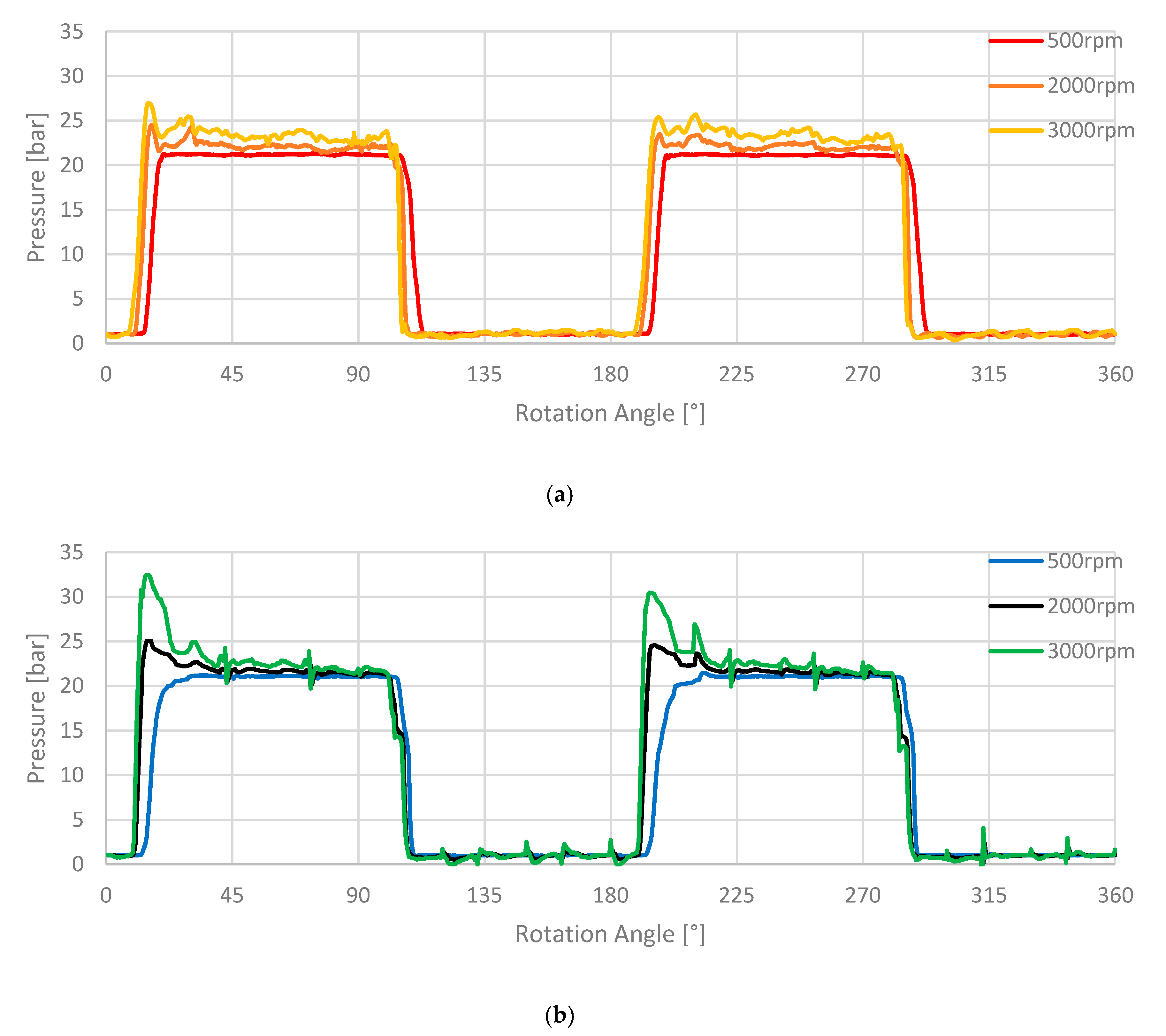
Regarding the effects of different rotational speeds on the pressure curves of the pump, the measurements (
Figure 14a) show that with an increased rotational speed, the amplitudes of the pressure surge and the pressure pulsations in the high pressure section become more significant. This effect could also be captured in the simulations (see
Figure 14b).
4.3. Influence of Delivery Pressure
In the second step, the delivery pressure is varied while the rotational speed is held constant at 2000 rpm. The results for these simulations are shown in
Figure 15.
Figure 15a shows the result for a delivery pressure of 10 bar. It can be observed that the pressure surge (18° and 198°) during the precompression is overestimated. A pressure drop during the entire high pressure section is observed in the simulation, which is not seen in the measurement (compare
Figure 13c, investigation of rotational speed). Furthermore, the pressure at the end of the high pressure section drops too early (same effect as in the previous investigation). If the delivery pressure is increased to 15 bar as displayed in
Figure 15b, the overprediction of the pressure surge (18° and 198°) at the beginning of the high pressure section is becoming less severe. In
Figure 15c, the predicted pressure surge is further reduced as the delivery pressure is increased.
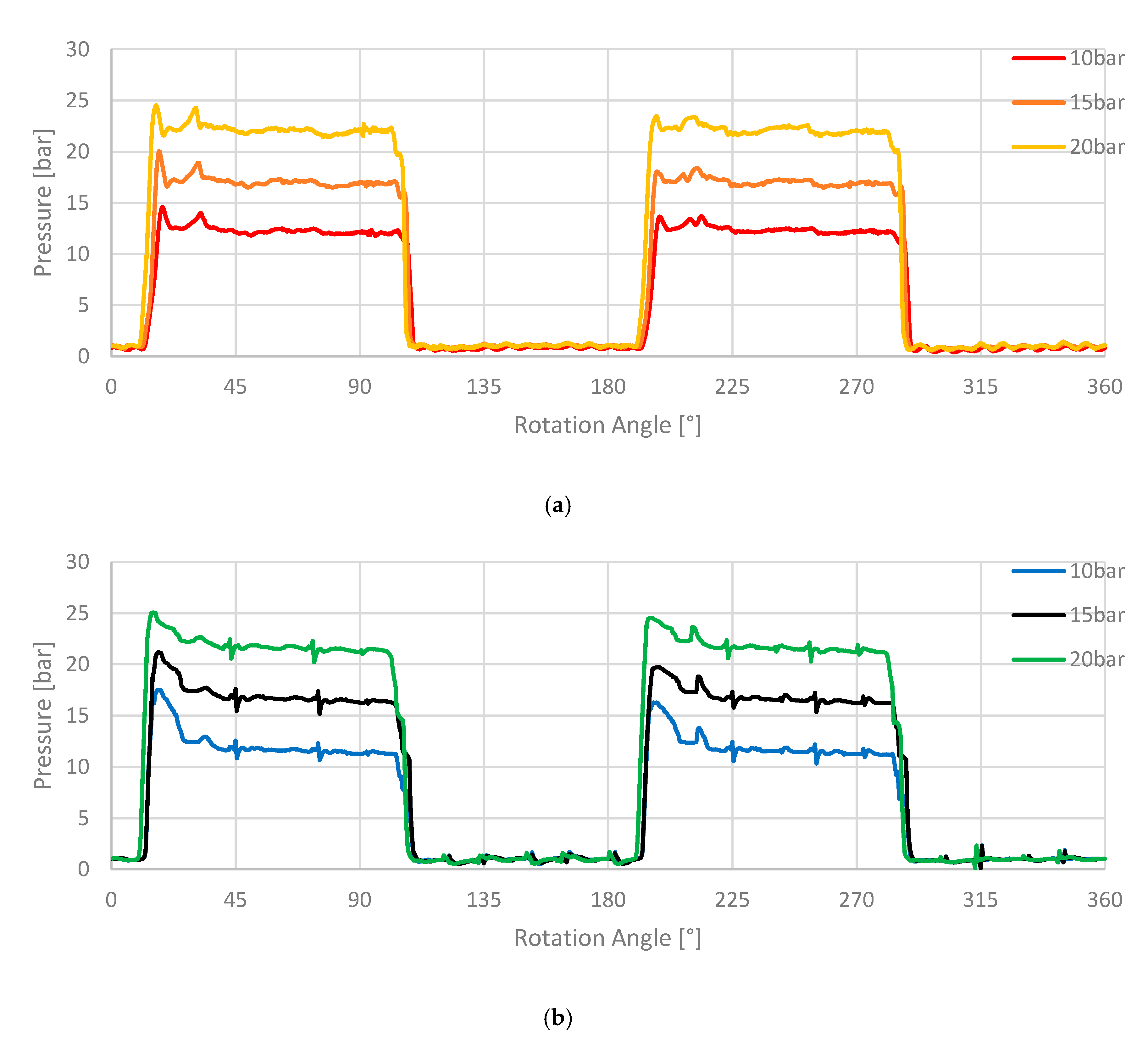
Figure 16a shows the characteristic effects of an increased delivery pressure on the displacement chamber pressure. The measurement shows that a higher delivery pressure causes sharper pressure rises and drops during the transition of a displacement chamber from the suction to the delivery port, or vice versa. The amplitudes of the pressure surges and the fluctuations in the high pressure section are not affected by a higher delivery pressure in the measurement. This is an expected effect, since the amplitudes of these pulsations are only affected by the volumetric flow, the inertia of the fluid and the geometry of the pump, which then lead to pressure drops and rises. In the simulation in
Figure 16b, a reduction in the pressure surge is visible. This effect is related to the higher pressure gradient between pressure and suction port. A higher pressure gradient leads to higher volumetric flow rates through the radial and axial gaps as well as through the groove. These effects result in a pressure rise of the internal displacement chamber pressure before connecting to the delivery port. This further leads to a lower pressure gradient and pressure surge when the displacement chamber fully opens to the delivery port. Currently, it is not clear why this effect is not observed in the measurements. This could be due to uncertainties regarding the estimation of the gap size in the simulation or due to the assumption of incompressibility, which is causing faster pressure compensating effects. Additionally, in the measurements, the pressure load in the back vane volume influences the radial gap size. The back vane volume is connected to the delivery port and, subsequently, an increased delivery pressure leads to higher back vane forces resulting in a reduced radial gap size if the same rotational speed is applied. In the simulations, the radial gap size is a user defined parameter, which is assumed to be constant at a size of 5 μm for all simulations. A reduced radial gap size at higher delivery pressures could compensate the effect of a higher volumetric flow rate through the radial gaps, preventing an additional pressure rise in the displacement chamber before connecting to the delivery port. This effect could cause the pressure surge in the measurement to be constant for different delivery pressures. However, this effect needs further investigations.
4.4. Further Investigations
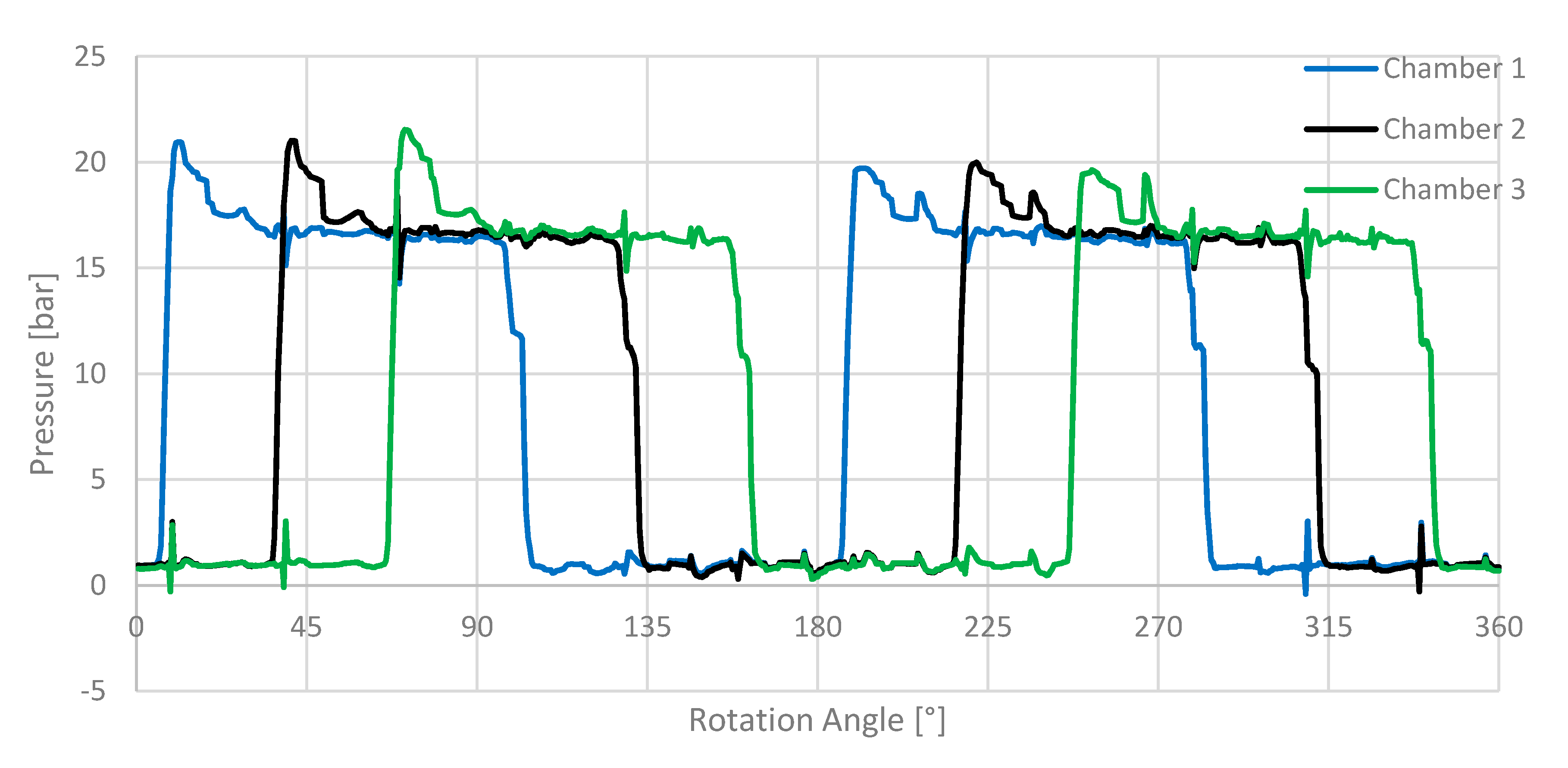
In the measurement, it is only possible to monitor the pressure in one displacement chamber, due to the limited space in rotor and shaft. In the CFD simulation, monitor points can be placed virtually everywhere. The pressure signal of monitor points in three succeeding displacement chambers is pictured in
Figure 17. It is clearly visible that the pressure pulsations in the high pressure section of the preceding displacement chamber are affected by the pressure surge of the following displacement cambers. The pressure pulsations caused by this interaction are also visible in the measurements (
Figure 16a).
Therefore, an idea to reduce the pressure pulsations in the high pressure section of a displacement chamber is to reduce the pressure effects of a displacement chamber, which can be associated to an effect of another displacement chamber. In particular, the pressure surge during the transition from the suction to the delivery port of chamber 2 and 3 match with fluctuations in the pressure of chamber 1 (40°, 70°, 220°, 250°). The distance of these recurring effects is related to the number of displacement chambers and the resulting angular extend of a displacement chamber. For the investigated pump with twelve vanes, this distance is 30° (see formula (4)).
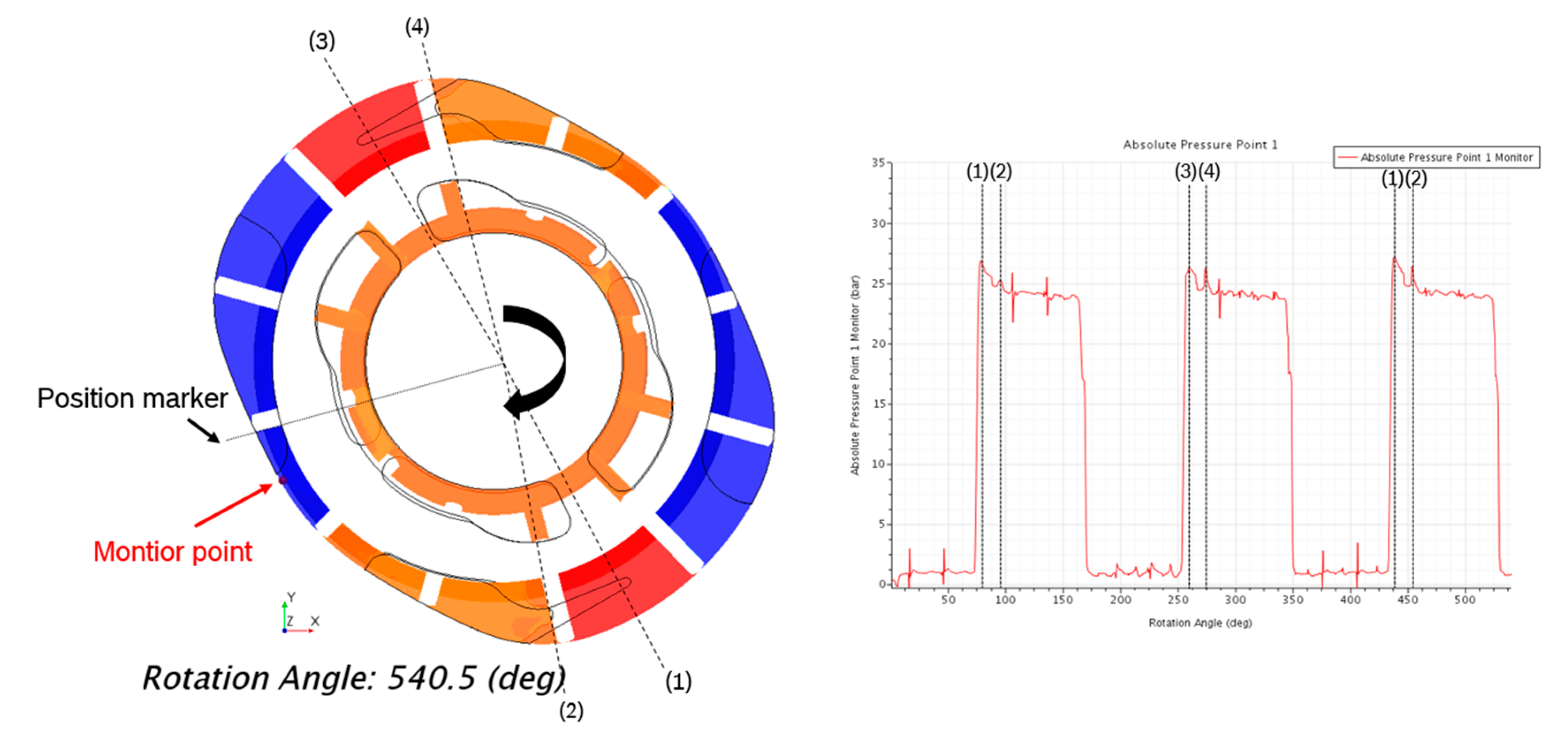
Additionally, the simulation allows to track the exact position of the vanes in the pump and to compare the results to the recorded displacement chamber pressure. This helps to identify when and why the pressure surge is occurring and to find countermeasures. In
Figure 18, the monitor point for the displacement chamber pressure and the rotating parts of the geometry are visualized in the simulation. The positions (1) to (4) mark the positions of the inner vane surface of the preceding vane for the displacement chamber containing the monitor point (position marker), when a recurring pressure surge rises.
Position (1) is the angular position when the initial pressure surge during the transition from suction port 1 to delivery port 1 occurs. At this position, the displacement chamber with the monitor point has already a small connection to the delivery port 1 via the groove and the pressure is at the highest magnitude. At position (2), the displacement chamber gets a direct connection to the delivery port (before it was only connected by the groove), which leads to a smaller second pressure surge. The same effects are visible at positions (3) and (4) for delivery port 2. This indicates that a groove with a longer angular extend, or a higher volume can reduce the first pressure surge at this rotational speed. Adding a groove to the delivery port can help to avoid the second smaller pressure surge. The reduction in these pressure surges should lead to a reduction in the noise radiation of the pump. However, this needs to be validated by further simulations and experiments.
5. Conclusions
In the present work, the internal displacement chamber pressure of a rotary vane pump has been investigated. For this purpose, a CFD simulation model for rotary vane pumps has been introduced. The CFD model was setup in the commercial software STAR-CCM+. The developed simulation model uses a morphing approach with a prescribed vane motion and a fixed radial gap size of 5 μm. To ensure a good mesh quality and avoid negative volume cells, a remeshing approach is applied. It was shown that the results of the simulation model are in good agreement with the measurements and that the internal displacement chamber pressure can be captured quite well.
From the investigation of the simulation model, it has been derived that the angular resolution Δφ has a certain impact on the predicted pressure surge height during the transition of the displacement chamber from the suction to the delivery port. However, this effect is limited in time and the predicted pressure level at the delivery port is captured correct in simulations using a Δφ of 0.5°. Therefore, an angular resolution of 0.5° is a good tradeoff between computational effort and accuracy and hence is chosen for all simulations. Additionally, a number of ten inner iterations per time step and a pressure under-relaxation factor of 0.2 is suitable to achieve a reasonable convergence for this kind of simulation.
The investigation of the internal chamber pressure at different operating conditions showed that an enhanced rotation rate as well as an increased delivery pressure has a big impact on the characteristic pressure curve. The measurements and simulations of an increased rotation rate showed a trend to higher pressure surges at the transition of a displacement chamber from the suction to the delivery port. Additionally, the magnitude of pressure fluctuations around the delivery pressure in the high pressure section are increased when the chamber is connected to the delivery port. Consequently, the shape and amplitudes of the displacement chamber pressure signal changed with an increasing rotational speed. These effects are caused by the inertia and turbulence of the fluid, which lead to increased flow fluctuations at higher velocities.
The simulation with 3000 rpm showed a higher deviation between the measured and the computed pressure than for the other cases. It is likely that at this rotation rate, the assumption of incompressibility is no longer valid. This point needs further investigations.
In contrast to an increased rotational speed, an enhanced delivery pressure leads to a reduction in the pressure surge during the transition of the displacement chamber from the suction to the delivery port in the simulations. This effect is caused by the higher pressure gradient between the delivery port and the connecting displacement chamber for higher delivery pressures. However, this effect was not observed in the measurements, where the shape and the magnitude of the pressure surge and the fluctuations in the pressure section did not change with an increased delivery pressure. Only the height, as well as the sharpness of pressure rise and drop at the beginning and the end of the pressure section, were affected in the measurements.
Overall, the measurements and simulations showed the same tendencies, and initial conclusions to optimize the pressure ripple and to reduce the noise radiation of the pump have been derived. From the simulation, it could be observed that the fluctuations in the high pressure section are affected by the pressure surges of subsequent connecting displacement chambers. This was verified by the measurements, which showed arising pressure surges at the same angular positions during the transition of a displacement chamber from suction to delivery port. Therefore, it is now possible to derive the positions of occurring pressure surges related to the pump geometry from the simulation. However, the magnitude and the shape of these pressure surges are difficult to capture in the simulations and still require further enhancement.
