Article

Novel Dynamic Resistance Equalizer for Parallel-Connected Battery Configurations

School of Electrical Engineering, University of Ulsan, Ulsan 44610, Korea
*
Author to whom correspondence should be addressed.
Energies 2020, 13(13), 3315; https://doi.org/10.3390/en13133315
Submission received: 1 June 2020 / Revised: 25 June 2020 / Accepted: 26 June 2020 / Published: 29 June 2020
(This article belongs to the Section D: Energy Storage and Application)

Abstract

:
As the number of parallel battery connections in an energy storage system is increased to extend the energy capacity and second-life batteries are actively adopted, the battery is more prone to cell inconsistency issues. The difference in the internal impedance and the mismatched state-of-charge accelerates the self-balancing effect between the parallel branches to reduce cell utilization and eventually results in harmful effects, both to the lifetime and to the safety of the batteries. However, conventional methods only partially mitigate the parallel inconsistency issue. This paper proposes a dynamic resistance equalizer for parallel-connected battery configurations to improve equalization performance. The optimal design procedure is also presented to minimize the power loss and equalization time. The overall performance is experimentally verified by a sequence of tests for a Li-ion battery in a 2S-4P configuration. The experimental results show that the proposed method dissipates less external power loss than the fixed resistor equalizer and less internal loss than the conventional sequencing method. When both total loss and balancing performance are considered together, as the number of series connections increases, the merits of the proposed method stand out. This is verified by additional hardware-in-the-loop tests, presenting a fascinating feature for most practical battery applications.

1. Introduction

In an effort to prevent climate change, the transportation industry is becoming increasingly electrified [1,2]. However, the battery packs of electric vehicles (EV) have a limited lifespan and usually need to be replaced when the state-of-health decreases to 70–80% [3]. Although some disassembling and recycling procedures have been proposed, as in [4,5], it is not yet economically feasible. Meanwhile, the second-life battery energy storage system (SL-BESS) is a promising solution to re-use the retired battery packs [6]. However, the difference in the internal impedance, capacity, and electrical characteristics between cells—so-called cell-inconsistency—becomes more serious in the second-life battery application.
In most energy storage systems, like EV or SL-BESS, battery cells are connected in series to reach the operating voltage specification. However, due to the imbalance in the electrochemical impedance, cell-inconsistency issues arise, and thus, various cell-balancing techniques for the series-connected battery cells have been developed, which can be classified into passive and active techniques [7,8]. Due to energy dissipation, passive cell-balancing methods have low efficiency and speed [9], but are cost-effective and less complex compared to active methods. On the contrary, active techniques employ a switched inductor [10], a switched capacitor [11], or a dc-dc converter [12] to ensure better equalization performance and efficiency.
Nowadays, due to the strong demand for higher battery capacities in the market, some manufacturers are working on larger format cells, while there are also requirements for an increased number of parallel connections. For example, the Nissan Leaf EV consists of two cells in parallel [13], the Chevrolet Volt plug-in hybrid EV utilizes three parallel-connected cells [14], and an energy storage system for a data center has a much larger number of battery cells connected in series and parallel [15].
Many researchers have reported that cell-inconsistency in parallel battery configurations can cause serious problems, as in the series case. If the open-circuit voltages of the batteries are different, there are continuous currents flowing across branches to balance the terminal voltage of parallel connection even in idle mode, when the battery is not exchanging any energy with the external source or load, which is called the self-balancing effect. Because the internal impedance of the battery is small, the amplitude of the self-balancing current is large and generates additional cell-heating and accelerates the battery aging. The different voltage drops in the different internal impedances make an unequal equilibrium open-circuit voltage in the battery cells in parallel, which eventually causes the unbalanced SOC even after the self-balancing process. As a result, when the paralleled battery is charged or discharged without any cell balancing scheme, it could cause the over-charging or over-discharging problems [16,17,18,19]. The experiments in [20] show that the battery is internally shorted during the over-discharge process in the parallel configuration.
Conventionally, the simplest method to prevent this issue is cell-binning or screening by measurements, which allows only cells with similar characteristics to be connected, as in Figure 1a. However, it requires an additional step of classification but does not always guarantee good performance, since the impedance of the cells tends to drift further, especially in SL-BESS applications [21]. As an alternative, sequencing switches can be attached to equalize the SOC (as in Figure 1b) [22,23,24], where the switching decision is made based on the SOC information of the cells. However, continuously pulsating currents increase the internal power loss inside batteries. On the other hand, Kuo et al. [25] proposed a passive method to distribute the currents evenly using a fixed balancing resistor, as in Figure 1c. However, this mechanism neither provides equalization performance nor cell utilization when the initial conditions of the battery cells are substantially different. The most serious problem related to this method is the considerable power dissipation in the balancing resistors.
While the conventional methods only partially mitigate the problem, this paper proposes a novel equalizer for the parallel-connected battery configuration to provide a viable and acceptable way to solve the inconsistency issue. Since the basic concept was originally presented in [26], we have extended it by appending operational analysis, design optimization, and more experimental verification in this paper. The equalizer topology is described in Section 2, analysis of the operation and the optimal design guidelines are suggested in Section 3, verification is presented in Section 4, and conclusions are made in Section 5.

2. Proposed Equalizer

The proposed circuit in Figure 2a utilizes two resistors and one switch per branch to construct a dynamic resistance equalizer (DRE). The bi-directional converter is used to regulate the output of the battery system in discharging mode or charge the battery cells in charging mode. By controlling the switches, S1, S2 and S3, the effective series impedances of the branches are adjusted to control the current flow in each branch. The switching decision is made based on the SOC level of the cells which can be estimated by various reported estimation methods [27]. In this paper, a Coulomb counting is used to estimate the SOCs where the equalization resistor R1 concurrently serves as a current sensor. However, other SOC estimation methods can be merged into this topology. The flowchart of the equalization algorithm is shown in Figure 2b, where the switching decision is different for the charging and discharging processes:
The operation process is divided into multiple equalization cycles with a period of T = T m + T h o l d , where Tm is the required time to measure the cell parameters for SOC estimation and Thold is the holding time to keep the switching pattern. During Tm, according to the current direction, the battery management system (BMS) detects whether the process is in the discharging or charging mode, the SOC comparison algorithm identifies the lowest SOC cell (in case of the discharging mode), pmin, or the highest SOC cell (in case of the charging mode), pmax, and the maximum SOC difference (MSD) is calculated to make the switching decision. If the MSD is higher than a pre-defined value, ΔSOCset, the corresponding switch in the highest SOC cell (in charging mode) or the lowest SOC cell (in discharging mode) is turned off while the other switches are kept on. As a result, the impedance of the chosen branch becomes higher than the others, which reduces its branch current. By discharging/charging the battery cells with such a controlled branch impedance, the SOCs of the cell are step-by-step equalized. When the MSD becomes lower than ΔSOCset, all switches are turned on to distribute the current evenly and minimize the power loss in balancing resistor. The switching pattern is held during Thold before another equalization cycle starts.

3. Equalization Process Analysis and Design Optimization

3.1. Equalization Process Analysis

Obviously, there is a trade-off between the equalization performance and the power loss in the equalization resistor, both of which are dependent on the design of R1 and R2. To analyze the power loss and the equalization performance of the DRE, an example of four parallel-connected batteries in the discharging mode with load current, I0, is illustrated in this section. It should be noticed that the behavior of the equalizer in the charging mode is similar.
The process starts with an initial pre-defined SOC and stops when one of the cells becomes fully discharged. The initial setup in this case study are S O C 1 > S O C 3 > S O C 2 > S O C 4 and the impedances of the battery cells are set to be different from each other. Depending on the initial SOC of the cells, the control algorithm in Section 2 drives the switches into one of three switching patterns at each equalization cycle, which are illustrated in Figure 3a: pattern A which performs suppressive balancing (t0t1), pattern B which performs sequential balancing (t1t2), or pattern C which triggers direct low-impedance balancing (t2t3).
During pattern A, the current is unevenly distributed to equalize the SOCs of cells. According to the algorithm, the switches #1, #2, and #3 are turned on while the switch in branch #4 (the lowest SOC cell) is kept off to suppress the current flow. The impedances of the individual branches are calculated by (1), where Zbm is the internal impedance of the cells ( m = 1 ,   2 ,   3 ,   4 ) and Rd_on is the on-resistance of the MOSFET switch. Therefore, the individual branch current is obtained as (2) by applying Kirchhoff’s law to the model in Figure 3b, where the OCVm ( m = 1 ,   2 ,   3 ,   4 ) is the open-circuit voltage of the battery cell and I0 is the load current.
{ Z 1 = Z b 1 + R 1 + R d _ o n R 2 ( R d _ o n + R 2 ) Z 2 = Z b 2 + R 1 + R d _ o n R 2 ( R d _ o n + R 2 ) Z 3 = Z b 3 + R 1 + R d _ o n R 2 ( R d _ o n + R 2 ) Z 4 = Z b 4 + R 1 + R 2
{ Z 1 I 1 Z 2 I 2 = O C V 1 O C V 2 Z 1 I 1 Z 3 I 3 = O C V 1 O C V 3 Z 1 I 1 Z 4 I 4 = O C V 1 O C V 4 I 1 + I 2 + I 3 + I 4 = I 0
The SOCs of the cells are updated once in the unit equalization cycle, so the sampling period is T and the SOC levels of the battery cells are calculated by (3):
S O C m ( k ) = S O C m ( k 1 ) I m ( k 1 ) T Q
where Q is the full capacity of the cells, Im is the mth branch currents and SOCm is the state-of-charge of the mth cell ( m = 1 ,   2 ,   3 ,   4 ) , and k is the number of unit cycles. Pattern A is terminated when the SOCs of the two lowest SOC cells (or highest SOC cells in charging mode), cell #4 and #2 in this case study, become equal. The termination time, t1, is calculated by (4), where kt1 is the required number of sampling steps before the termination of pattern A. The average power loss during pattern A in the equalizer circuit is calculated by (5), where P m ( k ) = Z m I m 2 ( k 1 ) is the power loss of the individual branch at each step k.
t 1 = k t 1 T
P i n t 1 _ a v g = P m ( k ) k t 1
In pattern B, only the switch of the highest SOC cell (cell #1) is kept on while all other switches perform the sequential switching pattern as in Figure 4. The average currents in branches #2, #3, and #4 are calculated by (6), where I m a x and I m i n are the maximum and the minimum branch currents at t1, and the current on branch #1 shows the maximum value, Imax. Pattern B lasts from t1 to t2 when the SOCs of all cells are equalized within a threshold level, so the termination of this pattern can be regarded as the end of an active equalization process. The termination time, t2, is estimated by (7). It is also possible to calculate the average power loss in branch #1 by (8) while the power losses in the other branches are obtained by (9).
I m _ a v g = 2 I m a x I m i n 3
t 2 = Q S O C h i g h e s t ( t 1 ) S O C l o w e s t ( t 1 ) I m a x I m _ a v g + t 1
P 1 _ i n t 2 = Z 1 I m a x 2
P 2 _ i n t 2 = P 3 _ i n t 2 = P 4 _ i n t 2 = 2 Z o n I m a x 2 + Z o f f I m i n 2 3
During pattern C, all branch switches are kept on to incur low resistance passive balancing. The total discharge time, t3, which indicates the end of discharge mode, is calculated by (10). The currents of each branch are calculated by (11) and the power losses during this duration are calculated by (12). Kindly note that the impedances of branches (Z1, Z2, Z3, Z4) in pattern C become the sum of battery impedance and R1, which almost equal each other.
t 3 = Q m = 1 N S O C m _ i n i t I 0
{ Z 1 I 1 Z 2 I 2 = 0 Z 1 I 1 Z 3 I 3 = 0 Z 1 I 1 Z 4 I 4 = 0 I 1 + I 2 + I 3 + I 4 = I 0
P 1 _ i n t 3 = P 2 _ i n t 3 = P 3 _ i n t 3 = P 4 _ i n t 3 = Z o n I i n t 3 2
Considering the overall process, the total external power loss in the balancing resistor and the total average current in each branch are calculated by (13), and (14), respectively. To evaluate the performance of the equalizer, the degree of SOC equalization (DoSE), which is defined by (15), is introduced in this paper, where a unity DoSE means perfect equalization while null DoSE stands for no equalization. ΔSOCinitial is the SOC difference between the highest and the lowest cell at the initial time and ΔSOCfinal is the SOC difference between the highest and the lowest cell at t3. Besides, Ihighest_cell is the average current of the highest SOC cell, and Ilowest_cell is the average current of the lowest SOC cell. Another performance index is the equalization speed, which is determined by the equalization time, t2.
P l o s s = P i n t 1 t 1 + P i n t 2 ( t 2 t 1 ) + P i n t 3 ( t 3 t 2 ) t 3
I m _ a v g = I m _ i n t 1 t 1 + I m _ i n t 2 ( t 2 t 1 ) + I m _ i n t 3 ( t 3 t 2 ) t 3
D o S E = Δ S O C i n i t i a l Δ S O C f i n a l Δ S O C i n i t i a l = ( I h i g h e s t _ c e l l I l o w e s t _ c e l l ) t 3 Δ S O C i n i t i a l

3.2. Design Optimization

Among the equalization performance indices, the total power loss and the equalization speed have a trade-off relationship. Thus, the value of the equalization resistors, R1, and R2, should be carefully chosen to satisfy the constraints below:
Δ I < Δ I m a x
I 1 + I 2 + + I n = I 0
R 1 < R 2 ; R 1 m i n < R 1 < R 1 m a x ; R 2 > R 2 m i n
where Δ I and Δ I m a x are the current difference between branches and its maximum allowable value, I0 is the charging or discharging current, R1min and R1max are the upper and lower boundary of R1, and R2min is the lower boundary of R2, respectively.
Finally, the optimal design procedure is suggested in 5 steps. Even though the design case of four modules is illustrated here as an example, this procedure can be adapted to any number of parallel connections with various characteristics.
  • Step 0: Initial assumption
The four branches have an equal capacity (2000 mA) but different in SOCs (SOCinit1,2,3,4 = 100%, 80%, 90%, 70%). The internal impedance of the batteries is considered to be equal to Rb = 70 mΩ, according to the manufacturer’s datasheet in [28]. The load current is set to constant 4 A and the unit equalization cycle time is 5 s.
  • Step 1: Determine R1min
Even after the SOCs of the cells are equalized, the different internal impedance makes the different branch currents. In pattern C, the value of R1 determines such a final current difference between branches. However, because the battery impedance is inaccessible without off-line measurement, the value of R1 is chosen to be approximate to the internal impedance of battery in the datasheet (R1min ≈ 70 mΩ).
  • Step 2: Determine R2min from the initial current difference.
At time t0, the current sharing ratio is dependent on the ratio of R2 to R1 by (1) and (2). By fixing the value of R1 at R1min, the initial current difference changes according to R2. To protect every cell from overloading, a boundary current is set and R2min is obtained from Figure 5a.
  • Step 3: Determine R1max from the DoSE requirement.
The ratio of R1 to R2 also affects the DoSE. The overall DoSE of the system is plotted with the various ratios of R1 to R2 as shown in Figure 5b, where R1max can be determined to maintain the high DoSE index.
  • Step 4: Choose R1 and R2 by considering the total power loss and the equalization time.
Finally, the total power loss according to R1 is calculated by (13) and illustrated in Figure 6a. Similarly, the time to achieve the equalization, t2, is calculated by (7) and plotted in Figure 6b. Depending on the design scenario, the values of R1 and R2 are chosen as follows:
Scenario 1: If the power loss is the only consideration, the value of R1 and R2 are obtained by Figure 6a, where the segment 1 is the possible solution (R1minR1R1max and R2 = R2min). However, the equalization time becomes longer and one branch must work with a higher current until equalization is achieved.
Scenario 2: If the equalization speed is the only consideration, the value of R1 and R2 are chosen by Figure 6b, where the segment 2 is the possible solution (R1 = R1min and R2 > R2min). As R2 increases, the power loss becomes very high as a trade-off.
Scenario 3: To balance the trade-off between the equalization speed and the power loss, the intersecting point 3 between segment 1 and segment 2 is the optimal solution, where R1 = R1min and R2 = R2min.

4. Verification

4.1. Experiment Setup

To verify the performance of the DRE, a prototype of a 2S4P battery configuration is implemented. In this paper, 2S4P denotes a structure of battery connection where two cells are connected in series as a branch and then paralleled in four. In the equalizer circuit, a pair of two back-to-back MOSFETs serves as an ideal switch. The hardware components are listed in Table 1. To measure the SOC of each battery cell, MAX17205G fuel gauges are used and the switching patterns are generated by a microcontroller. The branch currents are observed using a Hioki LR8402-20 data logger, a dc power supply is used to charge the battery, and the PLZ153WH electric load serves as a constant current load. The unit equalization cycle time is set to 5 s. Finally, the measured data from the fuel gauges and data logger are plotted by MATLAB software.

4.2. Performance Optimization by Different Design Scenario

To assess the feasibility of the suggested optimal design procedure, three design scenarios from step 4 of Section 3.2 are implemented. The values of the equalization resistors and the initial SOC conditions of the cells are chosen as shown in Table 2. The SOC profile of the discharging process is tested and presented in Figure 7. In scenario 1, when the value of R2 is arbitrarily chosen as slightly larger than R1 to minimize the power loss in the balancing circuit, poor DoSE performance can be achieved as shown in Figure 7a. On the contrary, the design in scenario 2, which is optimized for the speed, and scenario 3, which is optimized for both the speed and power loss, show better DoSE performance. The termination time of the equalization, t2, in scenario 2 is smaller than that in scenario 3 (Figure 7b,c), which means that the equalization speed of DRE is higher as R2 becomes much larger than R1.
The results in Table 2 show that both scenarios 2 and 3 have the same DoSE performance (>98%) while scenario 1 shows a lower performance (83.33%). Although the equalization speed of scenario 2 is lightly faster than scenario 3, the difference is trivial. Based on the recorded experimental results, the power loss on the equalization resistor and switches of the proposed method is calculated by (19) and compared in Table 2:
P l o s s _ e x t e r n a l = m = 1 N 1 t 3 0 t 3 i m 2 ( t ) Z m ( t ) d t
where im(t) is the measured current of each branch, the impedance of branches is calculated by Z m ( t ) = R 1 + R d , o n | | R 2 (when the switch is turned on) or Z m ( t ) = R 1 + R 2 (when the switch is turned off), R1 and R2 are the equalization resistance, and Rd,on is the on-resistance of the switch. Scenario 3 shows half the loss of scenario 2, which slightly higher than scenario 1 in the power loss in the balancing resistor. It means that scenario 3 is the optimal design from the perspective of both power loss and equalization speed.

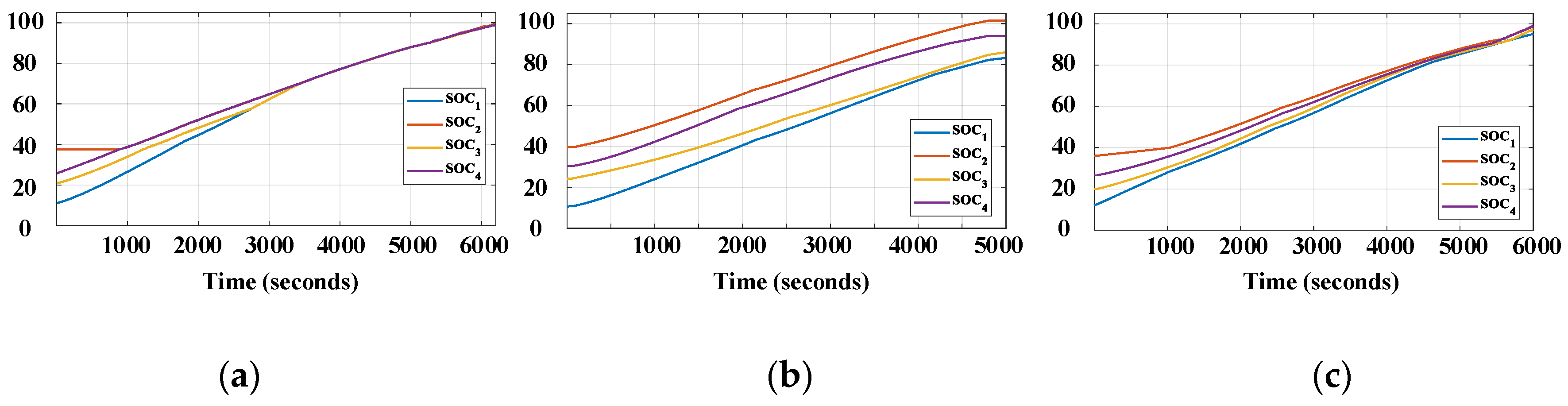
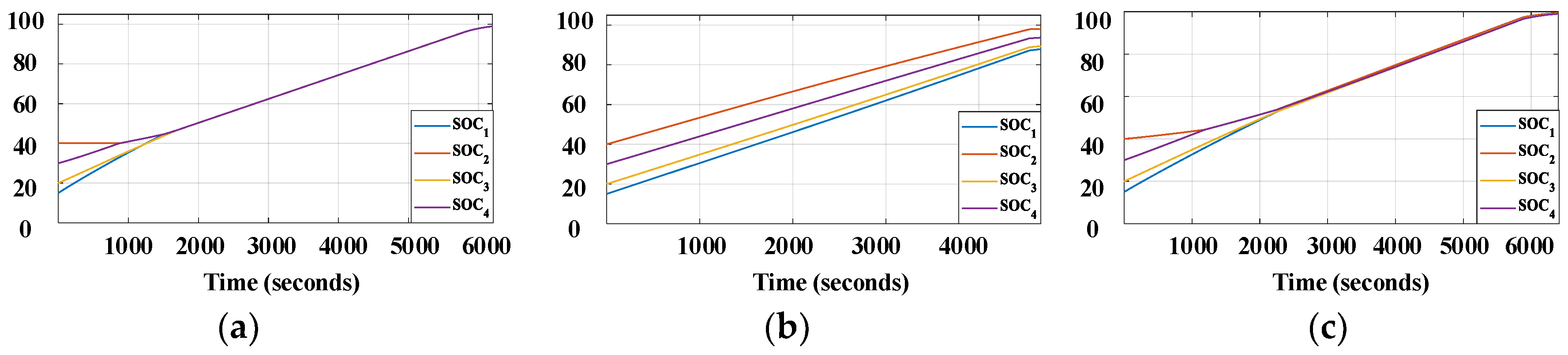
4.3. Equalization Performance of Different Methods in 2S4P Configuration

The experiments are performed on the cells with the parameter in Section 3.2. During both charging and discharging mode, the proposed method is compared with the conventional methods: SOC-based sequencing in Figure 1b and the fixed-resistor method in Figure 1c.
In charging mode, the battery system is charged by the 3 A/8.4 V CC-CV method and the initial SOC of the cells are SOCinit1,2,3,4 = 15, 40, 20, 30%. Similarly, the battery cells are discharged by a constant current of 4 A with different initial SOCs (SOCinit1,2,3,4 = 100, 80, 90, 70%) in discharging mode. The equalization resistor of the proposed method is chosen as scenario 3 in Table 2 after the design optimization process, while the equalization resistor of the fixed-resistor method is chosen as 1 Ω. The experiment is stopped when any battery branch reaches 100% of the SOC during charging mode, or less than 5% of SOC during discharging mode. The SOC and currents of the battery branch are shown in Figure 8 and Figure 9 for charging mode, and Figure 10 and Figure 11 for discharging mode, respectively. Finally, the equalization performance indices are calculated and compared in Table 3 based on the experimental results.
The SOC profiles in Figure 8 (charging mode) and Figure 10 (discharging mode) show that both the SOC-sequencing and the proposed method have the almost equivalent SOC equalization performance: although the equalization speed of the SOC-sequencing method is higher than that of the proposed method, the DoSE indices of both are similar. It means that all branches can be almost fully charged or fully discharged. On the contrary, the DoSE index of the fixed-resistor method is low and the operation process is forced to stop before all cells are fully charged or discharged (Figure 8b and Figure 10b).
According to the current profiles in Figure 9b and Figure 11b, the conventional fixed-resistor method maintains the continuous current during both charging and discharging mode. On the contrary, the SOC-sequencing method creates the pulsating branch current waveform as in Figure 9a and Figure 11a, due to the control algorithm. As a result, the current increases the internal power loss of the battery cell, which is regarded as harmful to battery lifetime [29,30].
With the optimal design, the proposed method appropriately reduces the pulsation of the current during both the charging and discharging modes, as in Figure 9c and Figure 11c. As a result, the RMS currents of battery branches are also decreased, which reduces the internal power loss of battery. Further investigation on the impact of pulsating current is presented in Section 4.4. Additionally, three switching patterns can be identified in Figure 11c according to the operating analysis in Section 3.1. During pattern A, battery cell #4 is discharged with the lowest current until its SOC is equalized with cell #2. During pattern B, the algorithm alternatingly turns the switches in branches #2, #3, and #4 off and on to maintain the SOC equalization until the SOCs of all cells are equalized. After equalization is achieved within a certain level, the pattern C starts to turn all the switches on so that the load demand is distributed almost evenly between branches. After the SOCs become mismatch again, patterns A and B are repeated to recover the equalization status.

4.4. Efficiency Assessment of Different Methods in Various Configuration

In order to assess the efficiency of the proposed method in a real application where the series connection in parallel branches becomes large, the hardware in the loop (HIL) simulation of the proposed and conventional methods are implemented into 2S4P, 4S4P, and 8S4P battery configurations. The initial status of the battery branches and experiment setups are similar to Section 4.3. In order to check the feasibility of the HIL test, the 2S4P battery configuration is tested firstly and compared with the real hardware experimental results. The SOC and current profiles of the 2S4P battery configuration are illustrated in Figure 12 and Figure 13 for charging mode, and Figure 14 and Figure 15 for discharging mode, respectively. When compared with the experimental results in Section 4.3, the HIL simulation results are similar. Thus, the HIL simulation is reliable to assess the performance of balancing techniques in various battery configurations.
Power losses in the balancing systems can be decomposed into two different factors: the external power loss in the equalizer circuit and the internal power loss inside the battery. The external power losses of both the proposed and the SOC-sequencing method are calculated by (19) while it is calculated by (20) in the conventional fixed-resistor method, where Im_rms are the RMS current of the individual branch, R is the value of the equalization resistor.
P l o s s _ e x t e r n a l = m = 1 N I m _ r m s 2 R
Similarly, the total internal power loss of battery is calculated by (21), where Rb is the internal DC impedance of battery (70 mΩ) which is provided in the datasheet [28].
P l o s s _ i n t e r n a l = m = 1 N I m _ r m s 2 R b
The power losses of the equalizer are compared in Table 4. It shows that the internal loss is proportionally increased by the number of series connections, whereas external loss is almost unchanged. The internal loss of the SOC-sequencing method is always higher than the other by 20% in discharging mode and by 15% in charging mode. In other words, the SOC-sequencing method can reduce the lifetime of the battery system.
Because the number of series connections in the energy storage systems (BESS or EV) can be up to hundreds of cells, the curve fitting method is used to predict the power losses of proposed and conventional methods in larger battery configurations from the HIL simulation results. The power losses (external, internal, and total loss) based on HIL simulations and the predicted value are illustrated in the log–log curve in Figure 16. Although the external loss of the SOC-sequencing method is lower than the other methods, its total loss is dominated by the rapidly increasing internal loss. Therefore, when the number of series connections becomes larger, the proposed equalizer becomes more efficient than the SOC-sequencing method. When both total loss and equalization performance are considered together, the proposed equalizer becomes a promising method for parallel battery configuration with many series-connected cells.

5. Conclusions

This paper proposes a novel dynamic resistance equalizer for parallel-connected battery configurations. Based on the SOC status of battery cells, the switches are controlled to modulate the impedance of the parallel branches while adjusting the branch current. The experimental results show that the cell inconsistency issue in the parallel battery configuration is obviously mitigated, which helps make the parallel-connected battery safer with a prolonged lifetime. The power loss analysis based on HIL simulations also shows that the proposed method is effective, especially for a parallel battery system with many series-connected cells in view of both equalization performance and power loss. Therefore, the proposed method is expected to be suitable for applications such as EV or SL-BESS.

Author Contributions

Conceptualization, P.-H.L.; data curation, P.-H.L.; funding acquisition, S.-J.C.; investigation, P.-H.L.; methodology, P.-H.L. and S.-J.C.; project administration, S.-J.C.; resources, S.-J.C.; supervision, S.-J.C.; validation, P.-H.L.; visualization, S.-J.C.; writing—original draft, P.-H.L.; writing—review and editing, S.-J.C. All authors have read and agreed to the published version of the manuscript.

Funding

This work was supported by the 2017 Research Fund of University of Ulsan, Korea.

Conflicts of Interest

The authors declare no conflict of interest.

References

  1. European Commission. A Roadmap for Moving to a Competitive Low Carbon Economy in 2050; European Commission: Brussels, Belgium, 2011; Available online: https://eur-lex.europa.eu/legal-content/EN/ALL/?uri=CELEX%3A52011DC0112 (accessed on 28 June 2020).
  2. International Energy Agency (IEA), “Global EV Outlook”. 2019. Available online: https://webstore.iea.org/global-ev-outlook-2019 (accessed on 17 June 2019).
  3. Hunt, G. USABC Electric Vehicle Battery Test Procedures; United States Department of Energy: Washington, DC, USA, 1996.
  4. Weil, M.; Ziemann, S. Recycling of Traction Batteries as a Challenge and Chance for Future Lithium. In Lithium-Ion Batteries Advances and Applications; Pistoia, G., Ed.; Elsevier: Amsterdam, The Netherlands, 2014; pp. 509–528. [Google Scholar]
  5. Herrmann, C.; Raatz, A.; Andrew, S.; Schmitt, J. Scenario-Based of Disassembly Systems for Automotive Lithium-Ion Battery Systems. Adv. Mater. Res. 2014, 907, 391–401. [Google Scholar]
  6. Laserna, E.M.; Gandiaga, I.; Zabala, E.S.; Badeda, J.; Stroe, D.I.; Swierczynski, M.; Goikoetxea, A. Battery second life: Hype, hope, or reality? A critical review of the state of the art. Renew. Sustain. Energy Rev. 2018, 93, 701–718. [Google Scholar] [CrossRef]
  7. Qi, L.; Lu, D.D.C. Review of Battery Cell Balancing Techniques. In Proceedings of the Australasian Universities Power Engineering Conference, AUPEC 2014, Curtin University, Perth, Australia, 28 September–1 October 2014; pp. 1–6. [Google Scholar]
  8. Omariba, Z.B.; Zhang, L.J.; Sun, D.B. Review of Battery Cell Balancing Methodologies for Optimizing Battery Pack Performance in Electric Vehicles. IEEE Access 2019, 7, 129335–129352. [Google Scholar] [CrossRef]
  9. Li, H.; Peng, J.; He, J.P.; Huang, Z.W.; Pan, J.P.; Wang, J. Synchronized Cell-Balancing Charging of Supercapacitors: A Consensus-Based Approach. IEEE Trans. Ind. Electron. 2018, 65, 8030–8040. [Google Scholar] [CrossRef]
  10. Lim, C.-S.; Lee, K.-J.; Ku, N.-J.; Hyun, D.-S.; Kim, R.-Y. A modularized equalization method based on magnetizing energy for a series-connected Lithium-ion battery string. IEEE Trans. Power Electron. 2014, 29, 1791–1799. [Google Scholar] [CrossRef]
  11. Shang, Y.L.; Cui, N.; Duan, B.; Zhang, C. Analysis and Optimization of Star-Structured Switched-Capacitor Equalizer for Series-Connected Battery Strings. IEEE Trans. Power Electron. 2018, 33, 9631–9646. [Google Scholar] [CrossRef]
  12. Yarlagadda, S.; Hartley, T.T.; Husain, I. A Battery Management System Using an Active Charge Equalization Technique Based on a DC/DC Converter Topology. IEEE Trans. Ind. Appl. 2013, 49, 2720–2729. [Google Scholar] [CrossRef]
  13. U.S. Department of Energy; Idaho National Laboratory. 2011 Nissan Leaf—VIN 0356 Advanced Vehicle Testing—Beginning-of-Test Battery Testing Results. Available online: https://avt.inl.gov/sites/default/files/pdf/fsev/batteryrpt2011NissanLeaf0356.pdf (accessed on 28 June 2020).
  14. U.S. Department of Energy; Idaho National Laboratory. 2013 Chevrolet Volt Advanced Vehicle Testing—Beginning-of-Test Battery Testing Results. Available online: https://www.energy.gov/sites/prod/files/2014/02/f7/battery_volt_3929.pdf (accessed on 28 June 2020).
  15. Yang, N.; Zhang, X.; Shang, B.; Li, G. Unbalanced discharging and aging due to temperature differences among the cells in a lithium-ion battery pack with parallel combination. J. Power Sour. 2016, 306, 733–741. [Google Scholar] [CrossRef]
  16. Gong, X.; Xiong, R.; Mi, C.C. Study of the Characteristics of Battery Packs in Electric Vehicles with Parallel-Connected Lithium-ion Battery Cells. IEEE Trans. Ind. Appl. 2015, 51, 3218–3224. [Google Scholar] [CrossRef]
  17. Castano-Solis, S.; Serrano-Jimenez, D.; Gauchia, L.; Sanz, J. The Influence of BMSs on the Characterization and Modeling of Series and Parallel Li-ion Packs. Energies 2017, 10, 273. [Google Scholar] [CrossRef] [Green Version]
  18. Pastor-Fernandez, C.; Bruen, T.; Widanage, W.D.; Gama-Valdez, M.A.; Marco, J. A Study of Cell-to-Cell Interactions and Degradation in Parallel Strings: Implications for the Battery Management System. J. Power Sour. 2016, 329, 574–585. [Google Scholar] [CrossRef] [Green Version]
  19. Gogoana, R.; Pinson, M.B.; Bazant, M.Z.; Sarma, S.E. Internal Resistance Matching for Parallel-connected Lithium-ion Cells and Impacts on Battery Pack Cycle Life. J. Power Sour. 2014, 252, 8–13. [Google Scholar] [CrossRef]
  20. Guo, R.; Lu, L.; Ouyang, M.; Feng, X. Mechanism of the entire over-discharge process and over-discharge-induced internal short circuit in lithium-ion batteries. Sci. Rep. 2016, 6, 30248. [Google Scholar] [CrossRef] [PubMed] [Green Version]
  21. Ye, M.; Song, X.; Xiong, R.; Sun, F. A Novel Dynamic Performance Analysis and Evaluation Model of Series-Parallel Connected Battery Pack for Electric Vehicles. IEEE Access 2019, 7, 14256–14265. [Google Scholar] [CrossRef]
  22. Hahnsang, K.; Shin, K.G. DESA: Dependable, Efficient, Scalable Architecture for Management of Large-Scale Batteries. IEEE Trans. Ind. Inform. 2012, 8, 406–417. [Google Scholar]
  23. Kim, T.; Qiao, W.; Qu, L. Power Electronics-Enabled Self-X Multicell Batteries: A Design Toward Smart Batteries. IEEE Trans. Power Electron. 2012, 27, 4723–4733. [Google Scholar]
  24. Song, C.; Shao, Y.; Song, S.; Chang, C.; Zhou, F.; Peng, S.; Xiao, F. Energy Management of Parallel-Connected Cells in Electric Vehicles Based on Fuzzy Logic Control. Energies 2017, 10, 404. [Google Scholar] [CrossRef]
  25. Kuo, K.C.; Hsiao, S.H. Battery Balancing Circuit and Balancing Method Thereof and Battery Activation Method. U.S. Patent 8,643,334, 18 October 2012. [Google Scholar]
  26. La, P.H.; Tin, T.C.; Choi, S.J. Dynamic Resistance Battery Equalization for Capacity Optimization of Parallel-Connected Cells. In Proceedings of the IEEE 10th International Conference on Power Electronic—ECCE Asia, Busan, Korea, 27–30 May 2019. [Google Scholar]
  27. Meng, J.; Ricco, M.; Luo, G.; Swierczynski, M.; Stroe, D.I.; Stroe, A.I.; Teodorescu, R. An Overview and Comparison of Online Implementable SOC Estimation Methods for Lithium-ion Battery. IEEE Trans. Ind. Appl. 2018, 54, 1583–1591. [Google Scholar] [CrossRef]
  28. LG Chemical. LG 18650HD2 2000mAh Datasheet. Available online: https://voltaplex.com/media/whitepapers/specification-sheet/LG_HD2_Specification_Sheet.pdf (accessed on 28 June 2020).
  29. Choi, S.S.; Lim, H.S. Factors that Affect Cycle-life and Possible Degradation Mechanisms of a Li-ion Cell Based on LiCoO2. J. Power Sour. 2012, 111, 130–136. [Google Scholar] [CrossRef]
  30. Savoye, F.; Venet, P.; Millet, M.; Groot, J. Impact of periodic current pulses on Li-ion battery performance. IEEE Trans. Ind. Electron. 2012, 59, 3481–3488. [Google Scholar] [CrossRef]
Figure 1. Conventional methods: (a) directly-connected; (b) state-of-charge (SOC)-based sequencing method; (c) fixed-resistor method.
Energies 13 03315 g001
Figure 2. Proposed method: (a) dynamic resistance equalizer topology; (b) flowchart of the equalization.
Energies 13 03315 g002
Figure 3. Operation of dynamic resistance equalizer (DRE): (a) discharging process of four parallel-connected battery cells; (b) modeling of the dynamic resistance equalizer.
Energies 13 03315 g003
Figure 4. Typical switching patterns and corresponding branch currents.
Energies 13 03315 g004
Figure 5. Design plots for the balancing resistors: (a) maximum initial current difference vs. R2; (b) overall DoSE vs. R1.
Energies 13 03315 g005
Figure 6. Performance indices according to design scenario: (a) total power loss vs. R1 and R2; (b) required equalization time vs. R1 and R2.
Energies 13 03315 g006
Figure 7. Discharging mode–SOC of branches: (a) design scenario 1 (R1 = 0.1 Ω, R2 = 0.33 Ω); (b) design scenario 2 (R1 = 0.1 Ω, R2 = 1 Ω); (c) design scenario 3 (R1 = 0.1 Ω, R2 = 0.5 Ω).
Energies 13 03315 g007
Figure 8. Experimental results of charging mode for 2S4P configuration–SOC of branches: (a) SOC-based sequencing method; (b) fixed-resistor method; (c) proposed method.
Energies 13 03315 g008
Figure 9. Experimental result of charging mode for 2S4P configuration–branch currents: (a) SOC-based sequencing method; (b) fixed-resistor method; (c) proposed method.
Energies 13 03315 g009
Figure 10. Experimental result of discharging mode for 2S4P configuration–SOC of branches: (a) SOC-based sequencing method; (b) fixed-resistor method; (c) proposed method.
Energies 13 03315 g010
Figure 11. Experimental result of discharging mode for 2S4P configuration–branch currents: (a) SOC-based sequencing method; (b) fixed-resistor method; (c) proposed method.
Energies 13 03315 g011
Figure 12. Hardware in the loop (HIL) simulation of charging mode for 2S4P configuration–SOC of branches: (a) SOC-based sequencing method; (b) fixed-resistor method; (c) proposed method.
Energies 13 03315 g012
Figure 13. HIL simulation of charging mode for 2S4P configuration–branch currents: (a) SOC-based sequencing method; (b) fixed-resistor method; (c) proposed method.
Energies 13 03315 g013
Figure 14. HIL simulation of discharging mode for 2S4P configuration–SOC of branches: (a) SOC-based sequencing method; (b) fixed-resistor method; (c) proposed method.
Energies 13 03315 g014
Figure 15. HIL simulation of discharging mode for 2S4P configuration–branch currents: (a) SOC-based sequencing method; (b) fixed-resistor method; (c) proposed method.
Energies 13 03315 g015
Figure 16. Predicted power loss in: (a) charging mode—external loss; (b) discharging mode—external loss; (c) charging mode—internal loss; (d) discharging mode—internal loss; (e) charging mode—total loss; (f) discharging mode—total loss.
Energies 13 03315 g016
Table 1. Component list.
ComponentPart NumberQuantity
SwitchesIRF8313PbF4
Gate driverTC44294
Opto-coupler4N254
Fuel gaugeMAX17205G4
Table 2. Design scenario and performance comparisons.
Scenario 1Scenario 2Scenario 3
ΔSOCinitial (%)303030
ΔSOCfinal (%)5<1<1
R1 & R2 (Ω)0.1 & 0.330.1 & 10.1 & 0.5
DoSE (%)83.3>98>98
t2 (s)N/A23002500
Ploss_external (W)1.573.591.96
Table 3. Equalization performances comparison.
ModePerformance IndexFixed-Resistor MethodProposed MethodSOC Sequencing Method
Charging modeDoSE (%)409898
t2 (seconds)N/A45003400
Discharging modeDoSE (%)469898
t2 (seconds)N/A25002000
Table 4. Power loss comparison.
ModePerformance IndexFixed-Resistor MethodProposed MethodSOC Sequencing Method
2S4P Configuration
ChargingPloss_external (W)2.221.330.29
Ploss_internal (W)0.310.310.66
Total Loss (W)2.531.640.95
DischargingPloss_external (W)4.042.60.62
Ploss_internal (W)0.570.611.26
Total Loss (W)4.613.211.86
4S4P Configuration
ChargingPloss_external (W)2.241.340.28
Ploss_internal (W)0.620.631.29
Total Loss (W)2.861.971.57
DischargingPloss_external (W)4.072.630.61
Ploss_internal (W)1.141.242.54
Total Loss (W)5.213.873.14
8S4P Configuration
ChargingPloss_external (W)2.211.370.28
Ploss_internal (W)1.241.302.6
Total Loss (W)3.452.672.89
DischargingPloss_external (W)4.142.560.64
Ploss_internal (W)2.322.415.13
Total Loss (W)6.464.975.77

