Analysis of Synchronization Stability for Multi VSCs Parallel-Connected to Weak Grids by Improved Net Damping Criterion

 ,
, 
Abstract
:1. Introduction
- (1)
- Building a reduced small-signal model suitable for synchronization stability analysis of multi-VSC systems. The used VSC module is much simpler than the detailed one in [3] for synchronization stability studies owing to the neglection of fast inner current controls, but more accurate compared to the models given in [9,14] for counting the interactions between PLL and outer power controls.
- (2)
- Comprehensively applying net damping criterion to investigate multi-VSC system’s synchronization stability. The used criterion is a combination of the classical criterion propose by Canay [20] and an alternative one in our recent work [24], where the later can serve as a complement to enlarge the application feasibility of the classical criterion. The effectiveness of this method is confirmed by eigenvalue analysis. Additionally, with this method, the impact of various system parameters, including different grid strengths, power outputs and bandwidths of controllers, on closed-loop system stability are quantitatively examined.
2. Review of the Net Damping Criterion
2.1. The Classical Net Damping Criterion
2.2. Limitations and the Complemental Criterion
- Step (1)
- Applying the classical criterion, if the judgment result is instability then the system should be unstable; otherwise, if stability is predicted, go to Step (2);
- Step (2)
- Checking the damping in the low frequencies close to zero, stability is guaranteed for positive damping, while negative damping indicates instability.
3. System Modeling
4. Net Damping Based Stability Analysis
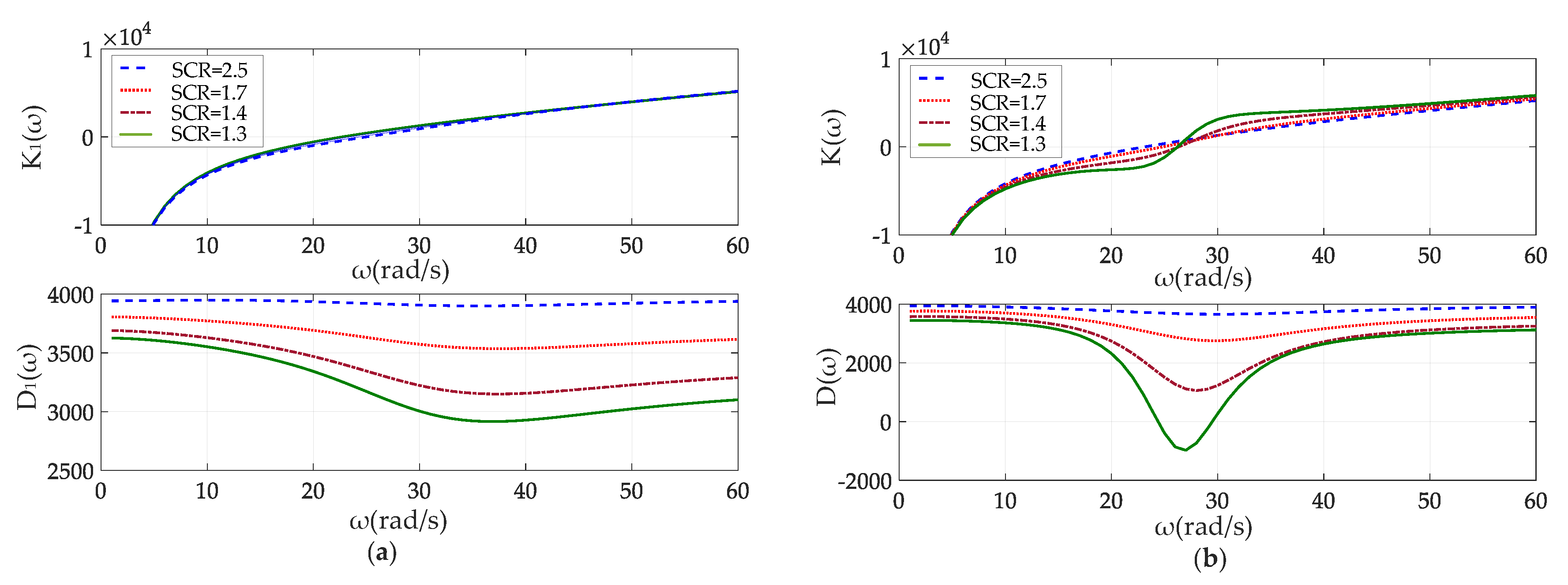
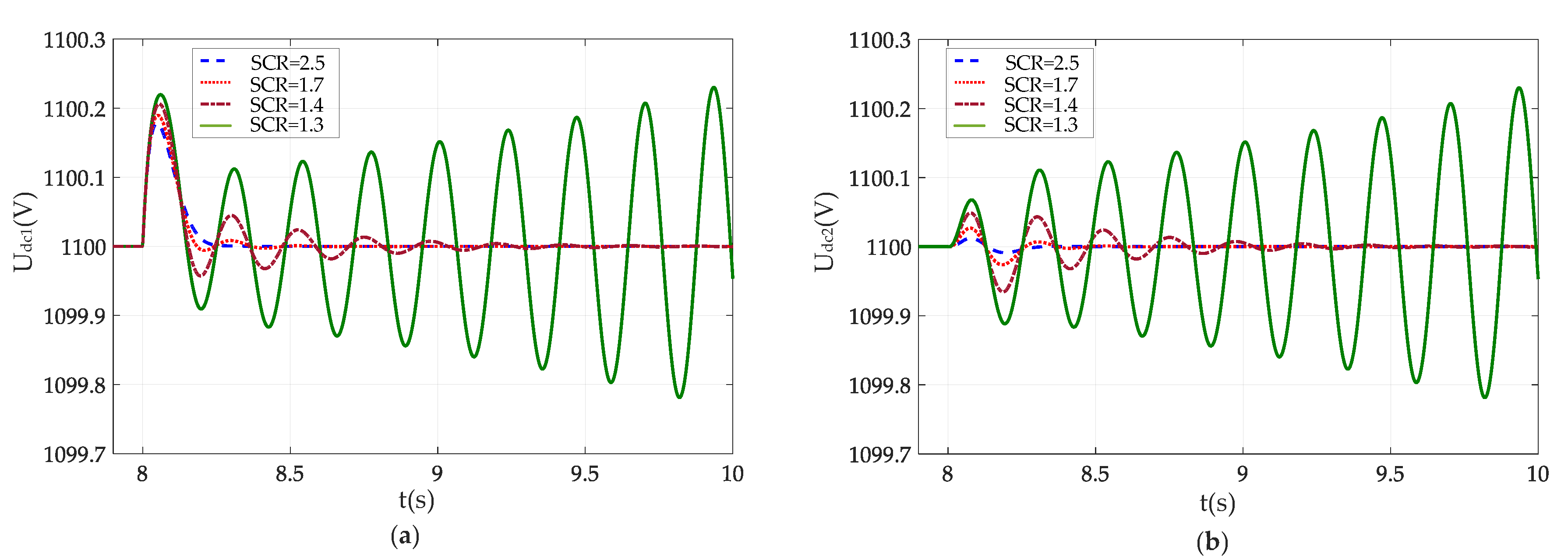
4.1. Effect of Grid Strength
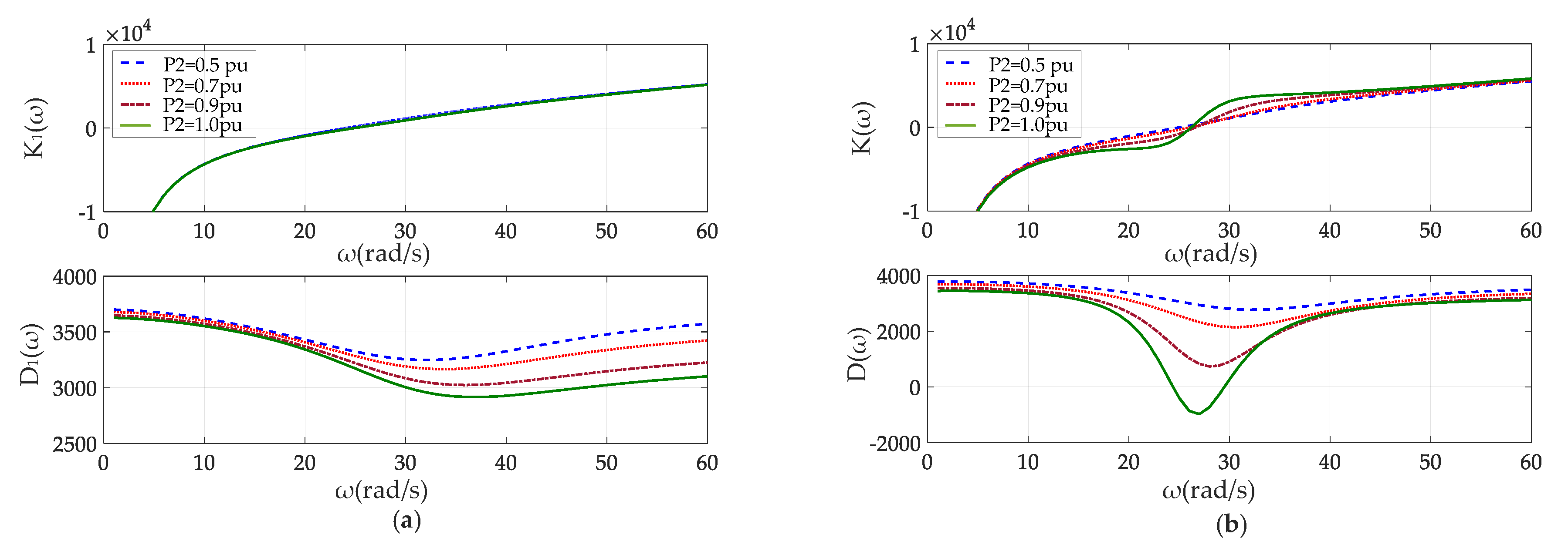
4.2. Effect of Loading Level
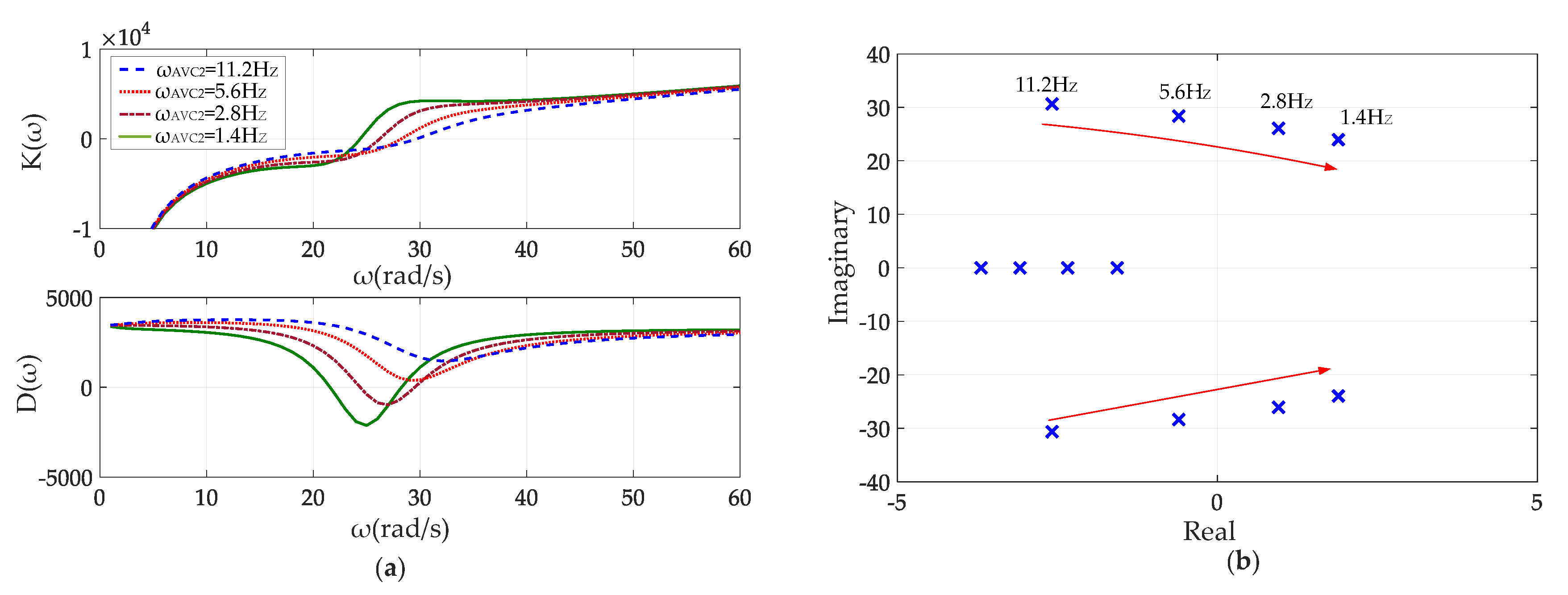
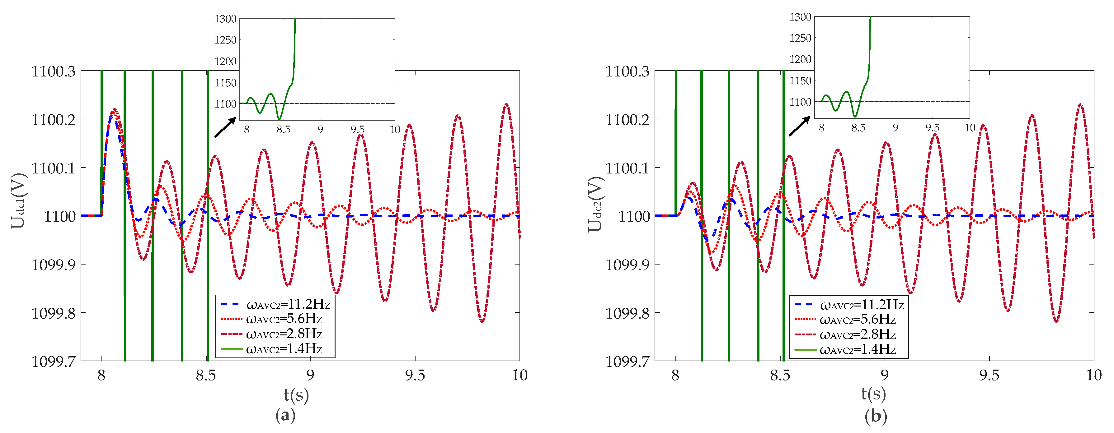
4.3. Effect of AC Voltage Control Tuning
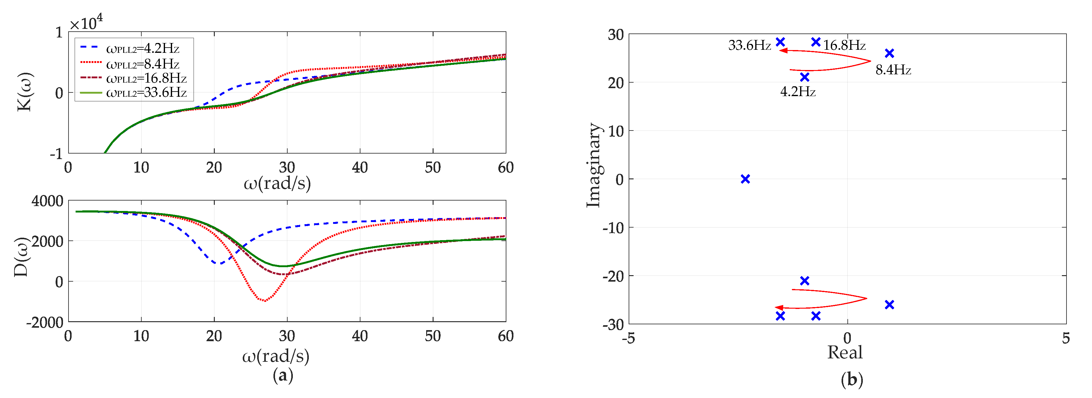
4.4. Effect of PLL Tuning
4.5. An Unusual Case
5. Simulation Studies
6. Conclusions
Author Contributions
Funding
Conflicts of Interest
Nomenclature
| Ut, θt | Terminal voltage magnitude and phase |
| θpll, ωpll | PLL output angle and frequency |
| Udc, C | DC-link voltage and capacitance |
| PCC | Point of common connection |
| X1, X2 | Reactance between terminal bus of VSC1 and VSC2 to the PCC |
| Xg | Reactance between PCC and the infinite bus |
| kp, ki | Proportion and integral control gain |
| Lg | Transmission line inductance between the PCC and the infinite bus |
| Li | Equivalent line inductance between VSC terminal bus and the PCC |
| Subscripts: | |
| 0 | Steady-state value |
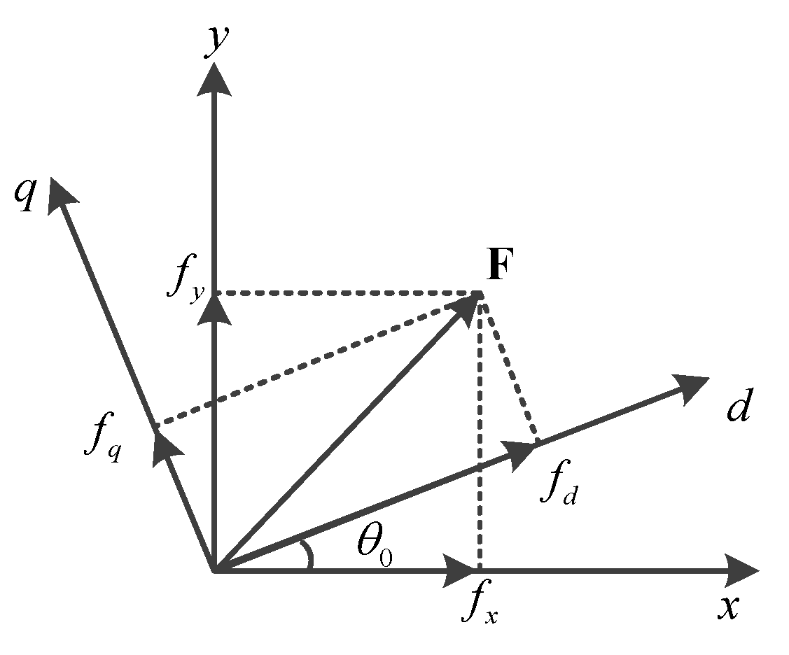
| d, q | Synchronous rotating reference frame signal d-axis and q-axis components |
| x, y | Global reference frame signal x-axis and y-axis components |
| ref | Reference signal |
| Superscript: | |
| p | Components in PLL rotating frame |
Appendix A
| Sbase = 1 MW | Ubase = 690 V(phase to phase RMS value) | ||
| ωbase = 2 πfbase | fbase = 50 Hz | Udcref = 1100 V | C = 0.09 F |
| Lf = 0.1 p.u. | L1 = 0.1 p.u. | L2 = 0.1 p.u. | |
| DC-link voltage control | kp1 = 5 | ki3 = 60 |
| AC voltage control | kp2 = 1 | ki2 = 100 |
| Phase-locked loop | kp3 = 40 | ki3 = 1400 |
| Current control | kp4 = 1 | ki4 = 50 |
References
- Teodorescu, R.; Liserre, M.; Rodriguez, P. Grid Converters for Photovoltaic and Wind Power Systems; Wiley IEEE Press: Piscataway, NJ, USA, 2011. [Google Scholar]
- Thacker, T.; Boroyevich, D.; Burgos, R.; Wang, F. Phase-locked loop noise reduction via phase detector implementation for single phase systems. IEEE Trans. Ind. Electron. 2011, 58, 2482–2490. [Google Scholar] [CrossRef]
- Zhang, H.; Harnefors, L.; Wang, X.; Gong, H.; Hasler, J.P. Stability Analysis of Grid-Connected Voltage-Source Converters Using SISO Modeling. IEEE Trans. Power Electron. 2019, 34, 8104–8117. [Google Scholar] [CrossRef]
- Li, S.; Yan, Y.; Yuan, X. SISO Equivalent of MIMO VSC-Dominated Power Systems for Voltage Amplitude and Phase Dynamic Analyses in Current Control Timescale. IEEE Trans. Energy Convers. 2019, 34, 1454–1465. [Google Scholar] [CrossRef]
- Yuan, H.; Yuan, X.; Hu, J. Modeling of grid-connected VSCs for power system small-signal stability analysis in DC-link voltage control timescale. IEEE Trans. Power Syst. 2017, 32, 3981–3991. [Google Scholar] [CrossRef]
- Huang, Y.; Zhai, X.; Hu, J.; Liu, D.; Lin, C. Modeling and Stability Analysis of VSC Internal Voltage in DC-Link Voltage Control Time Scale. IEEE J. Emerg. Sel. Top. Power Electron. 2018, 6, 16–28. [Google Scholar] [CrossRef]
- Zhou, J.; Ding, H.; Fan, S. Impact of short-circuit ratio and phase-locked-loop parameters on the small-signal behavior of a VSC-HVDC converter. IEEE Trans. Power Deliv. 2014, 29, 2287–2296. [Google Scholar] [CrossRef]
- Alawasa, K.M.; Mohamed, Y.A.; Xu, W. Active Mitigation of Subsynchronous Interactions Between PWM Voltage-Source Converters and Power Networks. IEEE Trans. Power Electron. 2014, 29, 121–134. [Google Scholar] [CrossRef]
- Wen, B.; Dong, D.; Boroyevich, D.; Burgos, R.; Mattavelli, P.; Shen, Z. Impedance-Based Analysis of Grid-Synchronization Stability for Three-Phase Paralleled Converters. IEEE Trans. Power Electron. 2016, 31, 26–38. [Google Scholar] [CrossRef]
- Li, C.; Burgos, R.; Wen, B.; Tang, Y.; Boroyevich, D. Stability Analysis of Power Systems with Multiple STATCOMs in Close Proximity. IEEE Trans. Power Electron. 2020, 35, 2268–2283. [Google Scholar] [CrossRef]
- Yuan, Z.; Du, Z.; Li, G. Analysis on the dynamic behaviours and interactions of VSC-MTDC grid. IET Gener. Transm. Distrib. 2018, 12, 1756–1764. [Google Scholar] [CrossRef]
- Zheng, W.; Hu, J.; Yuan, X. Modeling of VSCs Considering Input and Output Active Power Dynamics for Multi-Terminal HVDC Interaction Analysis in DC Voltage Control Timescale. IEEE Trans. Energy Convers. 2019, 34, 2008–2018. [Google Scholar] [CrossRef]
- Huang, Y.; Wang, D.; Shang, L.; Zhu, G.; Tang, H.; Li, Y. Modeling and stability analysis of DC-link voltage control in multi VSCs with integrated to weak grid. IEEE Trans. Energy Convers. 2017, 32, 1127–1138. [Google Scholar] [CrossRef]
- Rosso, R.; Andresen, M.; Engelken, S.; Liserre, M. Analysis of the interaction among power converters through their synchronization mechanism. IEEE Trans. Power Electron. 2019, 34, 12321–12332. [Google Scholar] [CrossRef]
- Wang, D.; Huang, Y.; Liao, M.; Zhu, G.; Deng, X. Grid-synchronization stability analysis for multi DFIGs connected in parallel to weak AC grids. Energies 2019, 12, 4361. [Google Scholar] [CrossRef] [Green Version]
- Turner, R.; Walton, S.; Duke, R. A case study on the application of the Nyquist stability criterion as applied to interconnected loads ans sources on grids. IEEE Trans. Ind. Electron. 2013, 60, 2740–2749. [Google Scholar] [CrossRef]
- Wang, X.; Blaabjerg, F.; Loh, P.C. Passivity-based stability analysis and damping injection for multi paralleled VSCs with LCL filters. IEEE Trans. Power Electron. 2017, 32, 8922–8935. [Google Scholar] [CrossRef] [Green Version]
- Harnefors, L.; Wang, X.; Yepes, A.G.; Blaabjerg, F. Passivity-based stability assessment of grid-connected VSCs—An overview. IEEE J. Emerg. Sel. Top. Power Electron. 2016, 4, 116–125. [Google Scholar] [CrossRef] [Green Version]
- Harnefors, L. Modeling of three-phase dynamic systems using complex transfer functions and transfer matrices. IEEE Trans. Ind. Electron. 2007, 54, 2239–2248. [Google Scholar] [CrossRef]
- Canay, I.M. A novel approach to the torsional interaction and electrical damping of synchronous machine, part I: Theory. IEEE Trans. Power App. Syst. 1982, PAS-101, 3630–3638. [Google Scholar] [CrossRef]
- Canay, I.M. A novel approach to the torsional interaction and electrical damping of synchronous machine, part II: Application to an arbitrary network. IEEE Trans. Power App. Syst. 1982, PAS-101, 3639–3647. [Google Scholar] [CrossRef]
- Stamatiou, G.; Bongiorno, M. Stability analysis of two-terminal VSC-HVDC systems using the net-damping criterion. IEEE Trans. Power Deliv. 2016, 31, 1748–1756. [Google Scholar] [CrossRef]
- Tabesh, A.; Iravani, R. On the application of the complex torque coefficients method to the analysis of torsional dynamics. IEEE Trans. Energy Convers. 2005, 20, 268–275. [Google Scholar] [CrossRef]
- Wang, D.; Hou, Y.; Hu, J. Net Damping Criterion for Stability Analysis of Grid-Tied VSCs in DC Voltage Control Timescale. CSEE J. Power Energy Syst. 2020. In early access. [Google Scholar] [CrossRef]
- Harnefors, L. Proof and application of the positive-net-damping stability criterion. IEEE Trans. Power Syst. 2011, 26, 481–482. [Google Scholar] [CrossRef]
- Sainz, L.; Cheah-Mane, M.; Monjo, L.; Liang, J.; Gomis-Bellmunt, O. Positive-net-damping stability criterion in grid-connected VSC systems. IEEE J. Emerg. Sel. Top. Power Electron. 2017, 5, 1499–1512. [Google Scholar] [CrossRef]
- Cheah-Mane, M.; Sainz, L.; Liang, J.; Jenkins, N.; Ugalde-Loo, C.E. Criterion for electrical resonance stability of offshore wind power plants connected through HVDC links. IEEE Trans. Power Syst. 2017, 32, 4579–4589. [Google Scholar] [CrossRef] [Green Version]
- Fan, L.; Miao, Z. An explanation of oscillations due to wind power plants weak grid interconnection. IEEE Trans. Sustain. Energy. 2018, 9, 488–490. [Google Scholar] [CrossRef]
- Wang, D.; Liang, L.; Hu, J.; Chang, N.; Hou, Y. Analysis of low-frequency stability in grid-tied DFIGs by nonminimum phase zero identification. IEEE Trans. Energy Convers. 2018, 33, 716–729. [Google Scholar] [CrossRef]
- Harnefors, L.; Bongiorno, M.; Lundberg, S. Input-admittance calculation and shaping for controlled voltage-source converters. IEEE Trans. Ind. Electron. 2007, 54, 3323–3334. [Google Scholar] [CrossRef]
- He, W.; Yuan, X.; Hu, J. Inertia provision and estimation of PLL-based DFIG wind turbines. IEEE Trans. Power Syst. 2017, 32, 510–521. [Google Scholar] [CrossRef]


© 2020 by the authors. Licensee MDPI, Basel, Switzerland. This article is an open access article distributed under the terms and conditions of the Creative Commons Attribution (CC BY) license (http://creativecommons.org/licenses/by/4.0/).
Share and Cite
Wang, D.; Zhang, X.; Yang, L.; Huang, Y.; Huang, W.; Wu, C.; Li, S. Analysis of Synchronization Stability for Multi VSCs Parallel-Connected to Weak Grids by Improved Net Damping Criterion. Energies 2020, 13, 3316. https://doi.org/10.3390/en13133316
Wang D, Zhang X, Yang L, Huang Y, Huang W, Wu C, Li S. Analysis of Synchronization Stability for Multi VSCs Parallel-Connected to Weak Grids by Improved Net Damping Criterion. Energies. 2020; 13(13):3316. https://doi.org/10.3390/en13133316
Chicago/Turabian StyleWang, Dong, Xiaojie Zhang, Lei Yang, Yunhui Huang, Wei Huang, Chen Wu, and Shengnan Li. 2020. "Analysis of Synchronization Stability for Multi VSCs Parallel-Connected to Weak Grids by Improved Net Damping Criterion" Energies 13, no. 13: 3316. https://doi.org/10.3390/en13133316
APA StyleWang, D., Zhang, X., Yang, L., Huang, Y., Huang, W., Wu, C., & Li, S. (2020). Analysis of Synchronization Stability for Multi VSCs Parallel-Connected to Weak Grids by Improved Net Damping Criterion. Energies, 13(13), 3316. https://doi.org/10.3390/en13133316