Article

Development of Enhancing Battery Management for Reusing Automotive Lithium-Ion Battery

1
Wistron Corporation, Hsichih 22181, Taiwan
2
Department of Naval Architecture and Ocean Engineering, Chosun university, Gwangju 61452, Korea
3
Center for Environmental Risk Management, Chung Yuan Christian University, ChungLi 32023, Taiwan
4
Vigourpack Co., Ltd., Taichung 408, Taiwan
*
Author to whom correspondence should be addressed.
Energies 2020, 13(13), 3306; https://doi.org/10.3390/en13133306
Submission received: 29 May 2020 / Revised: 21 June 2020 / Accepted: 23 June 2020 / Published: 28 June 2020
(This article belongs to the Special Issue Electric Systems for Transportation)

Abstract

:
In this study, a battery management system (BMS) is developed for reused lithium-ion battery (RLIB). Additional enhancing functions of battery management are established, i.e., estimation of life-sensitized parameters and life extension. Life-sensitizing parameters mainly include open-circuit voltage (OCV) and internal resistances (IRs). They are sensitized parameters individually relative to state of charge (SOC) and state of health (SOH). For estimating these two parameters, an adaptive control scheme is implemented in BMS. This online adaptive control approach has been extensively applied to nonlinear systems with uncertainties. In two experiments, OCV and IRs of reused battery packs are accurately extracted from working voltage and discharge current. An offline numerical model using a schematic method is applied to verify the applicability and efficiency of this proposed online scheme. Furthermore, a solution of actively extending life by using an ultracapacitor to share peak power of RLIB through adjusting duty ratio is also proposed. It is shown that this enhancing battery management for RLIB can properly estimate OCV and IRs, and actively extend the life of the RLIB in two experiments.

1. Introduction

Well-known greenhouse gas (GHG) emissions, due to extensive use of diesel and gasoline, threaten our environment [1]. A large amount of CO2 from transportation is gradually decreasing [2,3]. Meanwhile, electric vehicles (EVs) have been identified as being a key technology in reducing emissions and energy consumption in the transport sector [4]. Most countries are stepping up the introduction of electric vehicles, and are trying to progressively replace traditional fuel vehicles with EVs. However, with the rapidly increasing popularity of various EVs, the demand for lithium-ion batteries (LIBs) increases annually [5,6]. Sales of pure electric cars rose by nearly 14% in 2018 compared to 2017, while hybrid and plug-in hybrid sales rose by more than 20%. Now, more than 1.15 million EVs are on the roads today in the world [7]. Consequently, the quantity of wasted LIBs is also quickly increasing [8]. However, wasted battery packs are still available for energy balancing in thermal power plants, due to their residual electrical capacity [9]. Reuse of LIBs has become crucial in recent years [10], since renewable energy sources such as solar energy and wind energy are intermittent in nature. They have to keep continuous and reliable supply [11,12,13]. One of the best ways of stabling these renewable resources is to be stored in batteries. Among them, LIB is widely accepted due to its high energy density, long lifespan, and high efficiency [8,14,15]. However, the lifecycles of reused LIBs (RLIBs) become short, because the geometrical structure of the battery is possibly damaged by cycling use [16]. Therefore, an effective battery management system (BMS) for RLIB is compulsory, so that batteries can operate safely and reliably, preventing any physical damages and cell unbalancing [17]. Besides this, the state of charge (SOC) in BMS is considered as one of the critical and important basic parameters [14,18,19,20], which indicates how much remaining capacity is left inside a battery. Accurate estimation of SOC not only helps to provide information about the charge current and remaining performance of the battery, but also gives assurance of reliable and safe operation of the battery. However, the performance of the battery is highly affected by aging, temperature variation, and charge/discharge cycles, which make the task of estimating accurate SOC very challenging [21]. Therefore, we apply an adaptive control algorithm [16] for online estimation of key parameters, which are known as simple and easy to implement in BMS. For reused batteries, online estimations of electrochemical related parameters, such as internal resistances, are capable of real-time monitoring of the safety of reused batteries, rather than normal battery management systems for new batteries. Besides this, for prolonging a RLIB’s life, one ultracapacitor (UC) is connected and controlled by BMS to share peak load power. One simple pulse-width modulation (PWM) module is adopted to adjust the duty ratio of RLIB. Verification of this battery management for RLIB is conducted by systematic testing on bench by monitoring online results of estimation. It is expected that this study will contribute to promoting the systematic reuse of wasted LIB in industry before the chemical method.

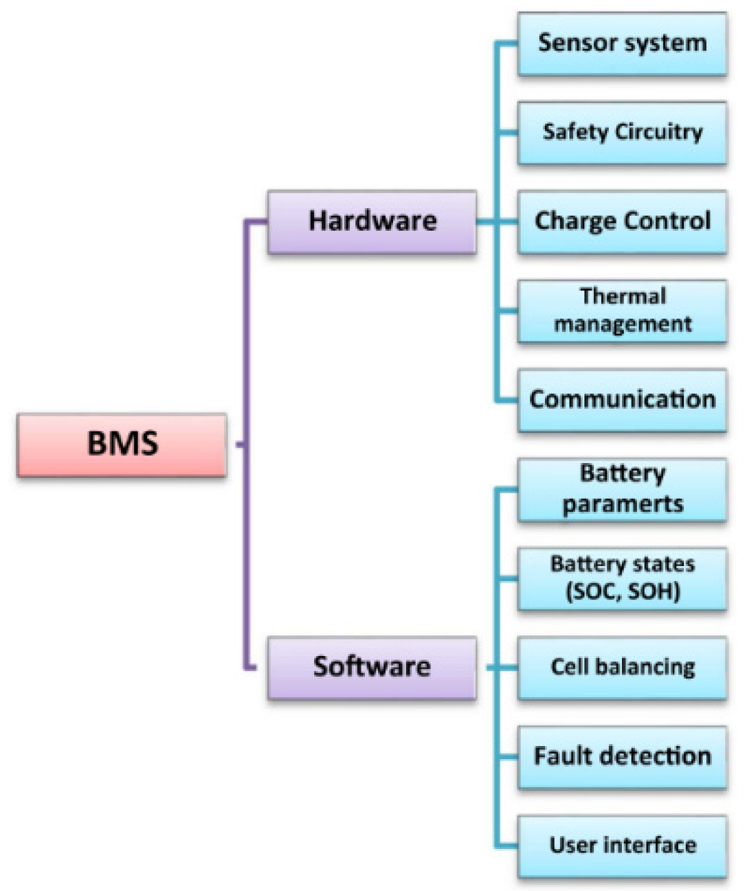
2. Enhancing Battery Management of Extending Life for RLIB

Generally, the states of LIB monitored by battery management systems include working temperature, voltage and current, and safety functions to avoid any overcharge/over-discharge. Relative functions of BMS can be categorized into hardware side and software side, as shown in Figure 1. In the hardware side, in case of centralized circuit BMS, cell voltage and temperature are measured by sensors in the external board, MMU (module monitoring unit), as shown in Figure 2a,b. Total data from the slave MMU are collected in the master BCU (battery control unit) for estimating SOC and SOH (state of health) through SPI (serial peripheral interface) protocol, as shown in Figure 2a. The analog-to-digital converter (ADC) measures the working current of the battery. This work is implemented based on Renesas Electronics Corporation ISL78600, as shown in Figure 2b. ISL78600 IC supervises up to 12 series-connected cells in the MMU. For keeping the high-voltage safety of RLIB, one insulation-resistance-measure device is attached on the BCU, as shown in Figure 2a. Besides this, controller area network (CAN) and universal asynchronous receiver transmitter (UART) protocols are also adopted. Through these functions of communication, the online real-time states of the battery, such as working current, SOC, SOH, and temperature, are gathered and transferred to the display or upper-level controller. In the software side, an algorithm embedded in the BCU is developed for estimating SOC and SOH by using basic battery parameters. Cell balancing is conducted in the MMU. A real-time simulator is supported to achieve automatic data acquisition and processing, to further verify the algorithm [22].
In this study, additional enhancing battery management is studied in reusing a large-scale automotive LIB. Functions of life estimation and life extension are highlighted for an RLIB. The schematic hardware of life extension is listed in Figure 2a. One proper ultracapacitor (UC) is parallelly connected with the BMS under the PWM (pulse-width modulation) control, which is used to switch the duty ratio of the IGBT (insulated gate bipolar transistor) in unit time. The application of the ultracapacitor achieves sharing of the RLIB’s peak power so as to decrease the depth of discharge (DOD), and hence extends the lifecycle (i.e., SOH) of the RLIB. The duty ratio is a stationary value in every control case. A proper duty ratio can be estimated by calculating from the demand power, sustained time, and maximum power from the battery. The operation board of the BCU is shown in Figure 2c.

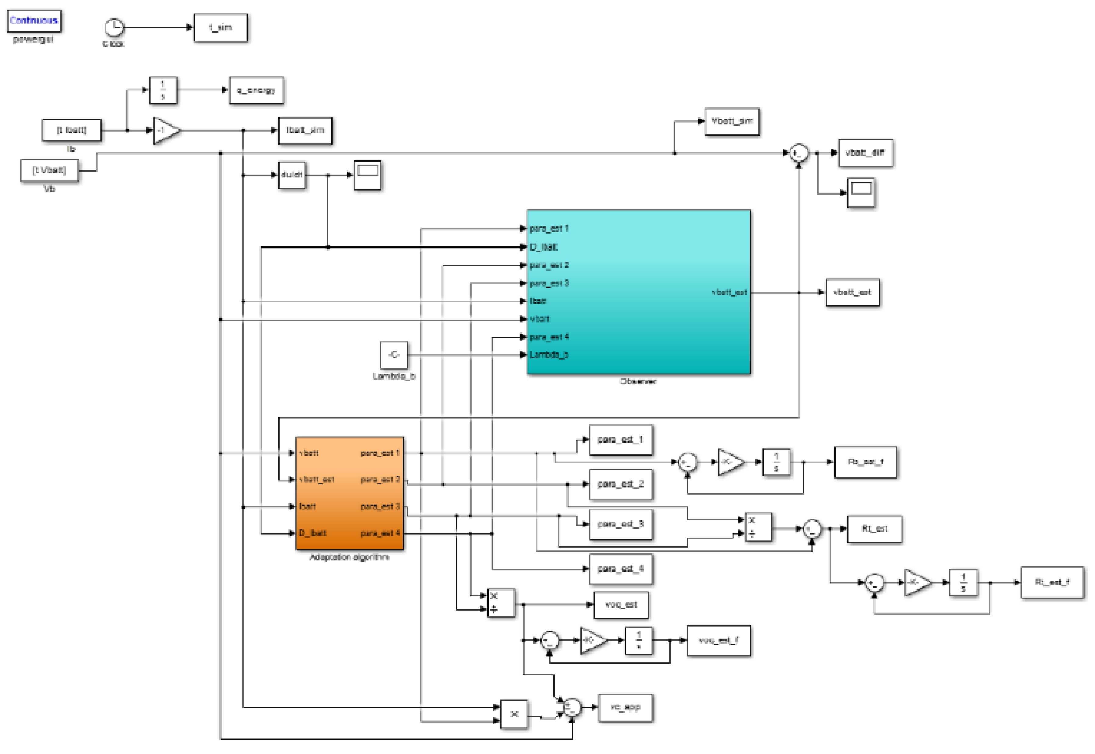
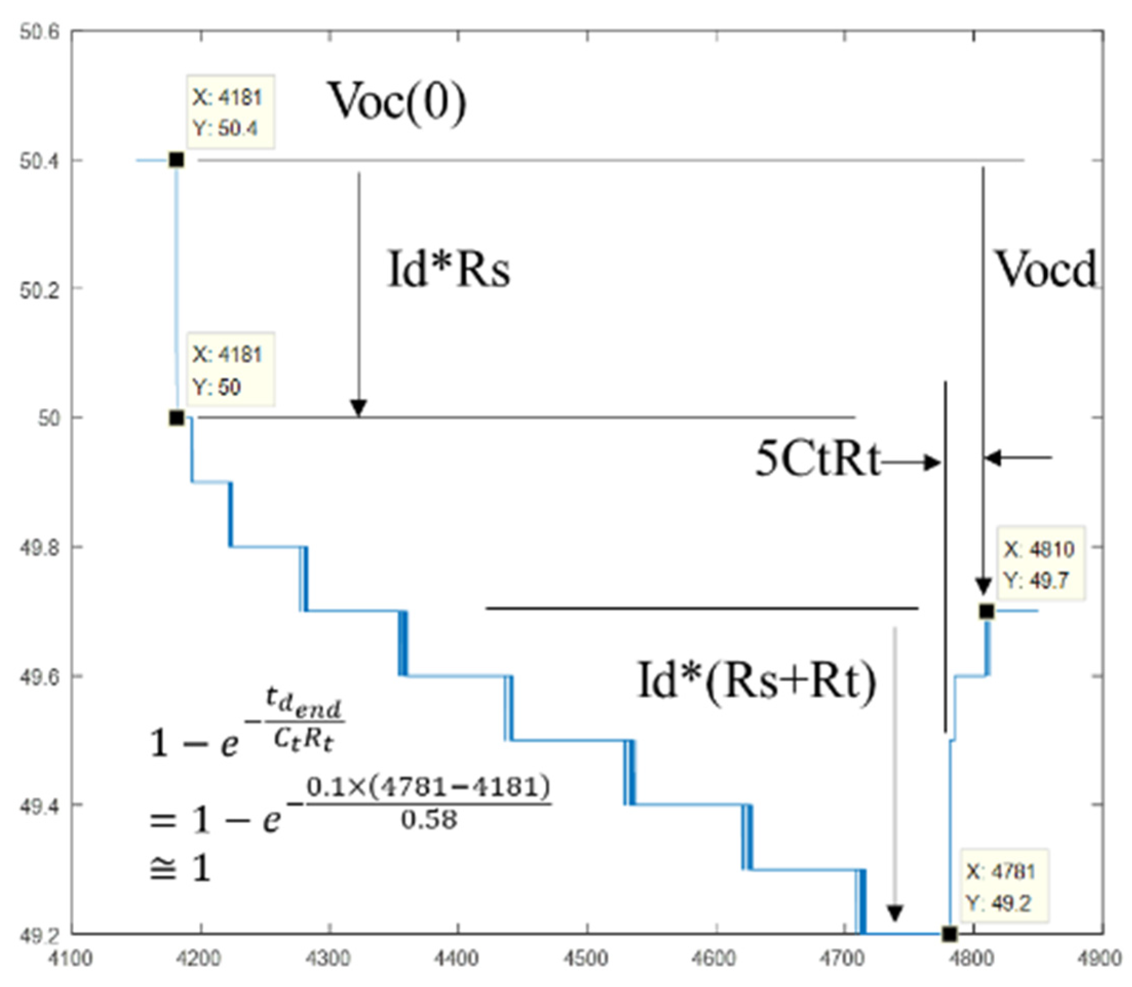
3. Adaptive Control Scheme for Estimating OCV and IRs

Online estimation of parameters open-circuit voltage (OCV) and internal resistances (IRs) of new battery is illustrated in [16]. These two parameters are relative to SOC and SOH [23,24]. The adaptive control algorithm guarantees estimating error converges to zero, by applying Lyapunov stability criteria. As a result, OCV and IRs can be precisely estimated from input parameters, i.e., working voltage and current. The detailed mathematical modeling in Simulink/MATLAB, according to an adaptive control scheme, is shown in Figure 3. The procedure is briefly summarized as below. First, the battery voltage can be expressed as:
v b ˙ = v ˙ o c R ˙ s i ˙ b ˙ R s i ˙ b ˙ v c ˙ = σ ( v o c ) x σ ( R S ) x i b R s i ˙ b ˙ v c ˙
Here,
σ ( p ) = [ p S o C   p T   p h ]
x T = [ S o C t   T t   h t ]
Here, v b , v o c , R S , R T , i ˙ b , and v c represent voltage of battery, open-circuit voltage, first-order and second-order IRs, battery current, and voltage drop across RC circuit, respectively, based on the electrical circuit model (ECM) shown in Figure 3. The projected parameters v b and R S are assumed as functions of SOC, T, and h, and change with time. In addition, Equation (1) can be simplified with the following assumptions:
(1) Small deviation of every battery’s discharge is assumed, compared to rated useful capacity, thus ∂SoC/∂t ≈ 0.
(2) In normal operating conditions, deviation of cell temperature, T is slow by using a fan, thus ∂T/∂t ≈ 0.
(3) A long-time usage history, h, is performed, thus ∂h/∂t ≈ 0.
Accordingly, it follows that Equation (3) ≈ 0; furthermore, Equation (1) can be rewritten as:
v b ˙ = ( v o c S o C S o C t + v o c T T t ) ( R S S o C S o C t + R S T T t ) i b 1 C t R t v b R s i b R t + R s C t R t i b + v o c C t R t  
Equation (4) can also be written as a vector form.
v b ˙ = θ T X
θ T = [ θ 1   θ 2   θ 3   θ 4 ] T = [ R s   R s + R t C t R t   1 C t R t   v o c C t R t ]
X T = [ i ˙ ˙ b i b v b   1 ]
Equation (6) is rewritten as Equation (8) with respect to every estimated state v ^ ˙ b
v b ^ ˙ = θ ^ T X ^ + u
where X ^ T = [ i ˙ ˙ b i b v ^ b   1 ] , u is adjustable for input parameters. θ is estimated results of target parameters.
The adaptive control algorithm is based on tracking input signals to modify the target parameters in control states, so that the convergent criteria are satisfied as below:
lim t e = lim t ( v b ( t ) v b ^ ( t ) ) = 0
Here, Rt and Ct represent first-order IR and capacitance, respectively, based on ECM. If the thermal effect of temperature is not considered, ∂T/∂t ≈ 0 is obtained.
The adaptive control algorithm shown in Figure 3 is introduced to optimize the unknown target parameters of Rs, Rt, and OCV in Equation (4). A filtering process is used to improve the measured noise and enhance the estimation reliability. In the estimation process, IR is a sensitized parameter of lifecycle, hence it is used to indicate the deviation of lifecycle. An OCV curve related to the battery’s useful capacity is applied to estimate the remained capacity of SOC. The algorithm is discretized, and embedded in BMS.

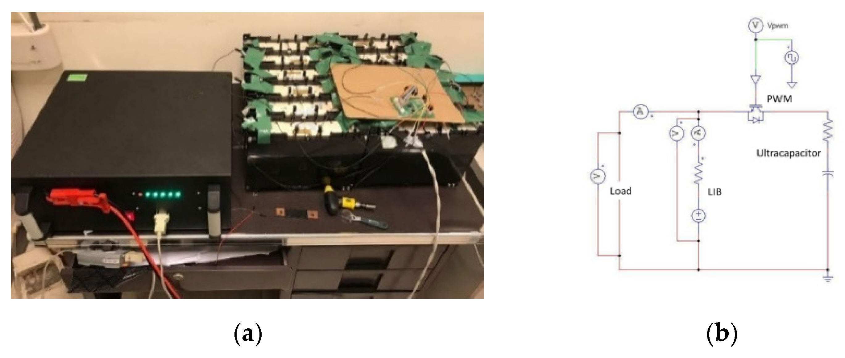
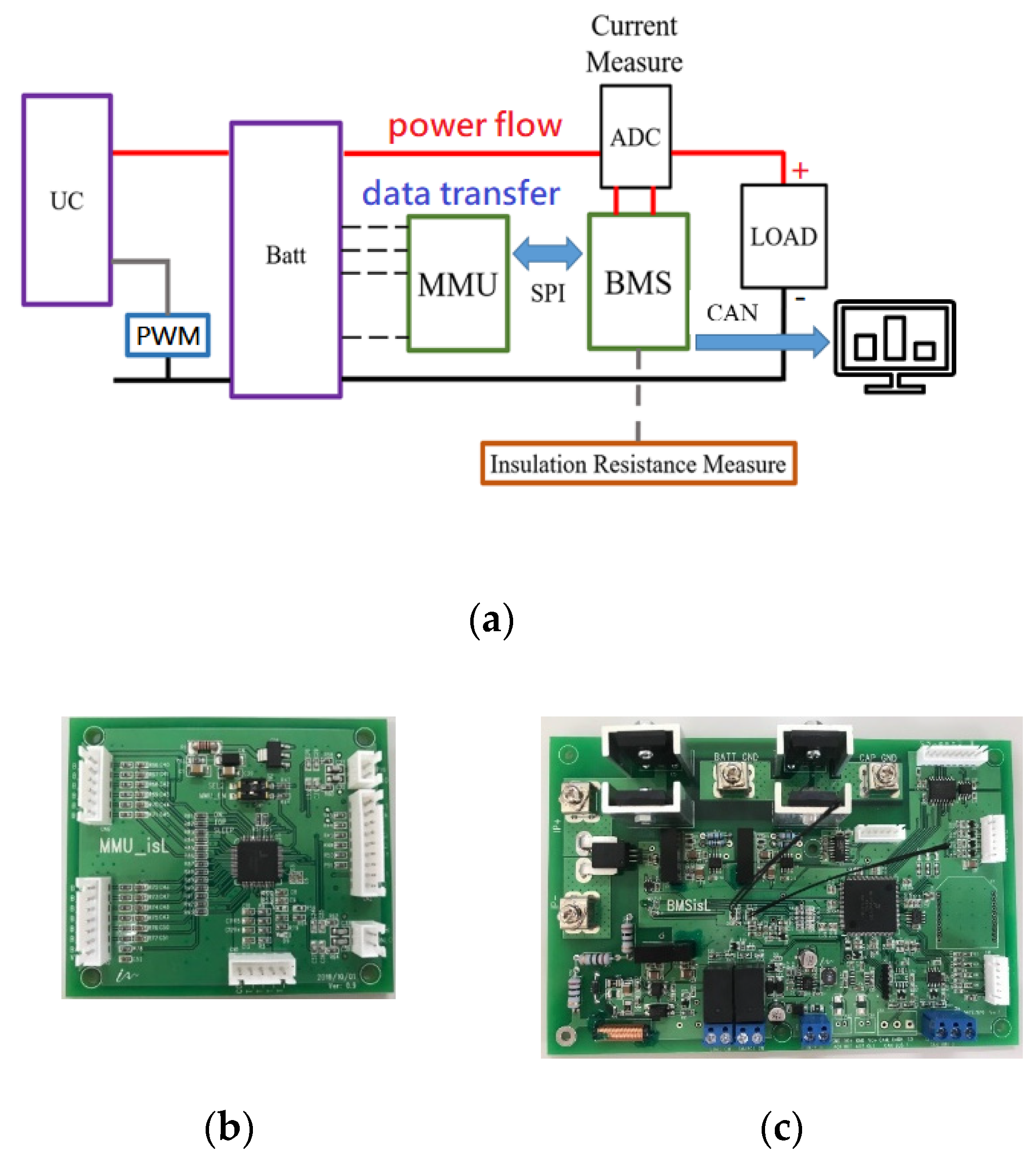
4. Setup of Test Bench
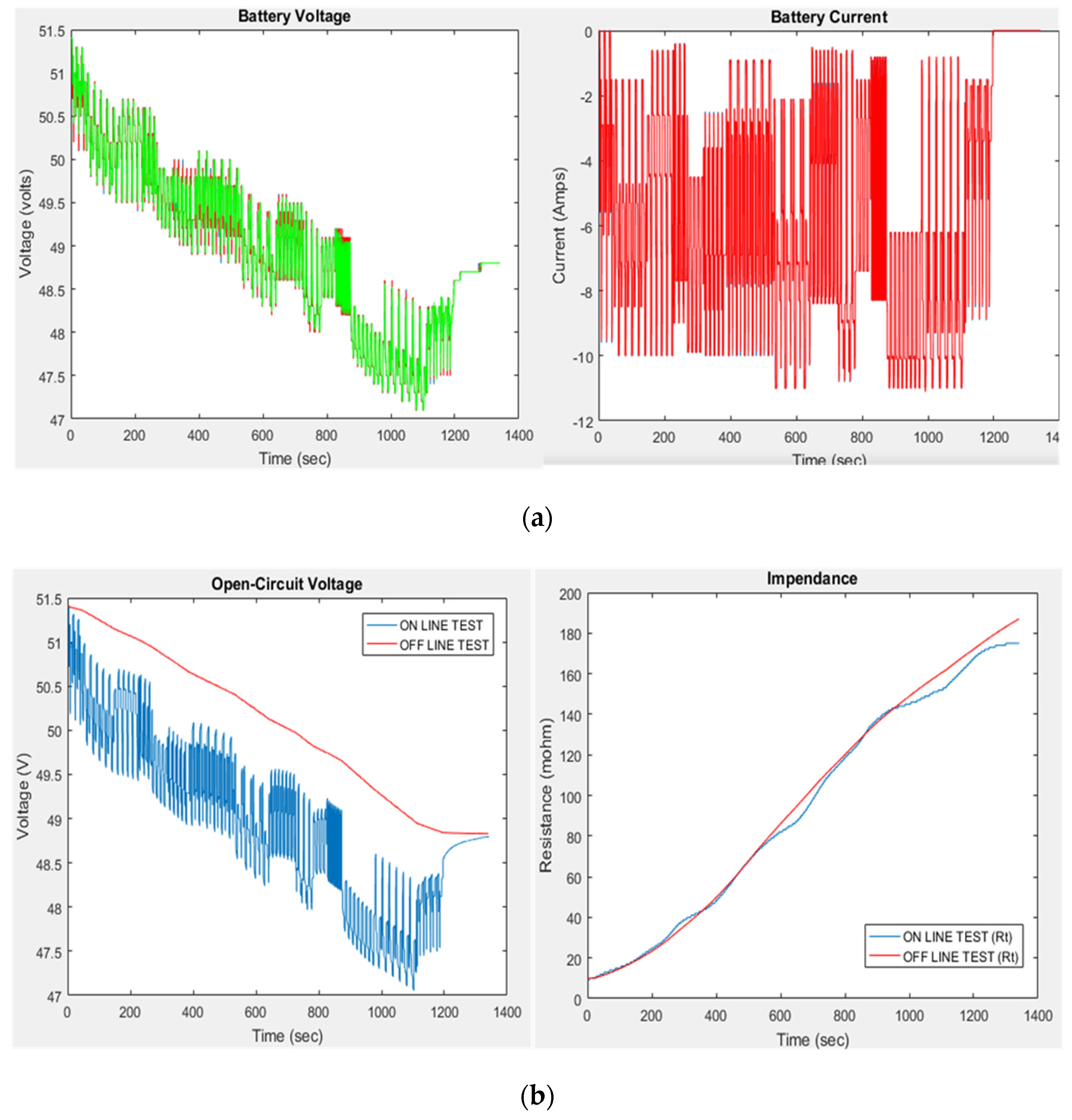
There are limitations of an electrochemical battery’s performance. The charge/discharge response of a lithium-ion battery is much slower than a UC. Therefore, for reusing a lithium-ion battery, a high-power UC can support sudden peak current, and extend the life of an LIB. To take a simple parallel combination between an RLIB and a UC, the ultracapacitor is operated as a dc-side buffer for supporting peak current. In case of using a DC-DC converter, it allows more flexible management between an RLIB and an ultracapacitor. However, it is not competitive in reusing cost. Consequently, a simple hybrid parallel connection is established in this study. PWM control is applied for adjusting the duty ratio of an RLIB. A UC connected with the BMS directly is to improve the life of the LIB, by restricting the voltage drop or DOD. RLIB packs with rated voltage of 52 V and 50.4 V are employed, respectively, as shown in Figure 4a. The first pack of 52 V uses a commercialized BMS for reference, and the other one of 50.4 V uses an in-house BMS. Figure 4b shows the developed circuit of the BMS with a PWM control in this study. If the duty ratio per unit time of battery is selected as 40%, then the UC’s load becomes 60%.

5. Results

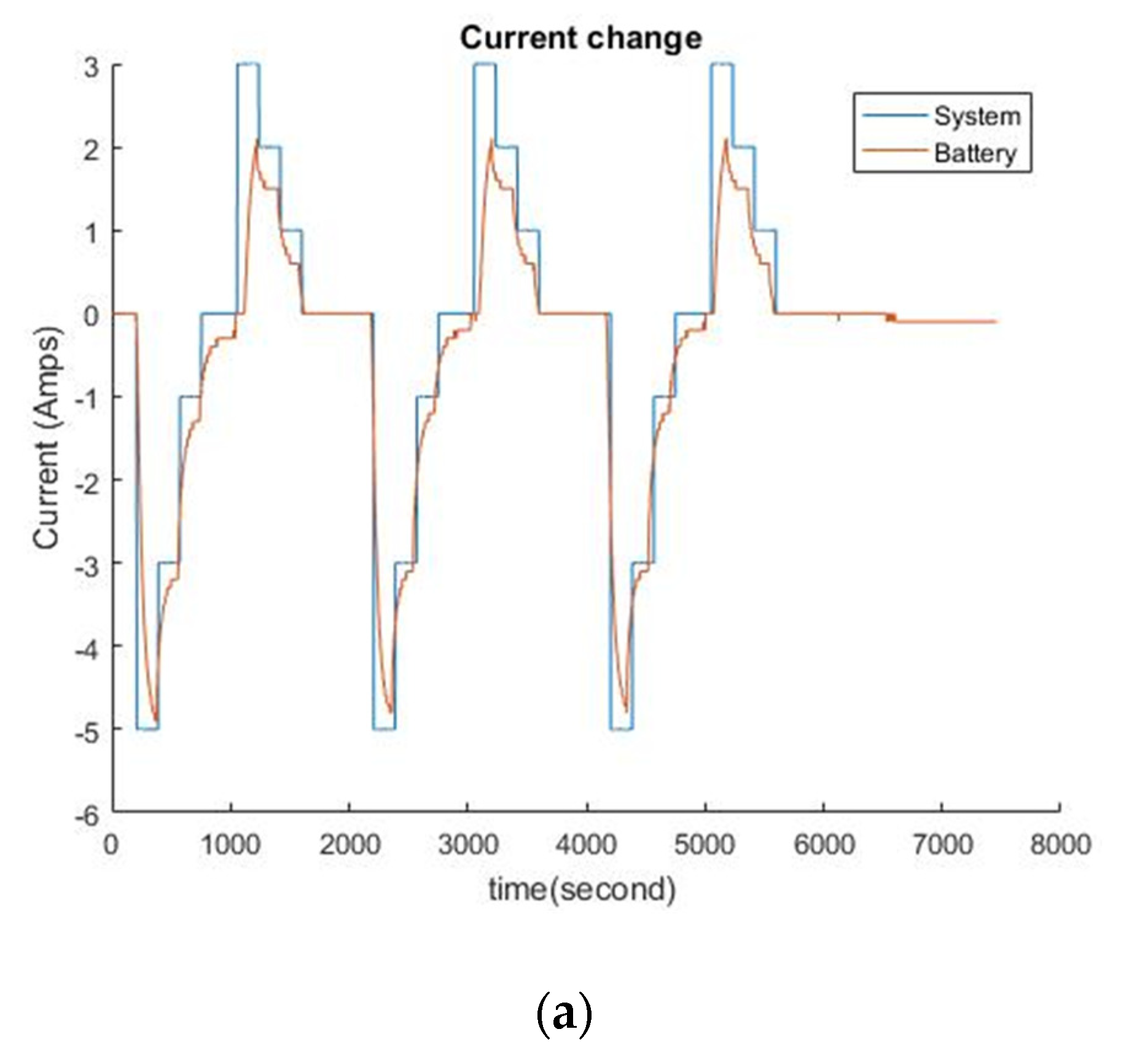
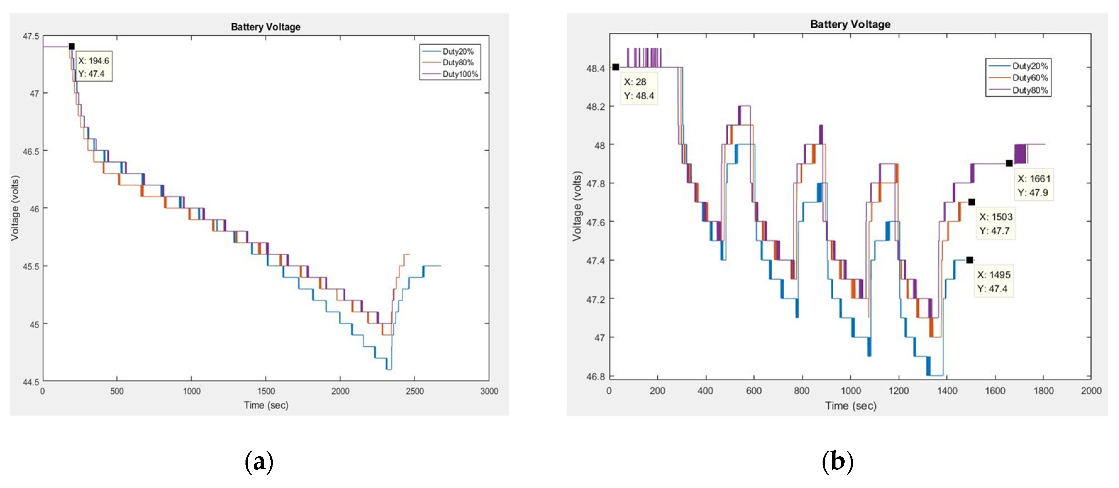
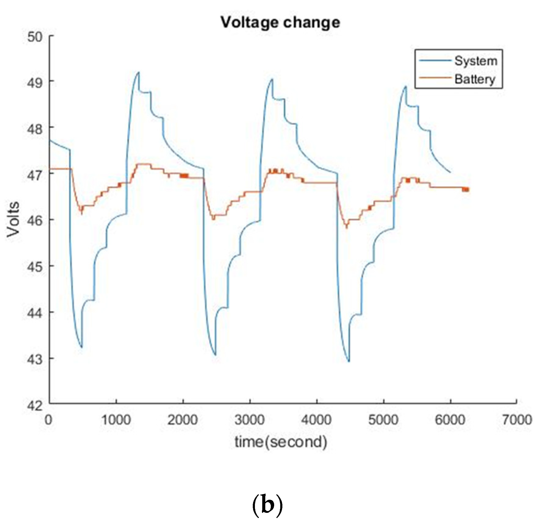
5.1. Life Extension Test by Using An Ultracapacitor

An ultracapacitor is a link between source and load. When used in parallel with the battery, it smooths out the load on the battery whilst improving the source impedance seen by the load. This may be viewed as the battery supplying the energy and the ultracapacitor supplying the short term power. Furthermore, to use an ultracapacitor matters in a battery’s life extension, due to the constrained voltage drop. Here, the duty ratio controls the loading between battery and ultracapacitor. Figure 5a,b shows voltage drop of 52 V/10 Ah battery pack, versus three duty ratios. For the first case, with a duty ratio of 20%, it presents the duty ratio of the battery’s loading as 80%, and on the contrary, the UC’s loading is 20%. In cases of duty ratios of 20%, 60%, and 80%, the terminal voltages were 47.4 V, 47.7 V, and 47.9 V, respectively. It shows the increased effect of constrained voltage drops of battery when increasing the duty ratio of ultracapacitor. Similar cases of 50 V battery pack were measured and are shown in Figure 6a,b. In Figure 6a,b, the blue line is the battery’s discharge, and the red line is the battery in parallel connection with UC, by setting to 75% duty ratio. The UC effectively reduces the voltage drop and decreases the DOD of the battery.

5.2. Estimation of OCV and IRs
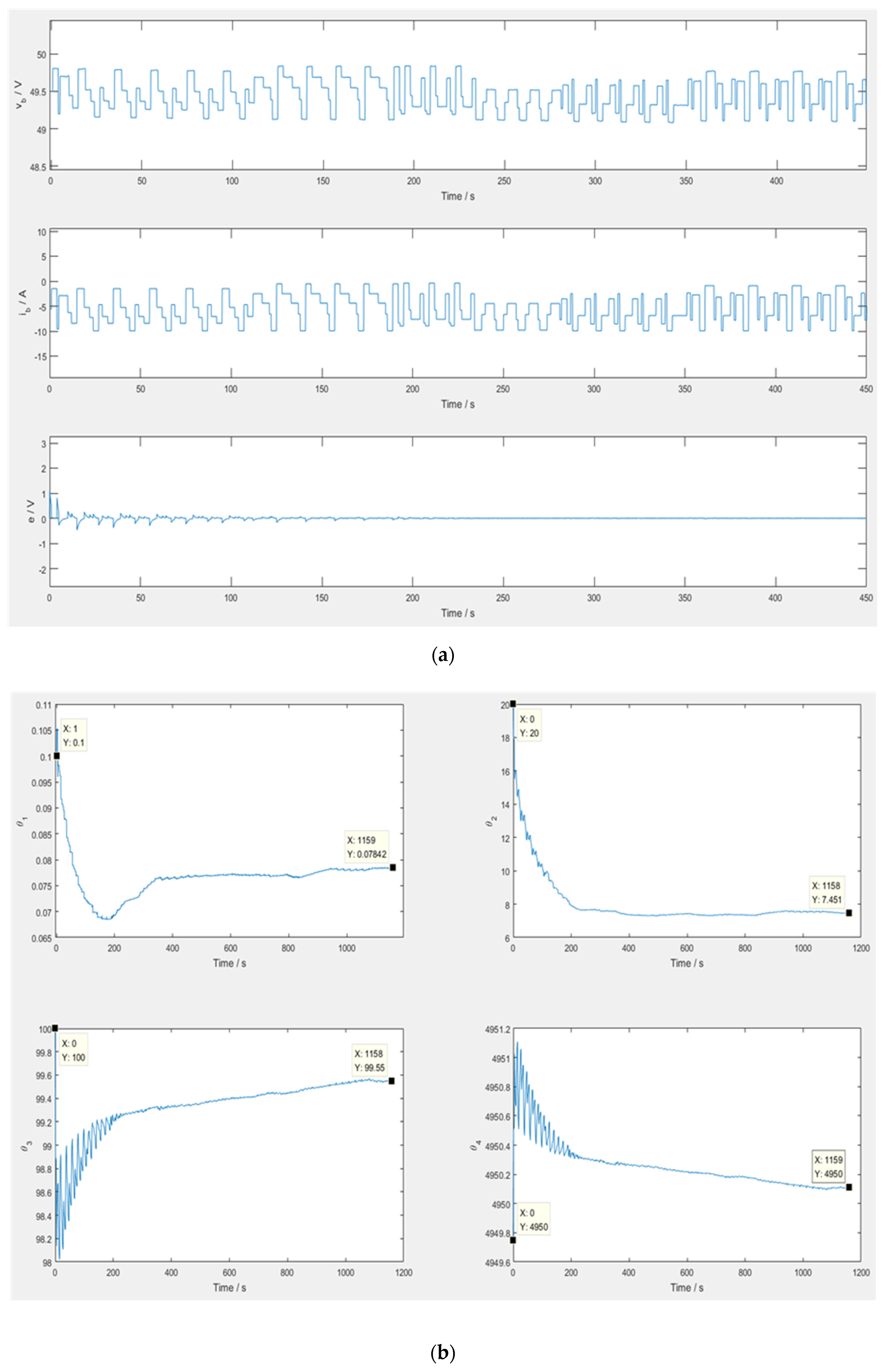
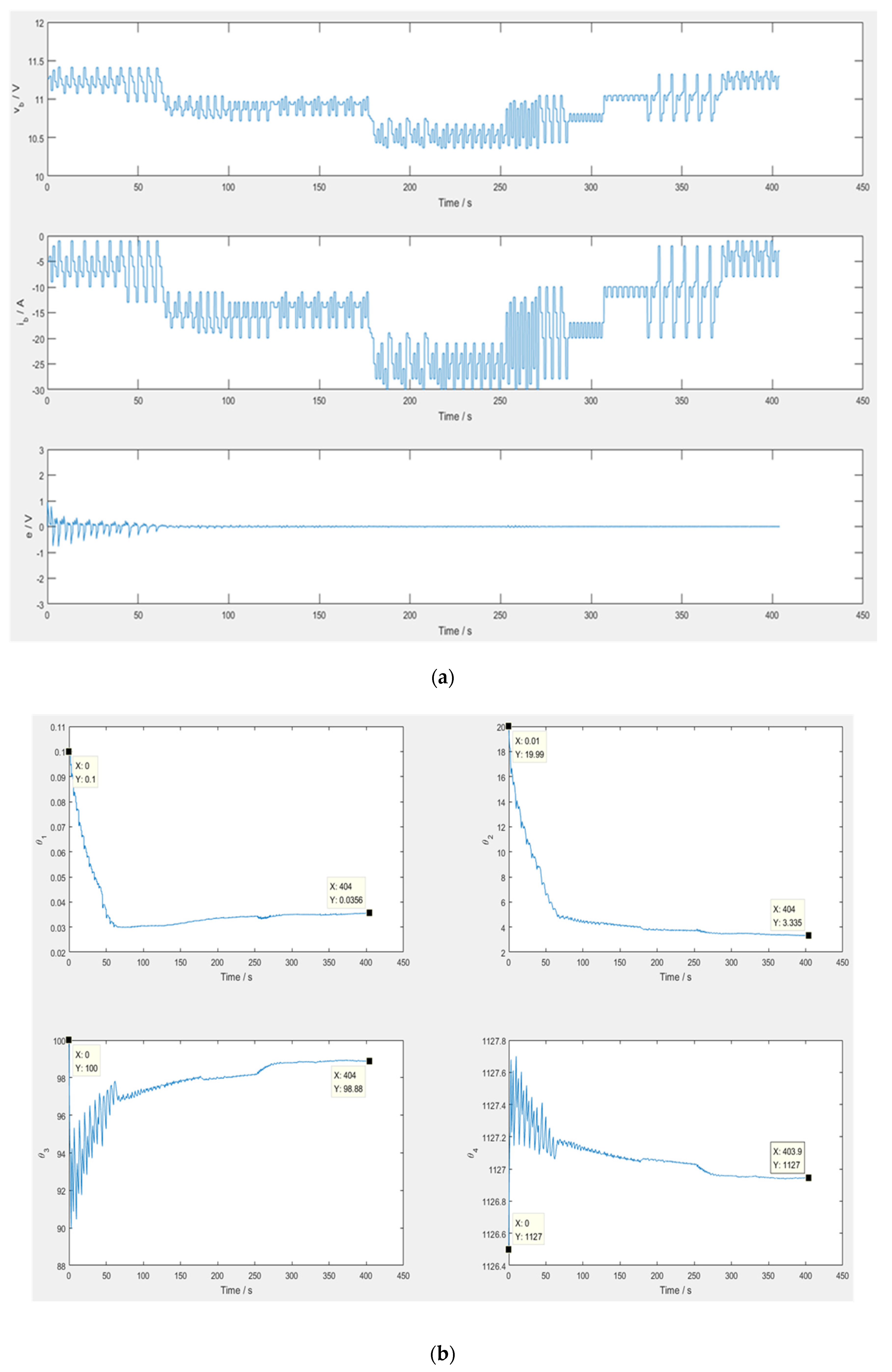
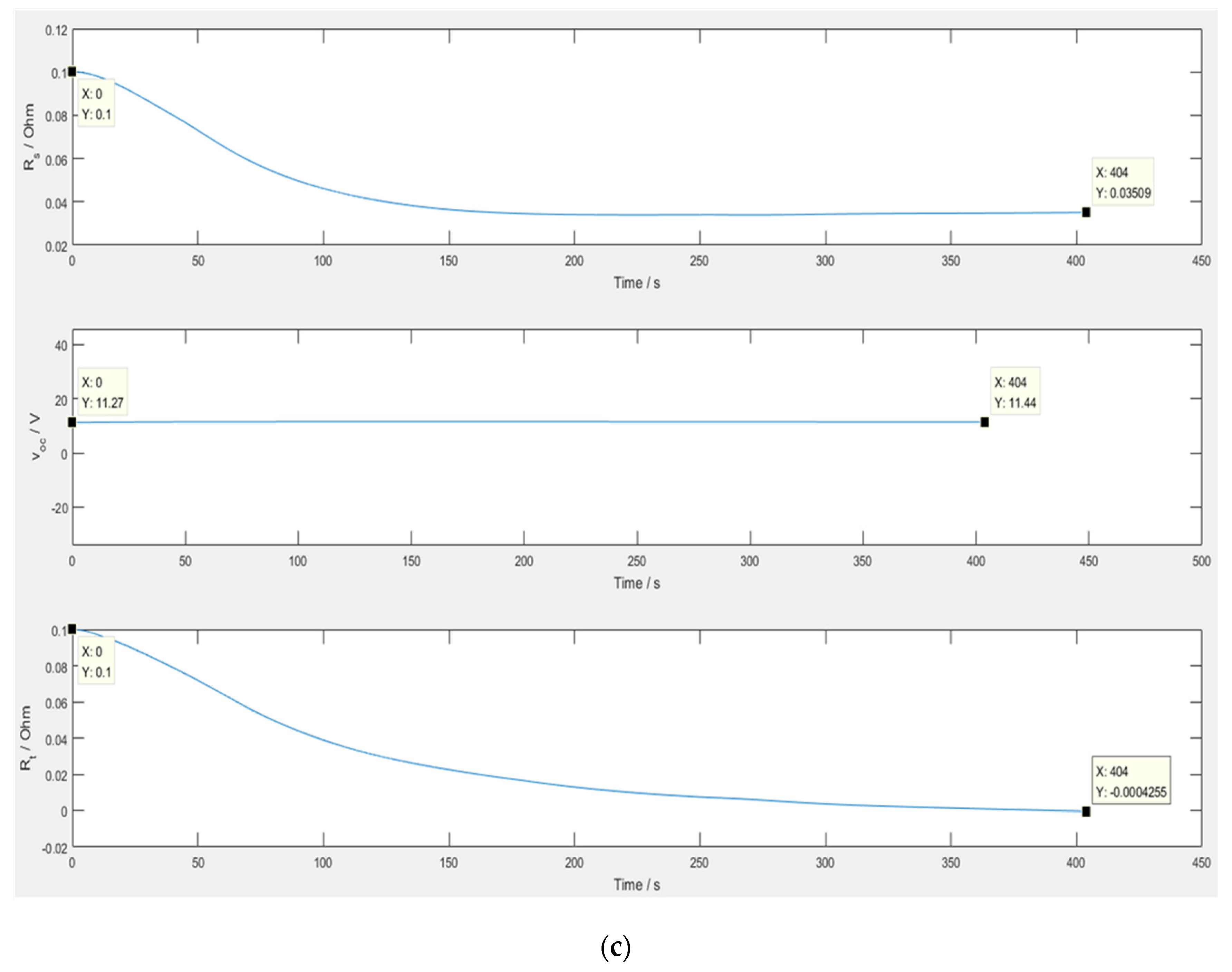
Two experiments in this section were carried out for confirming the achievability for developing an adaptive control scheme on monitoring of a reused battery’s parameters, e.g., IRs and OCV simultaneously. Here, lithium-ion batteries were selected and integrated in nominal voltages of 52 V and 50.4 V modules to simulate reused batteries. Working voltage v b and current i b of a reused battery were inputs required. According to the electrical circuit model (ECM), the estimated battery voltage was formulated through estimating model parameters, θ ^ i = 1 ~ 4 . The target estimating parameters were v o c (OCV) and internal resistances ( R s and R t ). v o c , R s , and R t can be extracted from online estimation algorithms.

5.2.1. Experiment 1

The objective of this experiment was to verify the accuracy of the proposed method of estimating IRs and OCV. One module of 12.6 V in a 50.4 V battery pack was used and composed by a random discharge current. Each discharge cycle was lower than 5 s so as to simulate a random load. Figure 7a shows voltage drop, battery current, and estimating error separately in a, b, and c. The estimating error tends to zero after 150 s.
The trajectories of estimating parameters are illustrated in Figure 7b, and the parameters, θ ^ 1 , θ ^ 2 , θ ^ 3 , and θ ^ 4 approach values of 0.1, 19.99, 100, and 1127, respectively. Rs, Rt, and OCV are listed in Figure 7c. The trajectory of ohmic resistance relates the parameter, θ ^ 1 . The polarized resistance converges to 0.03 Ω, and the OCV converges gradually from 11.27 to 11.44 V.

5.2.2. Experiment 2

To validate the compatibility of adaptive control scheme in an EV level’s voltage, a 50.4 V battery pack was applied in Experiment 2. The working voltage, current, and estimating error are shown in Figure 8a. The estimating error has converged to near zero in 150 s. The trajectories of the estimating parameters are listed in Figure 8b, the steady parameters, θ ^ 1 , θ ^ 2 , θ ^ 3 , and θ ^ 4 converge to 0.078 Ω, 7.45 F−1, 99.55 S−1, and 4950 V−1, respectively. The target parameters of R s , R t , and OCV are plotted in Figure 8c.
For checking online battery management for a battery, an offline numerical model based on a schematic method [16] was established, and is shown in Figure 9. From sudden voltage drop and voltage rise in one discharge, it is possible to roughly estimate Rs, Rt, and Ct in the figure. Then, the analytical solution of voltage drop can be derived, as listed in Figure 9. In experiment 2, battery discharges 5 A for 12 min and rests for 1 h, then repeats this pattern for 12 h, as shown in Figure 10a. In Figure 10b, the red and blue lines represent the offline numerical and online estimated results, respectively. Trends of estimating OCV and IRs estimation are close to the offline numerical model. The deviation of OCV is roughly within 2%. Furthermore, the battery pack is composed of continuous discharging patterns, as shown in Figure 11a. For OCV, the estimated values, in the green line, are compared with offline numerical results, in the red line, as shown in Figure 11b. The deviation between online and offline values in the left-hand side of Figure 11b might be due to the heat accumulated in the battery, but the trend is identical. In this study, the algorithm of OCV and internal resistance assumes the battery pack is well-ventilated and isothermal. Temperature is not considered in the calculation. As for Rt, the online values are almost overlapped with offline results, as expected.

6. Conclusions

In this study, an in-house BMS is developed for RLIB. Additional enhanced battery management is established. Adaptive control schemes in the BMS are established for estimating a battery’s IRs and OCV relative to key parameters of RLIB, e.g., SOC and SOH, respectively. Here, IRs and OCV of a battery pack are accurately extracted from working voltage and discharge current in two experiments in this study. An offline numerical model using the schematic method is applied to verify the results of the online proposed scheme. In experiment 2, results of online estimations regarding OCV and IRs show good agreement with offline numerical model. The deviation of OCV is roughly within 2%. Furthermore, a hybrid battery pack using a UC is proposed to share peak power of RLIB by adjusting the duty ratio in the BMS. It shows more constrained voltage drops of battery when increasing the duty ratio of UC. The UC effectively reduces the voltage drop and decreases the DOD of the battery in the life extension test. It is shown that enhancing battery management for an RLIB can properly estimate OCV and IRs, and actively extend the life of the battery. For a new battery, offline estimation of parameters such as OCV and IRs meet the requirement. However, enhancing online management is indispensable on safety. This study proves the achievability of this managing solution for RLIBs. In the next phase, an RLIB integrated with this in-house BMS will be arranged, for storage of the intermittent renewable energies in site, in order to evaluate the performance.

Author Contributions

Conceptualization: W.-Y.S. and Y.-H.C.; methodology: Y.-H.C.; software: W.-P.Y.; validation: W.-P.Y., W.-Y.S., and Y.-H.C.; formal analysis: W.-P.Y., W.-Y.S., and Y.-H.C.; writing—original draft preparation: W.-P.Y.; writing—review and editing: W.-Y.S. and S.-M.J.; supervision: Y.-H.C. and S.-M.J.; project administration: W.-Y.S.; funding acquisition: W.-Y.S. All authors have read and agreed to the published version of the manuscript.

Funding

This research was financially supported by the Chung Yuan Christian University (Project No: 109609432).

Conflicts of Interest

The authors declare no conflicts of interest.

Nomenclature

DODdepth of discharge, %
ECMelectrical circuit model
IGBTinsulated gate bipolar transistor
vbvoltage of battery, A
vocopen-circuit voltage (OCV), V
PWMpulse-width modulation
RLIBreused lithium-ion battery
Rsfirst-order, ohm
Rtsecond-order, ohm
ibbattery current, A
vcvoltage across RC circuit, V
IRScurrent across RC curcuit based on ECM, A
SoCstate of charge, %
Ttemperature, K
hhistorical data
uadjustable for input parameters
UCultracapacitor
θ estimated results of target parameters
Ctfirst-order capacitance based on ECM, C
Subscripts: b, c, oc, s, t: battery, capacitance, open-circuit, first-order, second-order parameter, based on ECM.

References

  1. Van der Hoek, J.P.; Mol, S.; Giorgi, S.; Ahmad, J.I.; Liu, G.; Medema, G. Energy recovery from the water cycle: Thermal energy from drinking water. Energy 2018, 162, 977–987. [Google Scholar] [CrossRef]
  2. Bala, B.K.; Alam, M.S.; Debnath, N. Energy Perspective of Climate Change: The Case of Bangladesh. Strateg. Plan. Energy Environ. 2014, 33, 6–22. [Google Scholar] [CrossRef]
  3. Wai, R.; Jhung, S. Design of energy-saving adaptive fast-charging control strategy for Li-FePO4 battery module. IET Power Electron. 2012, 5, 1684–1693. [Google Scholar] [CrossRef]
  4. Omar, N.; Daowd, M.; Hegazy, O.; Mulder, G.; Timmermans, Je.; Coosemans, T.; van den Bossche, P.; van Mierlo, J. Standardization Work for BEV and HEV Applications: Critical Appraisal of Recent Traction Battery Documents. Energies 2012, 5, 138. [Google Scholar] [CrossRef]
  5. Song, X.; Hu, S.; Chen, D.; Zhu, B. Estimation of waste battery generation and analysis of the waste battery recycling system in China. J. Ind. Ecol. 2017, 21, 57–69. [Google Scholar] [CrossRef]
  6. Provazi, K.; Campos, B.A.; Espinosa, D.C.R.; Tenório, J.A.S. Metal separation from mixed types of batteries using selective precipitation and liquid–liquid extraction techniques. Waste Manag. 2011, 31, 59–64. [Google Scholar] [CrossRef] [PubMed]
  7. Chiang, Y.-H.; Sean, W.-Y.; Wu, C.-H.; Huang, C.-Y. Development of a converterless energy management system for reusing automotive lithium-ion battery applied in smart-grid balancing. J. Clean. Prod. 2017, 156, 750–756. [Google Scholar] [CrossRef]
  8. Richa, K.; Babbitt, C.W.; Gaustad, G.; Wang, X. A future perspective on lithium-ion battery waste flows from electric vehicles. Resour. Conserv. Recycl. 2014, 83, 63–76. [Google Scholar] [CrossRef]
  9. Ahmed, R.; Sayed, M.E.; Arasaratnam, I.; Tjong, J.; Habibi, S. Reduced-Order Electrochemical Model Parameters Identification and SOC Estimation for Healthy and Aged Li-Ion Batteries Part I: Parameterization Model Development for Healthy Batteries. IEEE J. Emerg. Sel. Top. Power Electron. 2014, 2, 659–677. [Google Scholar] [CrossRef]
  10. Shareef, H.; Islam, M.M.; Mohamed, A. A review of the stage-of-the-art charging technologies, placement methodologies, and impacts of electric vehicles. Renew. Sustain. Energy Rev. 2016, 64, 403–420. [Google Scholar] [CrossRef]
  11. Zhang, Y.; Sivakumar, M.; Yang, S.; Enever, K.; Ramezanianpour, M. Application of solar energy in water treatment processes: A review. Desalination 2018, 428, 116–145. [Google Scholar] [CrossRef] [Green Version]
  12. Bendary, A.F.; Ismail, M.M. Battery Charge Management for Hybrid PV/Wind/Fuel Cell with Storage Battery. Energy Procedia 2019, 162, 107–116. [Google Scholar] [CrossRef]
  13. Ibrahim, H.; Ilinca, A.; Perron, J. Energy storage systems—Characteristics and comparisons. Renew. Sustain. Energy Rev. 2008, 12, 1221–1250. [Google Scholar] [CrossRef]
  14. Ng, K.S.; Moo, C.-S.; Chen, Y.-P.; Hsieh, Y.-C. Enhanced coulomb counting method for estimating state-of-charge and state-of-health of lithium-ion batteries. Appl. Energy 2009, 86, 1506–1511. [Google Scholar] [CrossRef]
  15. Speirs, J.; Contestabile, M.; Houari, Y.; Gross, R. The future of lithium availability for electric vehicle batteries. Renew. Sustain. Energy Rev. 2014, 35, 183–193. [Google Scholar] [CrossRef]
  16. Chiang, Y.H.; Sean, W.Y.; Ke, J.C. Online estimation of internal resistance and open-circuit voltage of lithium-ion batteries in electric vehicles. J. Power Sources 2011, 196, 3921–3932. (In English) [Google Scholar] [CrossRef]
  17. Hannan, M.A.; Lipu, M.S.H.; Hussain, A.; Mohamed, A. A review of lithium-ion battery state of charge estimation and management system in electric vehicle applications: Challenges and recommendations. Renew. Sustain. Energy Rev. 2017, 78, 834–854. [Google Scholar] [CrossRef]
  18. Shuo, P.; Farrell, J.; Jie, D.; Barth, M. Battery state-of-charge estimation. In Proceedings of the 2001 American Control Conference (Cat. No.01CH37148), Arlington, VA, USA, 25–27 June 2001; pp. 1644–1649. [Google Scholar]
  19. Salkind, A.J.; Fennie, C.; Singh, P.; Atwater, T.; Reisner, D.E. Determination of state-of-charge and state-of-health of batteries by fuzzy logic methodology. J. Power Sources 1999, 80, 293–300. [Google Scholar] [CrossRef]
  20. Farag, M. Lithium-Ion Batteries: Modelling and State of Charge Estimation. Master’s Thesis, McMaster University, Hamilton, ON, Canada, 2013. [Google Scholar]
  21. Hu, C.; Jain, G.; Tamirisa, P.; Gorka, T. Method for estimating capacity and predicting remaining useful life of lithium-ion battery. Appl. Energy 2014, 126, 182–189. [Google Scholar] [CrossRef]
  22. Wu, C.-H.; Chiang, Y.-H.; Sean, W.-Y.; Lo, S.-M.; Ke, J.-C.; Hung, Y.-H. Optimal designs and experimental verification for a hybrid energy storage system. In Proceedings of the 2010 International Symposium on Computer, Communication, Control and Automation (3CA), Tainan, Taiwan, 5–7 May 2010. [Google Scholar]
  23. Available online: http://www.mpoweruk.com/performance.htm (accessed on 1 May 2020).
  24. Marefat, H.; Jalalmaab, M.; Azad, N.L. Energy management of battery electric vehicles hybridized with supercapacitor using stochastic dynamic programming. In Proceedings of the 2018 SICE International Symposium on Control Systems (SICE ISCS), Piscataway, NJ, USA, 9–11 March 2018; pp. 199–205. [Google Scholar]
Figure 1. Basic framework of the battery management system (BMS) [17].
Energies 13 03306 g001
Figure 2. In-house battery management system: (a) basic diagram; (b) board of module monitoring unit (MMU), based on chip ISL78600; (c) operation board of BMS.
Energies 13 03306 g002
Figure 3. Adaptive control scheme in Simulink/MATLAB.
Energies 13 03306 g003
Figure 4. (a) Two battery packs in test bench (52 V and 50.4 V); (b) circuit of BMS with pulse-width modulation (PWM) control.
Energies 13 03306 g004
Figure 5. (a) Voltage drop vs. duty ratio in constant-current discharge: (b) voltage drop vs. duty ratio in pulse discharge.
Energies 13 03306 g005
Figure 6. (a) Discharge current of battery and system (battery/ultracapacitor (UC)); (b) voltage drop of battery and system.
Energies 13 03306 g006aEnergies 13 03306 g006b
Figure 7. (a) Terminal voltage, discharge current, and estimating error; (b) estimating model parameters, θ ^ i , i = 1~4; (c) estimated Rs, Rt, and voc in Experiment 1.
Energies 13 03306 g007aEnergies 13 03306 g007b
Figure 8. (a) Terminal voltage, discharge current, and estimating error; (b) estimating model parameters, θ ^ i , i = 1~4; (c) estimated Rs, Rt, and voc in Experiment 2.
Energies 13 03306 g008aEnergies 13 03306 g008b
Figure 9. An offline numerical model based on the schematic method [16] (Id: discharge current; td: discharge time).
Energies 13 03306 g009
Figure 10. (a) Voltage drop and discharge current; (b) comparison of online estimating open-circuit voltage (OCV) and internal resistances (IRs) with the offline numerical model.
Energies 13 03306 g010
Figure 11. (a) Voltage drop and discharge current; (b) comparison of online estimating OCV and Rt with the offline numerical model.
Energies 13 03306 g011

