Electromagnetic and Thermal Analysis of a Permanent Magnet Motor Considering the Effect of Articulated Robot Link


Abstract
1. Introduction
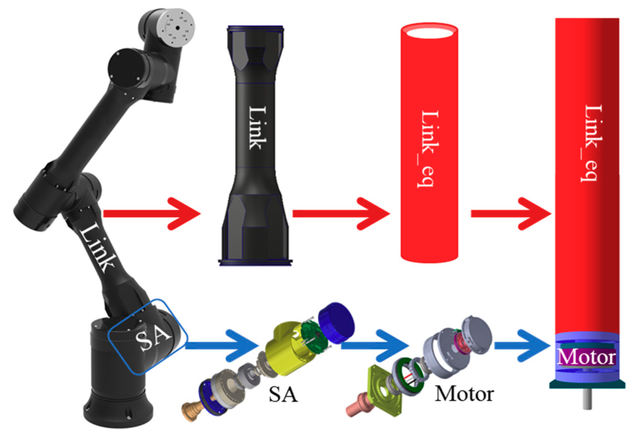
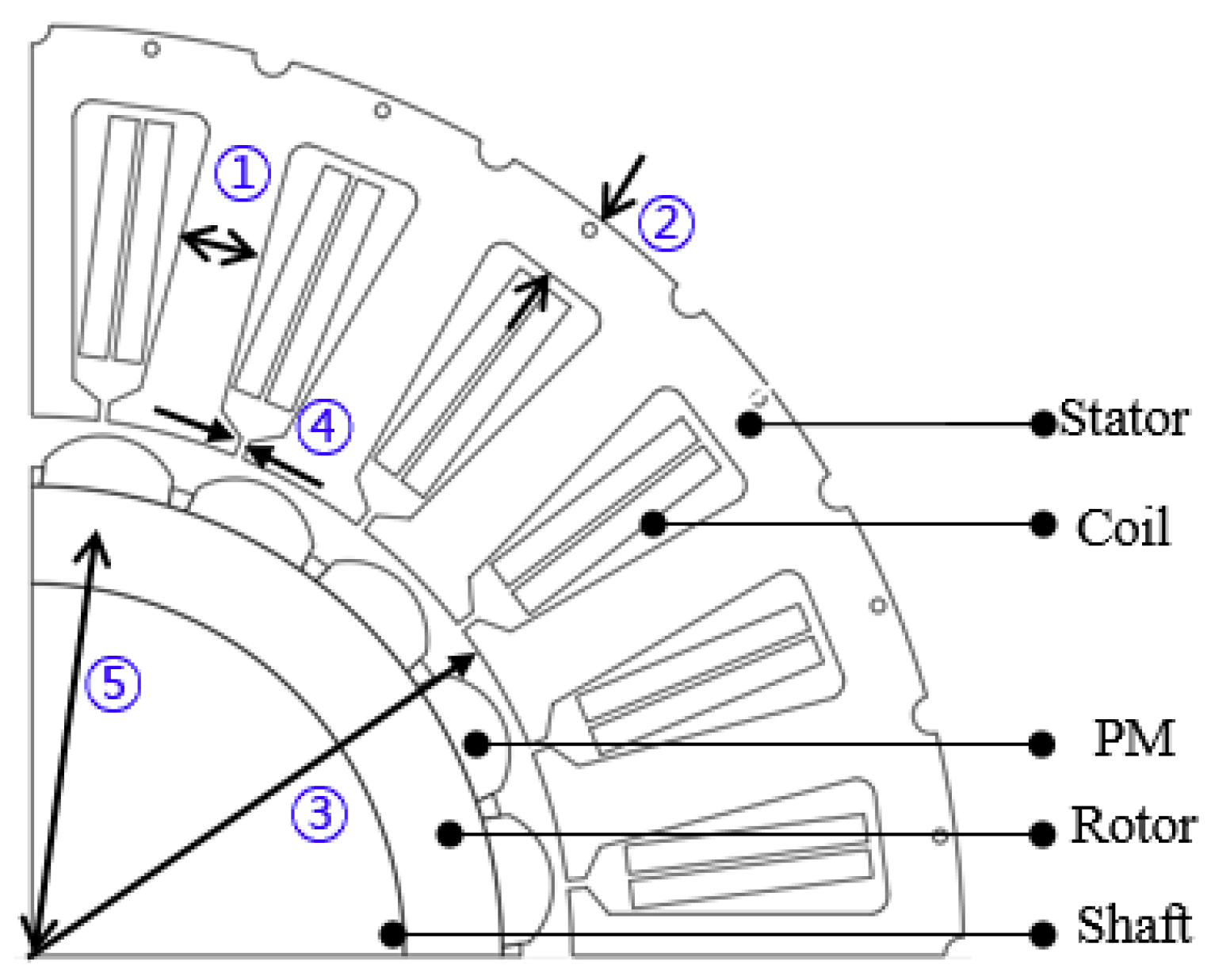
2. Designed Model
3. Electromagnetic and Thermal Investigation
3.1. Analysis Assumptions
- (1)
- The electromagnetic analysis is implemented at 80 °C. At that temperature, the residual magnetic flux density of PMs material is 1.24 Tesla.
- (2)
- The robot link is only considered in thermal analysis, not in electromagnetic analysis.
- (3)
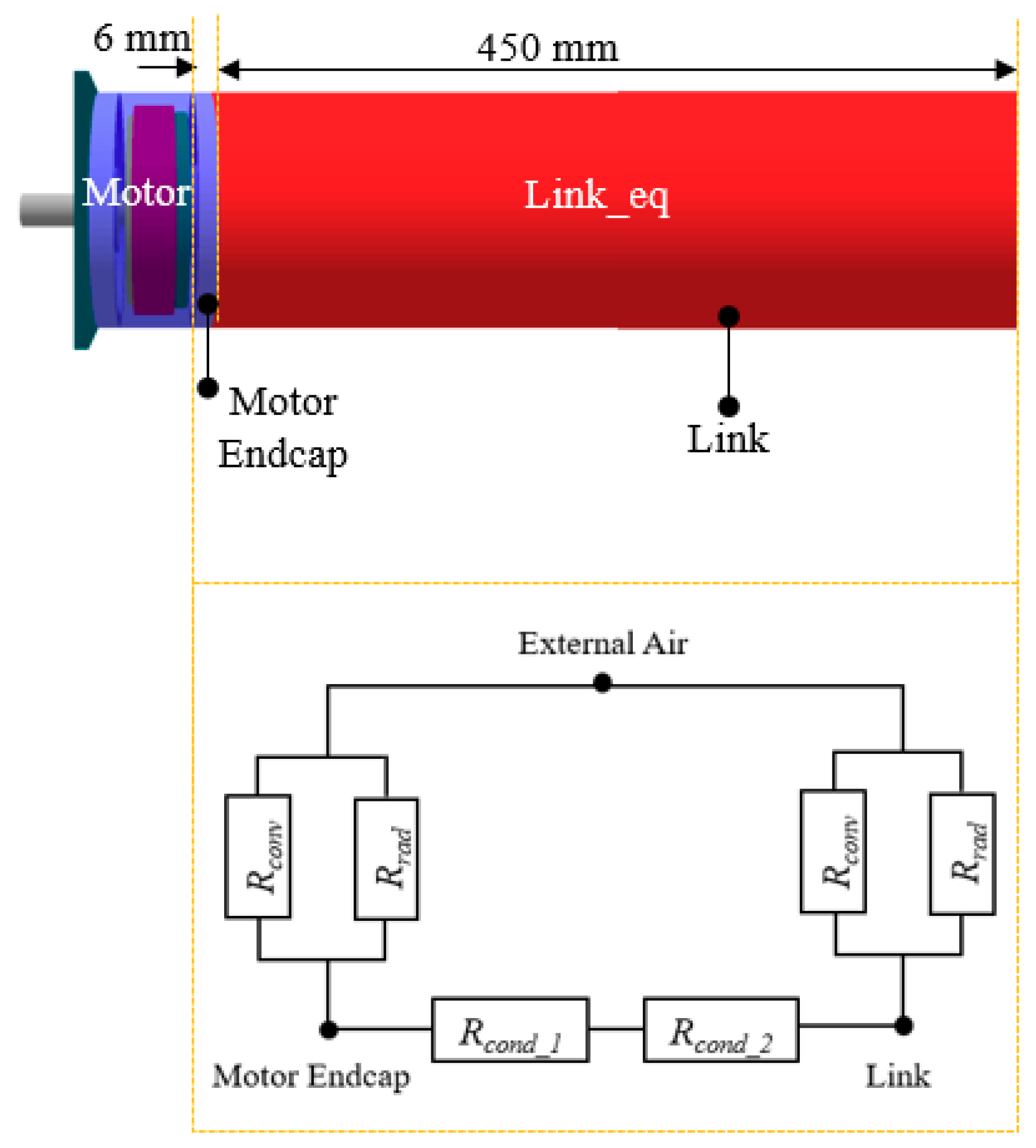
- The force convection is considered in the air gap due to rotor rotation and free convection is considered in the outer housing.
- (4)
- Ambient temperature and initial temperature of the motor are set to 17 °C.
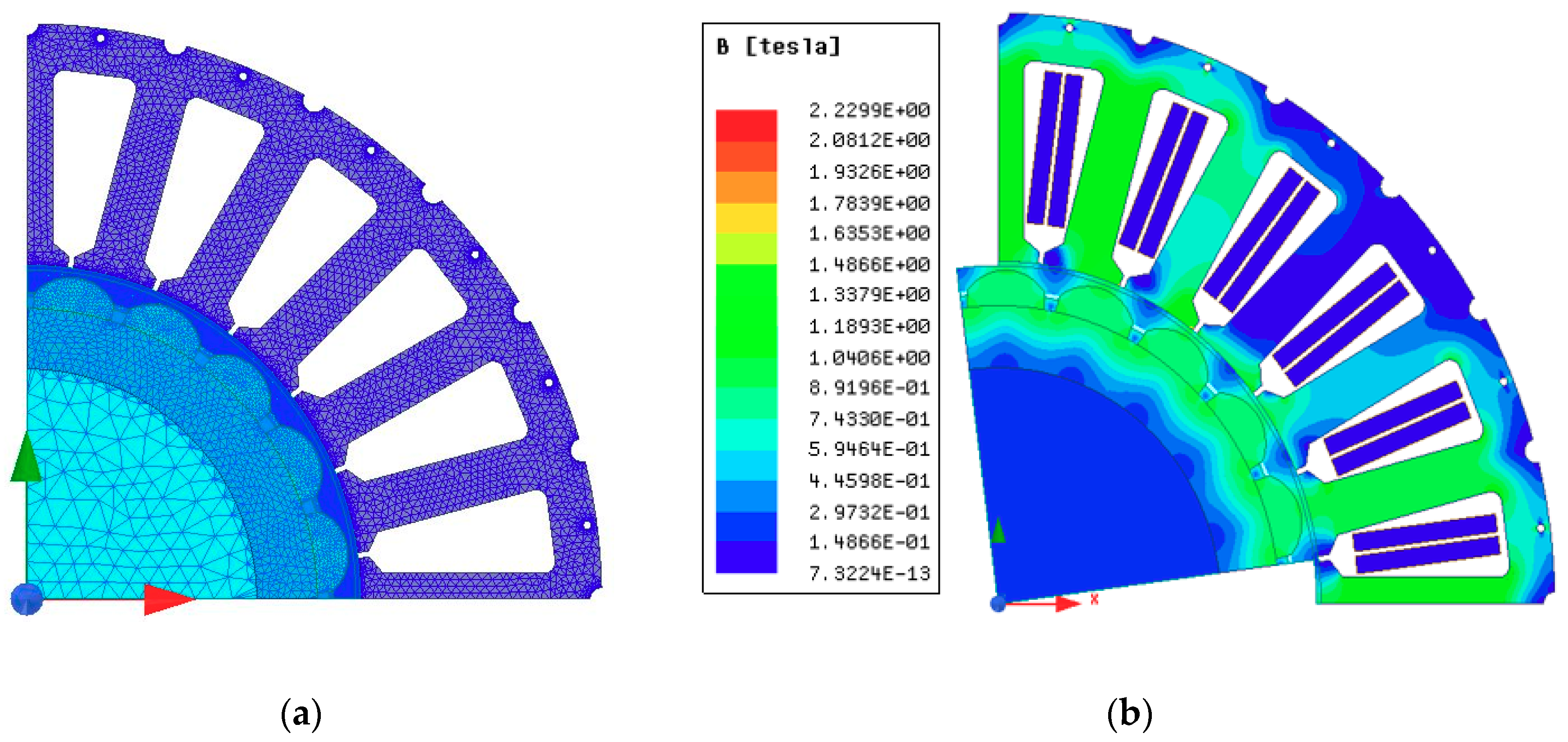
3.2. Electromagnetic Analysis
3.3. Thermal Analysis
4. Experimental Validation
5. Conclusions
Author Contributions
Funding
Acknowledgments
Conflicts of Interest
References
- Lee, K.; Lee, J.; Woo, B.; Lee, J.; Lee, Y.; Ra, S. Modeling and control of a articulated robot arm with embedded joint actuators. In Proceedings of the 2018 International Conference on Information and Communication Technology Robotics (ICT-ROBOT), Busan, Korea, 8th September 2018; pp. 1–4. [Google Scholar]
- Zhao, W.; Wang, X.; Gerada, C.; Zhang, H.; Liu, C.; Wang, Y. Multi-physics and multi-objective optimization of a high speed PMSM for high performance applications. IEEE Trans. Magn. 2018, 54, 1–5. [Google Scholar] [CrossRef]
- Kong, Y.; Lin, M.; Jia, L. A novel high power density permanent-magnet synchronous machine with wide speed range. IEEE Trans. Magn. 2020, 56, 1–6. [Google Scholar] [CrossRef]
- Li, L.; Zhang, J.; Zhang, C.; Yu, J. Research on electromagnetic and thermal issue of high-efficiency and high-power-density outer-rotor motor. IEEE Trans. Appl. Super. 2016, 26, 1–5. [Google Scholar] [CrossRef]
- Fang, S.; Liu, H.; Wang, H.; Yang, H.; Lin, H. High power density pmsm with lightweight structure and high-performance soft magnetic alloy core. IEEE Trans. Appl. Super. 2019, 29, 1–5. [Google Scholar] [CrossRef]
- Tong, W.; Sun, R.; Zhang, C.; Wu, S.; Tang, R. Loss and thermal analysis of a high-speed surface-mounted PMSM with amorphous metal stator core and titanium alloy rotor sleeve. IEEE Trans. Magn. 2019, 55, 1–4. [Google Scholar] [CrossRef]
- Luu, P.T.; Lee, J.Y.; Kim, J.W.; Chun, Y.D.; Oh, H.S. Effect of axial-layered permanent-magnet on operating temperature in outer rotor machine. J. Electr. Eng. Technol. 2018, 13, 2329–2334. [Google Scholar]
- Luu, P.T.; Lee, J.; Lee, J.; Park, J. Electromagnetic and thermal analysis of permanent-magnet synchronous motors for cooperative robot applications. IEEE Trans. Magn. 2020, 56, 1–4. [Google Scholar] [CrossRef]
- Joo, D.; Cho, J.; Woo, K.; Kim, B.; Kim, D. Electromagnetic field and thermal linked analysis of interior permanent-magnet synchronous motor for agricultural electric vehicle. IEEE Trans. Magn. 2011, 47, 4242–4245. [Google Scholar] [CrossRef]
- Fan, J.; Zhang, C.; Wang, Z.; Dong, Y.; Nino, C.E.; Tariq, A.R.; Strangas, E.G. Thermal analysis of permanent magnet motor for the electric vehicle application considering driving duty cycle. IEEE Trans. Magn. 2010, 46, 2493–2496. [Google Scholar] [CrossRef]
- Yeo, H.; Park, H.; Seo, J.; Jung, S.; Ro, J.; Jung, H. Electromagnetic and thermal analysis of a surface-mounted permanent-magnet motor with overhang structure. IEEE Trans. Magn. 2017, 53, 1–4. [Google Scholar] [CrossRef]
- Zhao, N.; Liu, W. Loss calculation and thermal analysis of surface-mounted pm motor and interior PM motor. IEEE Trans. Magn. 2015, 51, 1–4. [Google Scholar]
- Lee, J.; Yeo, H.; Jung, H.; Kim, T.; Ro, J. Electromagnetic and thermal analysis and design of a novel-structured surface-mounted permanent magnet motor with high-power-density. IET Electr. Power Appl. 2019, 13, 472–478. [Google Scholar] [CrossRef]
- Zhou, K.; Pries, J.; Hofmann, H. Computationally efficient 3-D finite-element-based dynamic thermal models of electric machines. IEEE Trans. Transp. Electrif. 2015, 1, 138–149. [Google Scholar] [CrossRef]
- Marignetti, F.; Delli Colli, V.; Coia, Y. Design of axial flux PM synchronous machines through 3-D coupled electromagnetic thermal and fluid-dynamical finite-element Analysis. IEEE Transac. Ind. Elec. 2008, 55, 3591–3601. [Google Scholar] [CrossRef]
- Zhang, Y.; McLoone, S.; Cao, W.; Qiu, F.; Gerada, C. Power loss and thermal analysis of a MW high-speed permanent magnet synchronous machine. IEEE Trans. Ener. Conv. 2017, 32, 1468–1478. [Google Scholar] [CrossRef]
- Dong, J.; Huang, Y.; Jin, L.; Lin, H.; Yang, H. Thermal optimization of a high-speed permanent magnet motor. IEEE Trans. Magn. 2014, 50, 749–752. [Google Scholar] [CrossRef]
- Koronides, A.; Krasopoulos, C.; Tsiakos, D.; Pechlivanidou, M.S.; Kladas, A. Particular coupled electromagnetic, thermal, mechanical design of high-speed permanent-magnet motor. IEEE Trans. Magn. 2020, 56, 1–5. [Google Scholar] [CrossRef]
- Kolondzovski, Z.; Arkkio, A.; Larjola, J.; Sallinen, P. Power limits of high-speed permanent-magnet electrical machines for compressor applications. IEEE Trans. Ener. Conv. 2011, 26, 73–82. [Google Scholar] [CrossRef]
- Bianchi, N.; Bolognani, S.; Frare, P. Design criteria for high-efficiency SPM synchronous motors. IEEE Trans. Ener. Conv. 2006, 21, 396–404. [Google Scholar] [CrossRef]
- Lee, J.-Y.; Kang, D.-H.; Chang, J.-H.; Hong, J.-P. Rapid eddy current loss calculation for transverse flux linear motor. Proc. IEEE Ind. Appl. Annu. Meeting 2006, 1, 400–406. [Google Scholar]


| Parameter | Value |
|---|---|
| Number of slots/poles | 20/24 |
| Rated Power | 400 W |
| Stator Outer Diameter | 100 mm |
| Air gap length | 0.75 mm |
| Axial Length | 25 mm |
| Cooling Type | Natural Cooling |
| Motor Performance | |||||
|---|---|---|---|---|---|
| Current Density (Arms/mm2) | Line Back Electromotive Force at 3200 rpm (Vrms) | Cogging Torque (mNm) | Efficiency (%) | ||
| 5.8 | 26.81 | 2.5 | 87.7 | ||
| Loss Data at 80 °C (W) | |||||
| Stator core loss | Rotor core loss | Copper loss | |||
| 24.6 | 0.33 | 11.27 | |||
| Convective Heat Transfer | Radiative Heat Transfer | |
|---|---|---|
| Housing Outside | 5.8 | 5.6 |
| Air gap | 49.01 | - |
| Link | 6.3 | 5.9 |
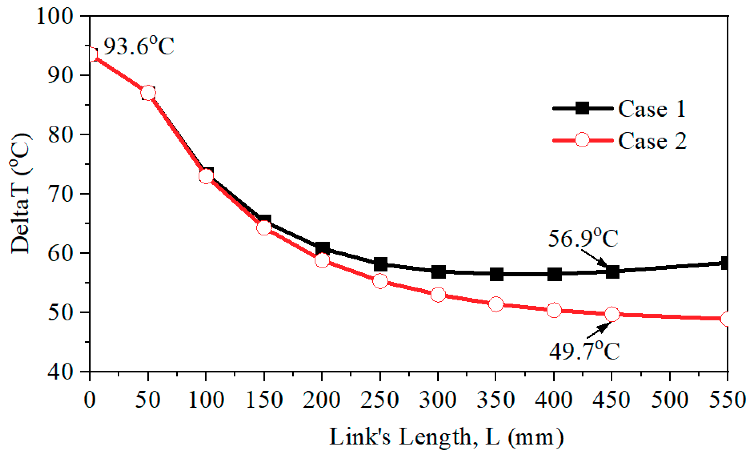
| Link’s length, L = 300 mm | ||
| Simulation_Case 1 | Simulation_Case 2 | Experiment |
| 56.8 | 52.5 | 52.7 |
| Link’s length, L = 450 mm | ||
| Simulation_Case 1 | Simulation_Case 2 | Experiment |
| 56.9 | 49.7 | 49.5 |
© 2020 by the authors. Licensee MDPI, Basel, Switzerland. This article is an open access article distributed under the terms and conditions of the Creative Commons Attribution (CC BY) license (http://creativecommons.org/licenses/by/4.0/).
Share and Cite
Luu, P.T.; Lee, J.-Y.; Lee, J.-H.; Park, J.-W. Electromagnetic and Thermal Analysis of a Permanent Magnet Motor Considering the Effect of Articulated Robot Link. Energies 2020, 13, 3239. https://doi.org/10.3390/en13123239
Luu PT, Lee J-Y, Lee J-H, Park J-W. Electromagnetic and Thermal Analysis of a Permanent Magnet Motor Considering the Effect of Articulated Robot Link. Energies. 2020; 13(12):3239. https://doi.org/10.3390/en13123239
Chicago/Turabian StyleLuu, Phuong Thi, Ji-Young Lee, Ji-Heon Lee, and Jung-Woo Park. 2020. "Electromagnetic and Thermal Analysis of a Permanent Magnet Motor Considering the Effect of Articulated Robot Link" Energies 13, no. 12: 3239. https://doi.org/10.3390/en13123239
APA StyleLuu, P. T., Lee, J.-Y., Lee, J.-H., & Park, J.-W. (2020). Electromagnetic and Thermal Analysis of a Permanent Magnet Motor Considering the Effect of Articulated Robot Link. Energies, 13(12), 3239. https://doi.org/10.3390/en13123239