Abstract
This paper deals with the computation of the performance characteristics of the single-phase self-excited induction generator by field–circuit method. It presents and compares previously unpublished results—self-excitation and no-load characteristics of the generator for different rotor speeds, and complete load steady-state performance characteristics for various types of the core materials. The discrepancies between the performance characteristics of the generator for the catalog’s magnetization curves of different types of electrical sheets and for an actual magnetic core of the generator for self-excitation transients and load steady-state are presented. The results may be useful for designing new constructions of single-phase self-excited induction generators.
1. Introduction
Single-phase self-excited induction generators (SP-SEIG) driven by a small hydro or wind turbine may be utilized as an auxiliary source of energy in households, or as a primary electrical energy source in remote areas. Self-excited induction generators (SEIG) seem to be an alternative to synchronous generators for small autonomous energy systems. Despite the fact that they have an inherently unsatisfactory frequency and voltage regulation, their construction is robust and manufacturing as well as maintenance costs are low. Therefore, they can be employed in simple or more complex small power systems. The authors in paper [1] present a micro-grid system supplied by three sources of electrical energy: a small hydro-turbine driven SP-SEIG, a brushless DC generator driven by a wind turbine, and a photovoltaic array, supplemented with a battery storage system. The authors presented a system that kept the voltage and frequency stable under changing loads and varying energy levels injected into the micro-grid from the different sources. A similar digital signal processorbased control scheme was employed for efficient control of the diesel engine driving SP-SEIG [2] for operation of the prime mover at maximum efficiency, as the electric load was changing. In [3], Kalla et al. present a simpler voltage controller, made of off-the-shelf electronic components. The controller regulates the output voltage within 5% at variable resistive, inductive and dynamic resistive–inductive loads (induction motor), as well as at varying prime mover speeds. In order to supply large power single-phase loads, the Steinmetz-connected three-phase induction generator with a single-phase output may be employed [4]. Zhong et al., in [5], present a novel windings connection of a three-phase SEIG, where a single-phase load is connected to the generator through two excitation capacitors, and an optimization method that ensures the minimum imbalance of the phase currents was proposed. The authors in [6] developed a new formulation of the SEIG model, with an uncomplicated method for the determination of the machine’s operating point. The method can be implemented in a low-cost controller. Kim et al., in [7], present a new idea for an induction generator with a single-phase output based on a three-phase induction motor. The stator windings were separated, two of them were excited by two independent sources (inverters powered by a battery storage system) and the load was connected to the third phase. The obtained results indicate that the method allows the generation of electrical energy at a constant frequency under a variable prime mover speed, while the voltage regulation needs some improvement, e.g., by the application of a closed-loop control system. In autonomous single-phase induction generators with a cage rotor to initiate the self-excitation process, the remnant flux density in the rotor core has to be nonzero, which produces an electromotive force on the stator windings and thus voltage build-up takes place. The magnetization curve of the induction generators has to be nonlinear due to the magnetic saturation of the core to provide the intersection of the magnetization curve with the capacitor voltage characteristic (straight line). The no-load terminal voltage increases until the voltage reaches a certain value, which depends on speed, excitation capacitance and generator parameters. The increase in the terminal voltage over time depends on the shape of the generator’s magnetization curve (linear and saturation zones). As shown in Figure 1, the magnetization curves of the laminated core assembly of the induction generator and electric sheets used for generator’s core materials differ widely due to an air gap and the slotting in of the stator and rotor of the induction generator. Furthermore, the deterioration of the magnetization curve also depends on the technology used for the slotting of electrical sheets (punching or laser cutting). An application of the different magnetization characteristics of the core material and its influence on performance characteristics of single-phase induction generators was also analyzed in [8], using a steady-state equivalent circuit method. With regard to the considerable differences between the magnetization curve of the generator’s laminated core and that of an electrical sheet, this paper presents the simulation study of the performance characteristics of the single-phase self-excited induction generator based on the field–circuit computations for steel cores made of electrical sheets, only taking into account their different magnetization curves given by the manufacturers.
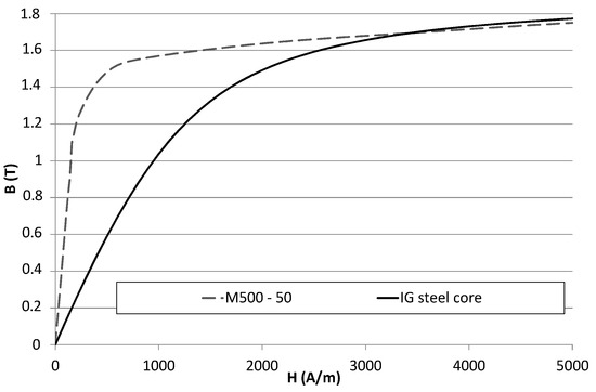
Figure 1.
Magnetization curve of core of induction generator (IG iron core) compared to that of the M500 electrical sheet.
2. Field–Circuit Method for the Simulation of Generator Self-Excitation and Work
In this paper, a coupled field and circuit approach is adopted for the performance analysis of a single-phase self-excited induction generator [9,10]. The following simplifying assumptions have been applied:
- To analyze the self-excitation phenomenon in the generator, a two-dimensional, time-stepping finite element method for the magnetic field computation is used.
- A constant rotor speed is assumed.
- The hysteresis effect on the magnetic core is neglected.
In order to study the machine, we have to solve two-dimensional Maxwell equations using a magnetic vector potential formulation:
where A [0, 0, A(x,y,t)] is the magnetic vector potential; Js [0, 0, Js(x,y,t)], the current density in the stator slots; ν, the reluctivity of magnetic material; and σ, the electric conductivity. The rotor bars are treated in the field–circuit model as thick (bulk) conductors; therefore, in Equation (1) there is an algebraic sum of two components of current density: Jb [0, 0, Jb(x,y,t)], the current density for a DC current, and , the additional component created by the rotor current redistribution due to the rotor skin effect.
The induction machine chosen for the study was a 1.1 kW, four-pole, 50 Hz, two-winding, off-the-shelf single-phase capacitor induction motor. The ratings and other motor data are listed in Table 1.

Table 1.
Ratings and basic dimensions of the induction machine.
In Figure 2, the finite elements mesh of a cross-section of a modeled single-phase self-excited induction generator is shown. The mesh contains about 22,000 nodes and consists mostly of second-order triangular and quadrilateral elements in yokes, trapezoidal parts of slots, and the teeth of the magnetic core.
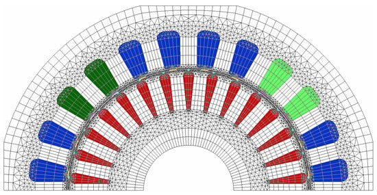
Figure 2.
FE mesh of 2D field–circuit model of the single-phase induction generator.
In the stator of the single-phase induction generator, there are two-phase windings, i.e., a main winding (M) that is symmetrically located (distributed) along with the periphery of the stator in the 16th stator slots. The electrical output load of the generator (ZL) is connected to its terminals. The second winding, i.e., the auxiliary stator winding occupies only 1/3 of the stator slots, to which the excitation capacitor (Cex) is connected in parallel to ensure the self-excitation process in the generator (Figure 3). In order to intensify the self-excitation in the generator, the supported shunt capacitor (Csh) in the load stator winding is also applied. In the rotor, there is an aluminum cage made of 30 drop-shaped bars symmetrically distributed around the rotor periphery and short-circuited by end-rings. The rotor bars, different from stator windings, are treated as solid conductors in this model and skin effect should be taken into account. The rotor circuit is presented in Figure 4b. The rotor end-rings in this two-dimensional field model are assumed to be constant parameters of the rotor cage since the leakage field of the end-rings cannot be taken into account when calculating a 2D field in a cross-section of the machine (Figure 2). These parameters were determined by classical formulas. The mechanical shaft of the generator was made of non-magnetic steel and, therefore, it was possible to assume Dirichlet’s boundary conditions on the inner diameter of the rotor core. Some principal outer parameters of the generator such as the excitation capacitor and shunt capacitor, were not changed under investigation (assuming fixed values of Cex = 30 uF and Csh = 15 uF, which were selected experimentally) and were selected so as to ensure the self-excitation voltage at no-load of the rated value at the generator’s terminals.
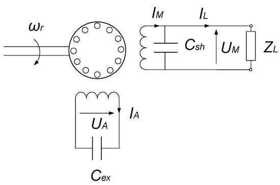
Figure 3.
The generator configuration with excitation and shunt capacitors in stator windings.
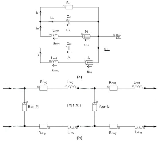
Figure 4.
Equivalent electrical circuit of the single-phase self-excited induction generator (SP-SEIG): (a) stator circuit; (b) rotor cage circuit.
The equivalent circuit of the SP-SEIG is shown in Figure 4a. The coil conductor components M and A correspond to the regions of the main and auxiliary winding, respectively, in the finite element’s domain. They represent the parts of the windings that are placed in the slots, including the flux linkage and also the total resistance of the windings. The inductors LewM and LewA are the constant end-connection leakage inductances of the main and auxiliary winding. The squirrel symbol in Figure 4a represents the rotor cage circuit, which is shown in detail in Figure 4b. The stator circuit is described by a first-order differential system of equations with constant coefficients:
where uM, uA are the terminal voltages of the main and auxiliary windings; uxM, uxA, the voltages of the element representing the FEM coupling; uewM, uewA, the voltage drops across end connection inductances; iM, iA, the main and auxiliary windings currents; iL, the load current; and ish, the shunt capacitor current. Since there are no external voltage sources in the stator circuit, the right-hand side of Equations (2)–(3) is zero. Self-excitation is triggered by non-zero initial conditions.
The rotor bars were modeled as solid aluminum conductors, while the rotor end rings were assumed to be circuit elements of constant values—resistors (Rring) and inductors (Lring), representing the resistances and leakage reactances of the inter-bar sections. The elements representing the N bars in Figure 4b are denoted as Bar M and Bar N for the two neighboring rotor bars. The stator winding end–connection leakage inductances and resistance as well as the rotor cage end-rings resistance and leakage inductances were calculated from the classical formulas [11].
3. Performance Characteristics for Different Types of Electrical Sheets
The waveforms of the main stator voltage during the self-excitation of the generator for the magnetization curve of the generator’s core obtained by a no-load test of the actual generator [10] and for the magnetization curve of the M500 electrical sheet are presented, respectively, in Figure 5.
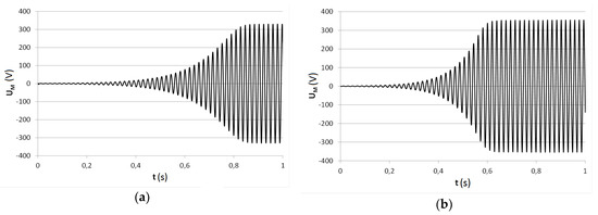
Figure 5.
Self-excitation waveform of main stator voltage for: (a) magnetization curve of generator’s core (IG steel core); (b) M500 magnetization curve.
As seen here, there are noticeable differences in the value and time of the induced terminal voltage at no-load for both cases, which reflect the different shapes of both of the magnetization curves. When applying other kinds of electrical sheets, e.g., M330, M470, M530 and M700, which are commonly used for laminated iron cores in induction machines (Figure 6), very similar waveforms of self-excitation voltage and steady-state load characteristics of the generator were obtained, since the magnetization characteristics of electrical sheets are close to each other (Figure 7).
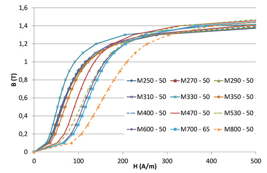
Figure 6.
Magnetization curves of non-grain-oriented electrical sheets.
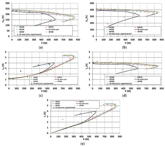
Figure 7.
Output characteristics of the generator for various electrical sheets: (a) main winding voltage vs. output power; (b) main winding current vs. output power; (c) auxiliary winding voltage vs. output power; (d) auxiliary winding current vs. output power; (e) load current vs. output power.
The no-load steady-state terminal voltages of the generator as a function of the rotor speed for various magnetization characteristics of electrical sheets are presented in Figure 8.
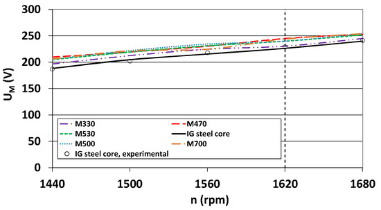
Figure 8.
No-load main stator winding voltage vs. rotor speed of generator for various electrical sheets.
The values of the no-load terminal voltages of the generator at nominal speed n = 1620 rpm for the different types of electrical sheets are listed in Table 2.

Table 2.
No-load terminal voltage of the generator at 1620 rpm for various types of electrical sheets.
In Figure 9, waveforms of the main winding voltages at no-load for selected types of steel are shown. The shape of the voltage is affected by magnetic saturation of the core, but there are no significant differences between the waveforms regarding the different types of the steel.
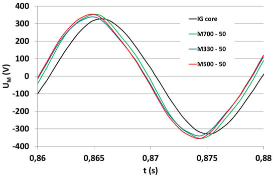
Figure 9.
Waveforms of no-load main winding voltages of the generator for M330 magnetization curve (blue), M500 magnetization curve (red), M700 magnetization curve (green) and magnetization curve of generator’s core (IG steel core, (black)).
The flux density charts of the cross-section of the generator are presented in Figure 10. Some differences in the flux density distribution can be noticed, most notably that the stator and rotor flux density for the M500 and M700 sheets exceeds 1.7 T. This implies larger core loss and lower efficiency, and also lower capacitance required to reach the rated value of no-load voltage.
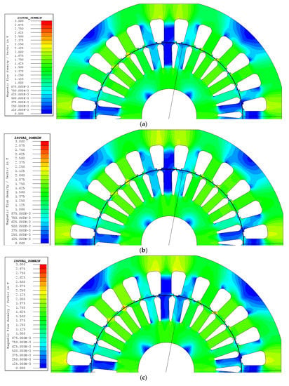
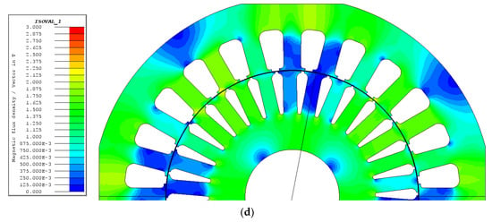
Figure 10.
Flux density distribution charts of the generator for (a) M330 magnetization curve, (b) M500 magnetization curve, (c) M700 magnetization curve and (d) magnetization curve of generator’s core (IG steel core).
4. Conclusions
The calculation of the output characteristics of the single-phase self-excited induction generator when applying magnetization characteristics delivered by manufacturers leads to an overestimation of the performance of an actual generator regarding the maximum output power—the differences may be as much as 40%. No-load terminal voltages are also overestimated with respect to the voltage of the real generator by about 10%. The only good agreement of simulated load characteristics with experimental ones could be obtained when actual magnetization characteristics of a steel laminated core are employed in the field–circuit model of the generator. Unfortunately, there are still some differences between the simulation and experimental characteristics since they are mainly caused by neglecting iron losses in the field–circuit calculation. Therefore, further investigations should also take into account the magnetic losses in the core of the single-phase self-excited induction generator for a more precise prediction of the transient and steady-state performance characteristics.
Author Contributions
Conceptualization, K.M.; methodology, K.M.; validation, K.M. and A.L.; formal analysis, K.M. and A.L.; investigation, K.M and A.L.; resources, K.M.; data curation, A.L.; writing—Original draft preparation, K.M.; writing—Review and editing, A.L.; visualization, A.L.; supervision, K.M.; project administration, K.M. All authors have read and agreed to the published version of the manuscript.
Funding
This research received no external funding.
Conflicts of Interest
The authors declare no conflict of interest.
References
- Kalla, U.K.; Singh, B.P.; Murthy, S.S.; Jain, C.; Kant, K. Adaptive Sliding Mode Control of Standalone Single-Phase Microgrid Using Hydro, Wind, and Solar PV Array-Based Generation. IEEE Trans. Smart Grid 2017, 9, 6806–6814. [Google Scholar] [CrossRef]
- Kalla, U.K.; Singh, B.P.; Murthy, S.S. Green Controller for Efficient Diesel Engine Driven Single-Phase SEIG Using Maximum Efficiency Point Operation. IEEE Trans. Ind. Electron. 2016, 64, 264–274. [Google Scholar] [CrossRef]
- Kalla, U.K.; Singh, B.P.; Murthy, S.S. Implementation of Voltage Controller of Single-phase Self-excited Induction Generator. Electr. Power Compon. Syst. 2016, 44, 1–15. [Google Scholar] [CrossRef]
- Shah, M.; Somkun, S. Efficiency Evaluation of Three Phase and Single Phase C2C Self-Excited Induction Generator for Micro Hydro Power Application. Energy Procedia 2017, 138, 193–198. [Google Scholar] [CrossRef]
- Zhong, H.; Wang, B.; Wu, C.; Wang, J. Performance analysis of three-phase self-excited induction generator under single-phase load. In Proceedings of the 19th International Conference on Electrical Machines and Systems (ICEMS), Chiba, Japan, 13–16 November 2016; Available online: https://ieeexplore.ieee.org/document/7837340 (accessed on 18 June 2020).
- Benhacine, T.Z.E.; Nesba, A.; Mekhtoub, S.; Ibtiouen, R. A new approach for steady state analysis of three-phase SEIG feeding single-phase load. Compel–Int. J. Comput. Math. Electr. Electron. Eng. 2019, 38, 46–67. [Google Scholar] [CrossRef]
- Kim, B.; Pietrzak-David, M.; Maussion, P.; Bun, L. Novel structure of single-phase generator from three-phase induction machine: Modeling and simulation. In Proceedings of the IECON 2017–43rd Annual Conference of the IEEE Industrial Electronics Society Institute of Electrical and Electronics Engineers (IEEE), Beijing, China, 29 October–1 Novemeber 2017; pp. 7653–7659. [Google Scholar]
- Murthy, S.S.; Singh, B.; Sandeep, V. Design-based computational procedure for performance prediction and analysis of single-phase self-excited induction generator. IET Electr. Power Appl. 2013, 7, 477–486. [Google Scholar] [CrossRef]
- Arkkio, A. Analysis of Induction Motors Based on the Numerical Solution of the Magnetic Field and Circuit Equations D. Doctoral Thesis, Helsinki University of Technology, Helsinki, Finland, 1987. Available online: https://aaltodoc.aalto.fi/handle/123456789/2158 (accessed on 18 June 2020).
- Makowski, K.; Leicht, A. Field-circuit analysis and measurements of a single-phase self-excited induction generator. Open Phys. 2017, 15, 913–917. [Google Scholar] [CrossRef][Green Version]
- Boldea, I.; Nasar, S.A. The Induction Machine Handbook; Informa UK Limited: London, UK, 2010. [Google Scholar]
© 2020 by the authors. Licensee MDPI, Basel, Switzerland. This article is an open access article distributed under the terms and conditions of the Creative Commons Attribution (CC BY) license (http://creativecommons.org/licenses/by/4.0/).