Article

Axial-Flux Permanent-Magnet Dual-Rotor Generator for a Counter-Rotating Wind Turbine

by
Filip Kutt
*,†,
Krzysztof Blecharz
and
Dariusz Karkosiński
Faculty of Electrical and Control Engineering, Gdańsk University of Technology, 80-233 Gdańsk, Poland
*
Author to whom correspondence should be addressed.
These authors contributed equally to this work.
Energies 2020, 13(11), 2833; https://doi.org/10.3390/en13112833
Submission received: 31 March 2020 / Revised: 26 May 2020 / Accepted: 26 May 2020 / Published: 2 June 2020
(This article belongs to the Special Issue Electrical Machine Design 2020)

Abstract

:
Coaxial counter-rotating propellers have been widely applied in ships and helicopters for improving the propulsion efficiency and offsetting system reactive torques. Lately, the counter-rotating concept has been introduced into the wind turbine design. Distributed wind power generation systems often require a novel approach in generator design. In this paper, prototype development of axial-flux generator with a counter-rotating field and armature is presented. The design process was composed of three main steps: analytical calculation, FEM simulation and prototype experimental measurements. The key aspect in the prototype development was the mechanical construction of two rotating components of the generator. Sturdy construction was achieved using two points of contact between both rotors via the placement of the bearing between the inner and outer rotor. The experimental analysis of the prototype generator has been conducted in the laboratory at the dynamometer test stand equipped with a torque sensor. The general premise for the development of such a machine was an investigation into the possibility of developing a dual rotor wind turbine. The proposed solution had to meet certain criteria such as relatively simple construction of the generator and the direct coupling between the generator and the wind turbines. The simple construction and the lack of any gearbox would allow for such a system to be constructed relatively cheaply, which is a key aspect in further system development.

1. Introduction

Distributed wind power generation systems often require a novel approach in generator design, especially for low power machines. Gearless wind generator designs are particularly preferred for these applications. Lately, the counter-rotating concept has been introduced into the wind turbine design. The counter-rotating type of wind turbines has usually two sets of blades that rotate in opposite directions.
The process of converting the kinetic energy of wind into mechanical energy of rotational motion of rotating masses using a single-rotor wind turbine in accordance with the Betz’s law [1] is limited to 59% of available wind energy. In the theoretical case of an ideal wind turbine with one rotor at the optimal operating point, the speed of the air stream behind the turbine is reduced to 2/3 of the speed in front of the turbine. The counter-rotating wind turbine (CRWT) concept assumes the use of kinetic energy remaining in the airstream behind the first rotor. The use of a second counter-rotating rotor in the axis of rotation of the first rotor in accordance with the extended Betz’s theory, called Newman theory [1], allows the production of 13% more power compared to a single-rotor wind turbine. An interesting analysis regarding the increase in efficiency of an extensive wind farm with CRWTs is presented in the article [2]. In the publication [3], the authors show numerical analysis using a computational fluid dynamics (CFD) method, in which the results of simulation clearly confirm the greater efficiency of CRWT. The results of experimental research carried out on a small turbine model, shown in [4] also confirm a good performance of CRWT.
The use of a second wind rotor in the turbine increases the efficiency of wind energy conversion to a theoretical level of 64%, however, it creates mechanical problems when designing generator systems. Despite these problems, the continuous increase of installed wind turbines power focuses the researcher’s interest in searching for new forms of construction of electric generators cooperating with this type of wind turbine.
The paper [5] is one of the first to describe a mechanism that composes of two counter-rotating rotors. In the generator, a rotor is driven by one wind wheel turbine and a regular stator driven by another wind wheel turbine. Owing to the opposed rotation of two wind wheels turbines, the relative speed between the two rotors may be doubled, and thus, the efficiency is correspondingly increased, compared with a conventional generator having one rotor. Similarly, the author of [6] developed a wind turbine equipped with two sets of blades that propel the rotor and stator directly. In articles [7,8], the authors proposed a differential planetary gearing for more equilibrated torques between both rotors. This solution has been tested on low-power prototypes.
Aiming to extend the use of CRWTs to medium- and large-scale applications, the latest paper [9] introduces and analyses a higher-performance solution, which integrates two counter-rotating wind rotors, a one degree of freedom planetary speed increaser with four inputs and outputs, and a counter-rotating electric generator. The proposed system yields the following benefits: a compact design, increase of the output power (which makes it suitable for medium- and large-scale wind turbines) and allows for more efficient operation of the electric generator.
One of the most common solutions for a small wind turbine generator is the axial flux machine. In this type of machine, the normal component of the air gap flux density vector is parallel to the axis of rotation of the rotor, whereas in the typical electric machine it is perpendicular to the rotor rotation axis. There are several solutions for axial flux machine construction in regards to the magnetic circuit design and the design of the windings [10,11,12,13]. The magnetic circuit design can be single or double-sided with slotted, ring-shaped or coreless armature design and disc-shaped or coreless permanent magnet (PM) exciter design. The winding can also be designed in various ways: using multiphase distributed winding in slots, toroidal winding on a ring-shaped core and distributed or concentrated coreless winding. The most popular construction is that of the single or dual permanent magnet disc-shaped excitation core and coreless armature with concentrated single or dual-layer winding. For example, the paper [14] has already discussed the development of an axial flux permanent-magnet generator for gearless wind energy. The merits of an axial-flux generator topology are discussed with reference to the particular requirements of an electrical generator for a direct-coupled wind turbine application. The design, construction and test results of a 5 kW permanent-magnet generator were presented.
The bibliography of the subject of this article is rich. In particular, a series of publications [15,16,17,18,19] is also dedicated to the models and design of dual-rotor radial flux generators. It seems a very detailed analytical and FEM model presented in the paper [16] for dual rotor radial flux wind generators based on the equivalent magnetic circuit method. This model was developed to predict the flux densities of the inner and outer air gaps, flux densities of the rotor and stator yokes, back electromotive force (EMF), electromagnetic torque, cogging torque, and some other characteristics important for generator design. The 2D finite element method (FEM) was employed to verify the presented analytical calculations, fine-tune them, and validate the prediction precision.
However, if taking into account articles similar to subject and scope to this content, for example [15], it should be stated that there is a lack of details of the design, modelling and testing process of a particular dual-rotor generator.

2. Objectives and Scope

The electromagnetic structure of the dual rotor machine can be divided into two main groups:
  • Dual rotor machine with a stator,
  • Dual rotor machine without a stator.
Figure 1 shows two main types of dual rotor machines. The machine with a stator is composed of two independent rotors and a common stator. The machine without a stator consists of two counter-rotating rotors. The main difference between these two solutions is the mechanical power parameters. The dual rotor machine with a stator can develop different speeds and different torques in both rotors. The dual rotor machine without a stator can also develop different speeds in both rotors, however, the torque developed in both rotors must be equal.
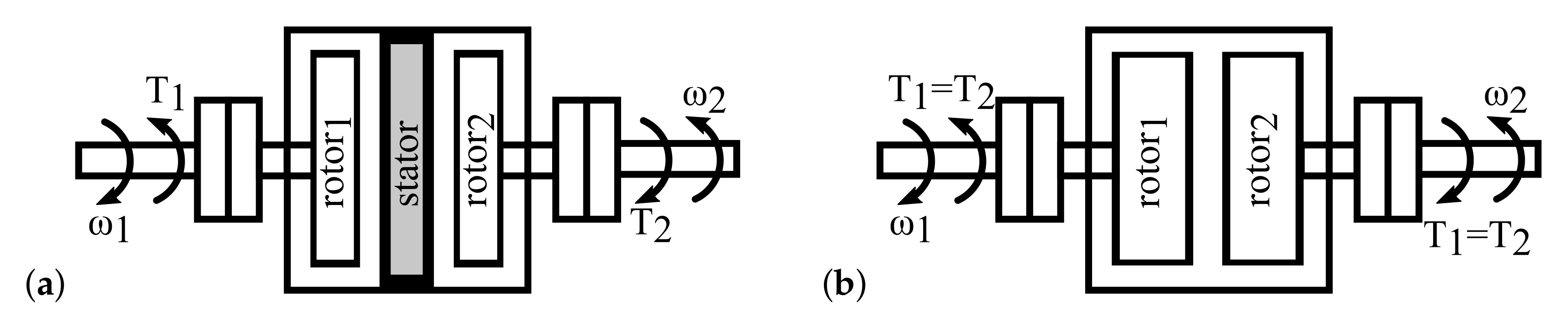
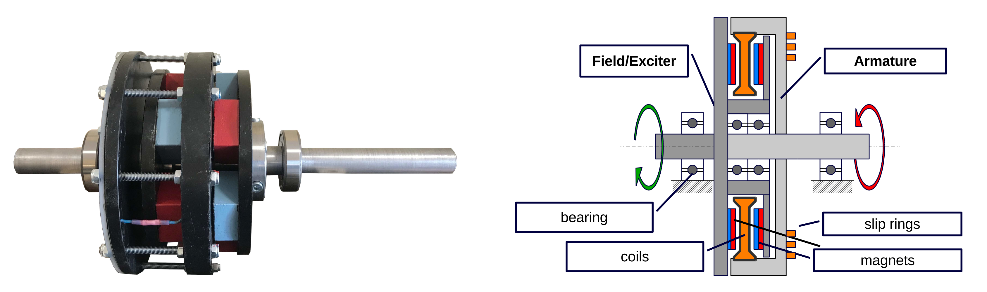
The objective of the research was to develop a novel axial flux permanent magnet generator that would take advantage of the dual rotor wind turbine concept. In typical permanent magnet generators, the field source, also known as the exciter, is the rotor and the armature is the stator. In the proposed construction, the field, as well as the armature, are both two independent rotors of the machine. That means they can revolve independently of each other and the stator. The axial flux machine type was selected for the generator design. This type of machine allows for relatively high torque-to-volume ratio. The main contribution of the research is the novel construction of the dual rotor axial flux permanent magnet generator.
The general approach in the machine design was based on the sizing equation [19]. The verification of the prototype design was carried out through FEM simulation in ANSYS Maxwell software, where the generator back EMF was calculated, and through the measurements where generator prototype power and efficiency was measured.
The design process was composed of three main steps:
  • Analytical calculation,
  • FEM simulation,
  • Prototype experimental measurements.
Figure 2 shows the iteration approach in the design process. The prototype measurements are used in order to verify the assumptions made during the analytical calculations.

2.1. Analytical Calculation of the Machine Dimensions

The general approach in machine design is based on the sizing equation. For the axial flux machine, this equation is defined as:
D o u t = P o u t π 2 k D k w 1 n s B m g A m η cos ϕ 3
where: D o u t ( m ) is the external diameter of the PM, P o u t ( W ) is the output power of the machine (mechanical power in the case of motor, electrical power in the case of generator), k w 1 is the winding factor for the fundamental component of the winding magnetomotive force (MMF), n s is the machine rotational velocity (in the case of the dual rotor machine, it is differential rotational velocity between two rotors), B m g ( T ) is the amplitude of the air gap flux density normal component, A m ( A / m ) is the amplitude of the linear current density, cos ϕ is the power factor of the machine, η is the efficiency of the machine and the k D is defined based on the ratio of the internal PM diameter D i n ( m ) to the external PM diameter D o u t ( m ) :
k d = D i n D o u t k D = 1 8 1 + k d 1 k d 2
As can be noticed, the power of the machine is dependent on the machine rotational velocity and the product of linear current density and air gap flux density, which determines the air gap tangential stress or the torque. For set rotational velocity, power is defined by the torque, which in turn is dependent on the machine external diameter cubed.
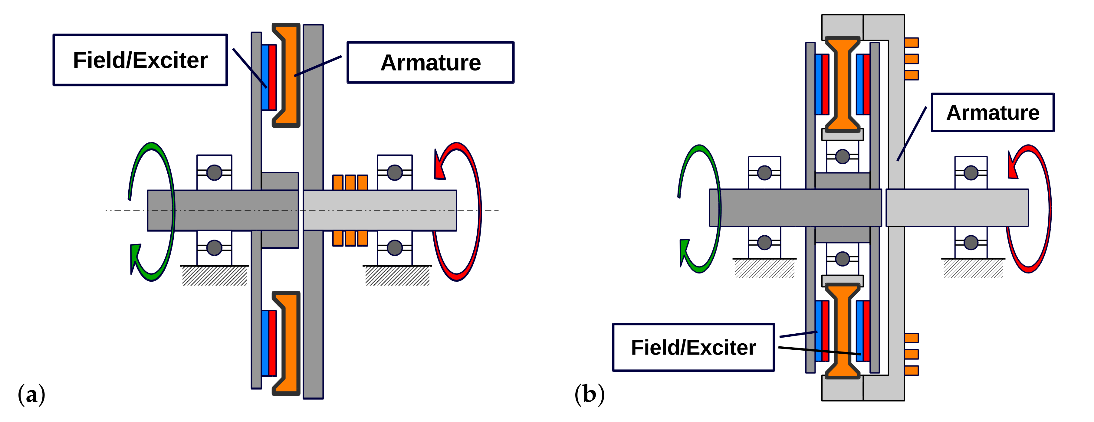
The axial flux machines are known for their large diameter in relation to machine length. Which makes them suitable for low speed, high torque solutions. In order to increase the power density of the proposed solution, an axial flux machine with counter-rotating field and coreless armature has been proposed. In the axial flux machine with a coreless armature and dual permanent magnet disc-shaped field, the exciter is usually made out of construction mild steel or carbon steel with permanent magnets glued to its surface. This carbon steel magnetic core has much lower relative magnetic permeability (40 to 100 times lower) than electrical or lamination steel. However, in a machine with a coreless armature, this does not affect the machine performance. This type of construction is very popular due to the fact that it is very easy to manufacture even without any advanced equipment. Because of the coreless armature, the power density is reduced. However, in axial flux machines, the power is proportional to its diameter cubed. In low power machines, even a small increase in the diameter can compensate for the lower power density of the coreless design. In addition, a dual PM exciter disc solution allows increasing the flux linkage of coreless armature machines. Figure 3 shows the single and dual exciter construction of the dual rotor axial flux machine.
In the sizing Equation (1), the rotational velocity ns is the relative velocity between the excitation and the armature. In the proposed solution of the machine with a rotating field and armature, each of these components will rotate in the opposite direction powered by a separate wind turbine. The resulting relative velocity will be the sum of the speed of the field and the armature in reference to the machine enclosure.
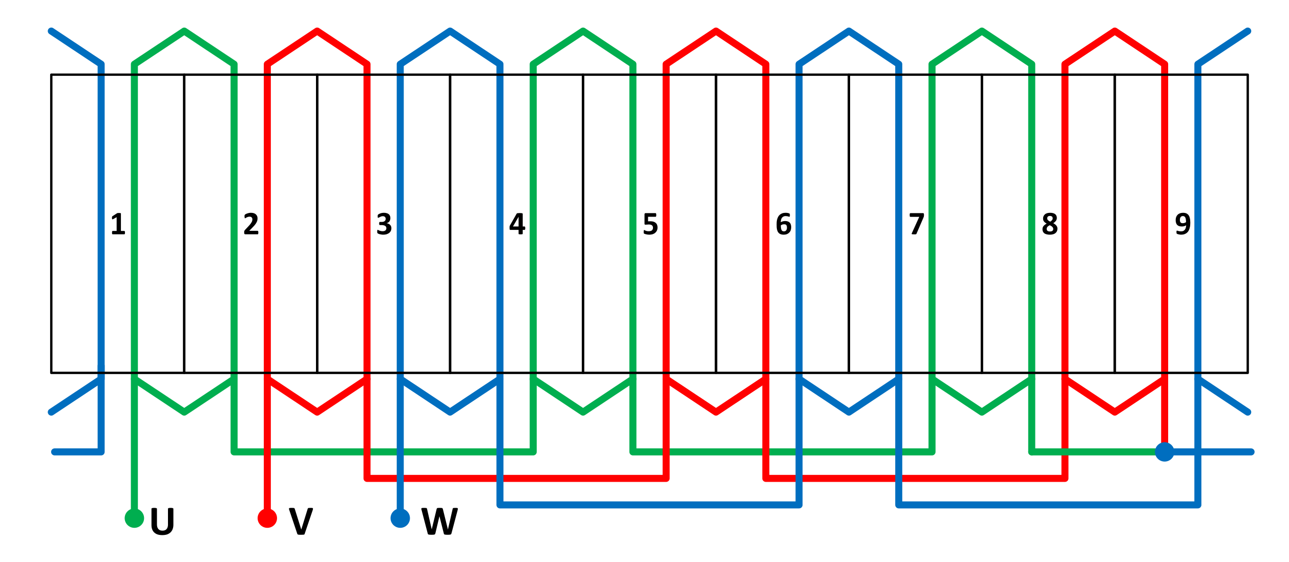
The machine three phase winding constructions consist of nine coils. Three coils are connected in series in each phase. The winding is a fractional slot winding or the tooth coil winding type where the number of slots per pole and per phase is 0.5. The number of winding turn per phase was calculated based on the machine flux linkage:
N s = ϵ · 2 · V 1 L N ω · k w 1 · ϕ ^ m
where ϵ is the ratio of machine phase-to-phase back EMF Ef to the fundamental component of machine voltage, ω ( r a d / s ) is the electrical rotational velocity ( ω = p ω m , where p is the number of pole pairs) and V 1 ( V ) is defined as:
ϵ = E f V 1
and for the generator 1.2 > ϵ > 0 . The ϕ ^ m 
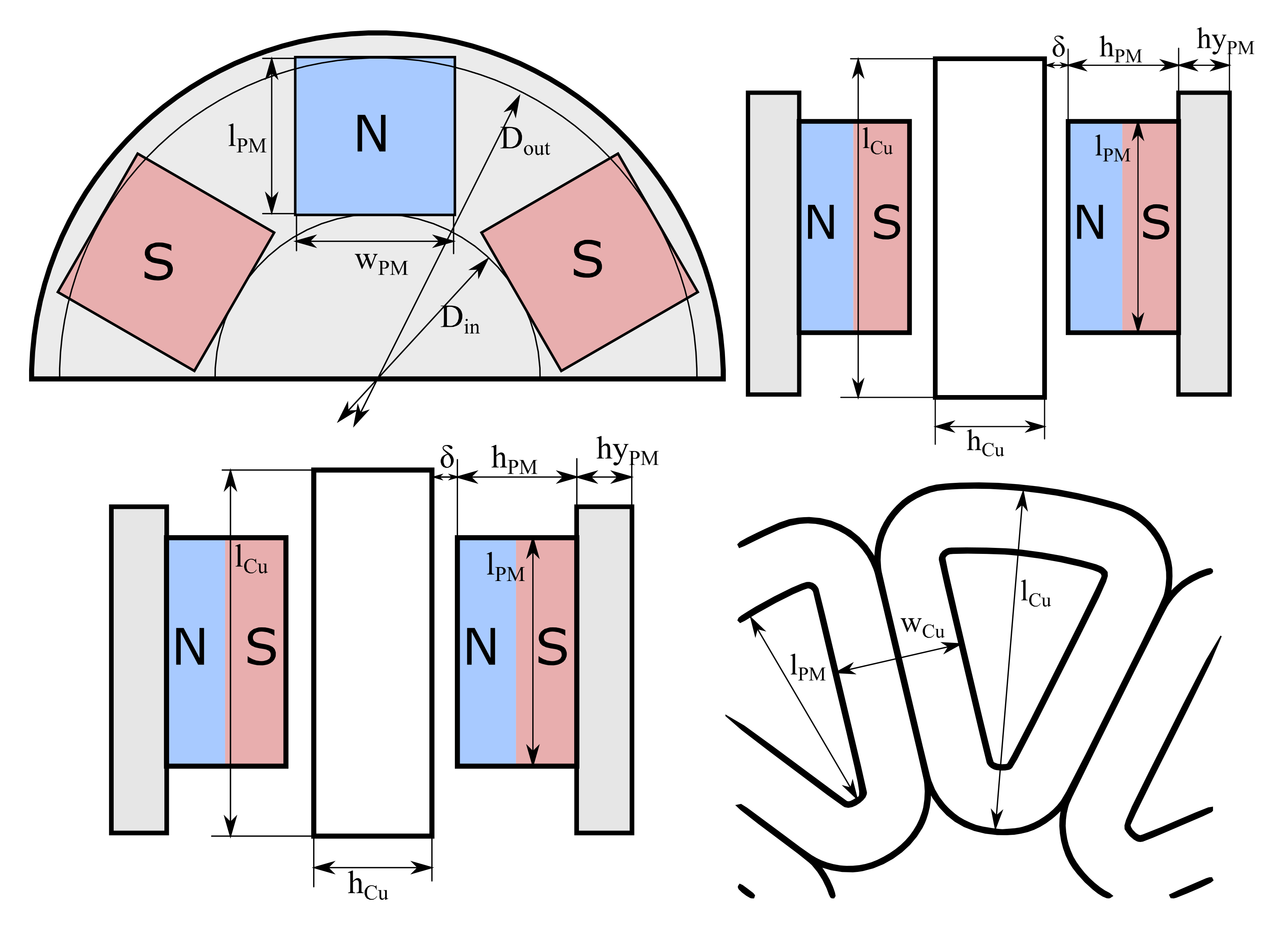
is the amplitude of flux linkage and is calculated based on the magnitude of air gap flux density, the slot pitch and the external and internal diameter of the machine:
ϕ ^ m = B m g · k B D o u t D i n 2 τ s
where τ s ( m ) is the slot pitch and k B 
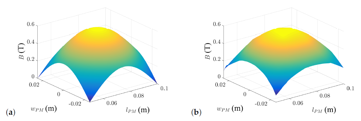
is the air gap flux density distribution factor as a ratio between the average and maximum value of the air gap flux density. The machine has coreless armature and relatively high value of PMs height in reference to pole pitch. Because of that, the air gap flux distribution along the width ( w P M ( m ) ) and the length ( l P M ( m ) ) of the PM is close to sinusoidal and can be defined as:
B δ w , l = B m g 2 sin l l P M π + sin w w P M π
Based on this, the air gap flux density distribution factor can be defined as:
k B = 2 π 2
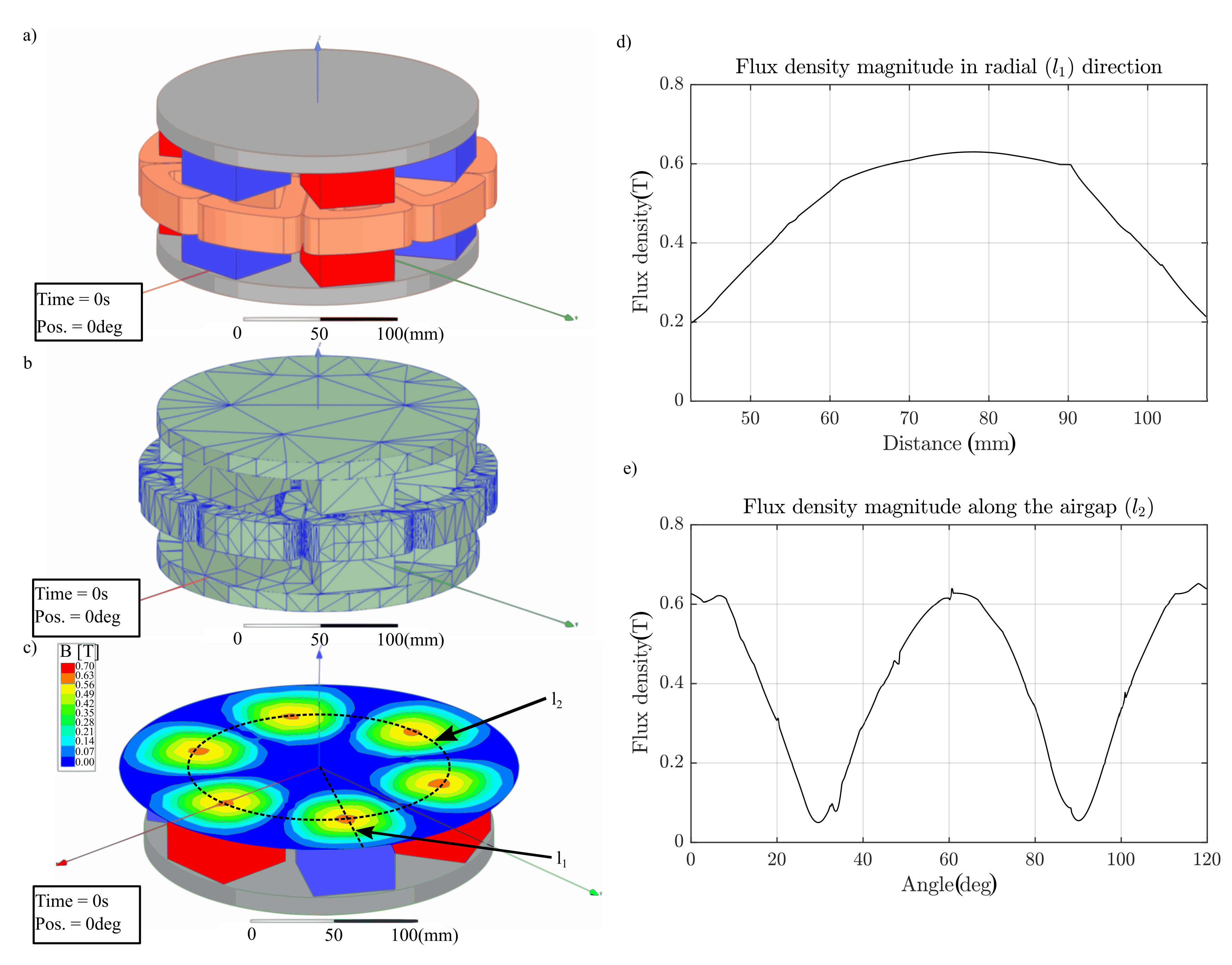
This coefficient value was later verified using FEM simulations. The expected distribution of the normal component of air gap flux density between two magnets in the coreless armature is presented in Figure 4.
The material used for the exciter rotor was construction milled steel S355 and the PM material is the N40. The general dimensions calculated during the design process are shown in Figure 5.
The magnetic or effective air gap length is defined as:
δ e f f = h C u + 2 δ
where δ ( m ) is construction/manufacturing air gap and h C u ( m ) is the armature height or the winding/slot height in the case of the coreless armature axial flux machine. Based on the maximum value of air gap flux density, the air gap length and the permanent magnet parameters at the operational temperature, the height of the PM is calculated:
h P M = δ e f f · μ P M · k P M 2 k P M B r P M B m g
where μ P M is the magnetic relative permeability of PM, k P M is the PM fill coefficient (defines the ratio between PM volume and PM specific material in that volume) and B r P M ( T ) is the remanence flux density of the PM. Figure 6 shows the winding construction of the designed machine.
Calculated machine dimensions are shown in Table 1.

2.2. FEM Analysis

The FEM analysis was used in order to verify the analytical calculation of the machine dimensions. In order to do that, two main tests were conducted:
  • The no load back EMF calculation,
  • The electromagnetic torque at nominal current calculation.
In order to perform the simulation, a model in ANSYS Maxwell environment was developed. Figure 7 shows the geometry of the machine in the FEM software as well as the mesh discretisation and an example of the simulation results. The basic process of the FEM simulation model development consists of the definition of geometry, the definition of materials and the definition of boundaries and excitations. Because of the coreless armature and material used for the PM rotor core (S355 construction steel) the relative magnetic permeability of μ r = 500 was used for the ferromagnetic PM rotor core during the simulations. A separate issue concerns the discretisation of the geometry also known as the mesh generation. In the Maxwell environment of the ANSYS software as in many other FEM simulations software, this step can be automated and left for the software default optimisation strategy based on the allowable error level of the performed simulation. It has to be considered in the design process that coreless armature of the machine creates a large air gap in reference to the armature length (in this case this length is understood as the length of the PM). This results in a decreased value of the average flux density of the flux linkage in the machine. In a typical machine with a small air gap length in reference to the length of the machine, the relation between the average and maximum flux density in the air gap for sinusoidal flux density distribution is defined as B a v g / B m g = 2 / π .
However, in the case of the coreless axial flux machine, this value is decreased and influenced by several factors like the shape of PM, the direction of magnetisation of PM, the ratio between the air gap length and the length of the machine and the MMF of the machine winding. Using FEM simulation and results presented in Figure 3, one can estimate the relationship between the average and maximum flux density to be B a v g / B m g 0.5 .
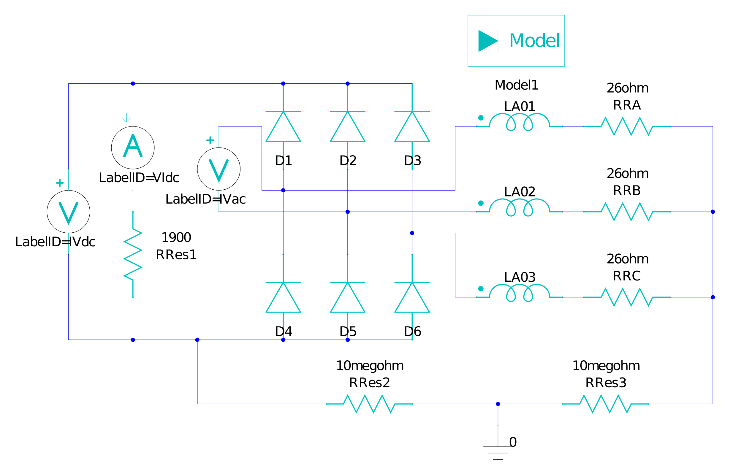
For the model verification, a transient simulation of the designed machine was conducted. For this simulation, a circuit model was defined in ANSYS Maxwell software. Figure 8 shows the circuit model. The winding resistances RRA, RRB and RRC have been calculated based on the design demotions of the machine coils. A series of simulations in which the machine velocity and the load resistance RRes1 were changing have been conducted. The differential velocity changed from 100 to 1000 rpm and the load resistance changed from 100 to 1900 ohms
The results of the simulations are shown in the next section of the paper, where they are compared with the measurements.

2.3. Experimental Verification of the Prototype Design

The generator prototype was constructed by the EMS Electric Motors Service Company, Poland. The key aspect in the prototype development was the mechanical construction of two rotating components of the generator. Sturdy construction was achieved using two points of contact between both rotors via the placement of the bearing between the inner and outer rotor. Figure 9 shows the internal structure of the prototype machine and transverse cross-section.
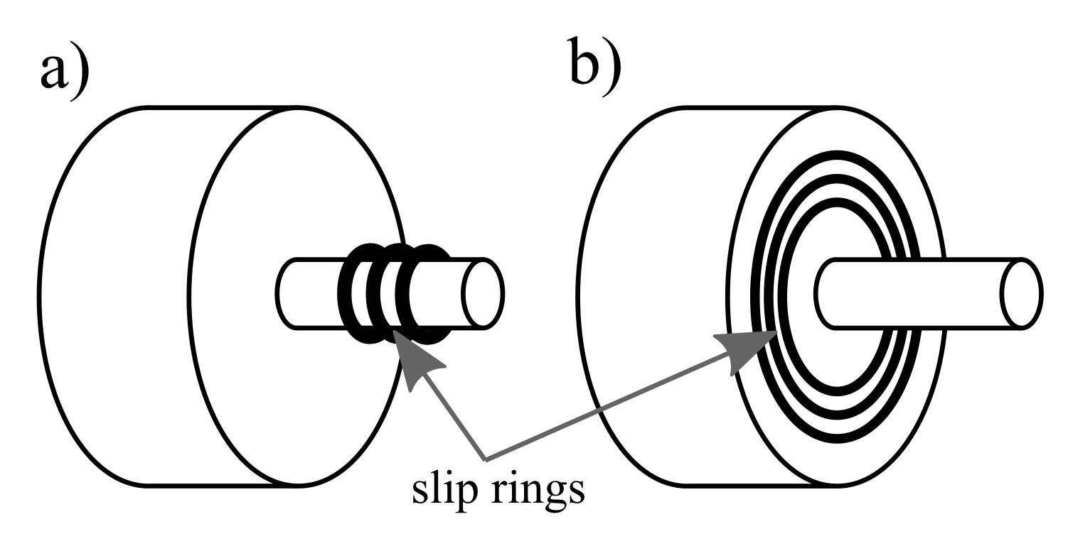
One of the key aspects apart from the mechanical decoupling between both rotors was the issue of the electrical energy transfer between the armature rotor and the terminal box of the generator. Generally in AC machines, a set of slip rings is used to supply or draw power from the rotating part of the machine, whether it is a synchronous machine with DC excitation winding on the rotor supplied via two slip rings or it is an ac induction machine with three phase wounded rotor and three slip rings. Usually, the slip rings are placed side by side on the shaft of the machine (Figure 10). In the case of the proposed dual rotor axial flux machine, the slip rings are in the form of concentric rings to which the brushes are spring-loaded parallel to the axis of the machine. The advantage of this approach is the smaller overall length of the machine, however, the disadvantage is the increase in the mechanical losses due to the friction in slip rings and much larger diameter of slip rings than in typical ac machines.
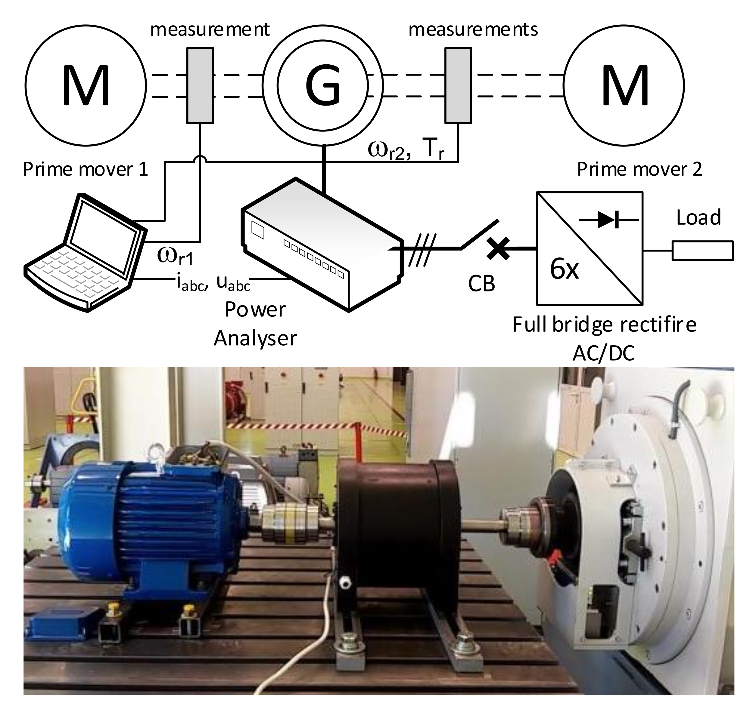
The experimental analysis of the prototype generator has been conducted in the laboratory. The dynamometer test stand equipped with HBM T40B type of torque sensor was used in the measurements. In addition, a second motor equipped with an encoder for speed measurement was used to move the second rotor of the generator. The electrical parameters of the generator were measured using a ZES LMG670 type of power analyser. Figure 11 shows the simplified measurement test stand schematic and dual-rotor generator test on the dynamometer test bench.
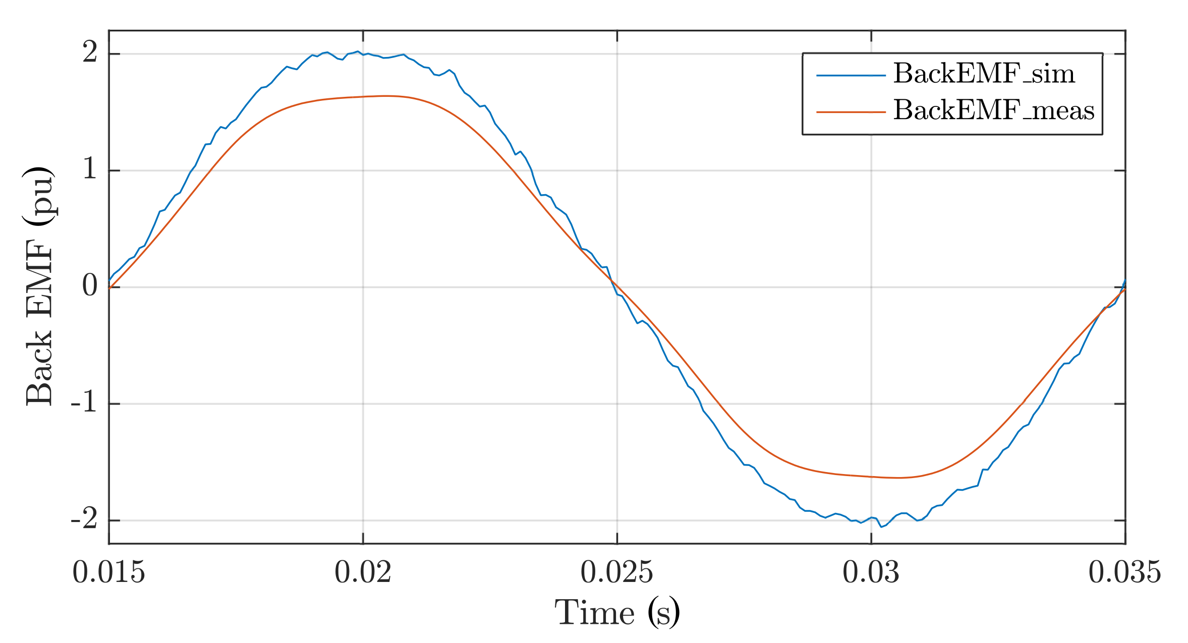
Conducted measurements included the back EMF waveform measurement of line-to-line voltage of the generator (
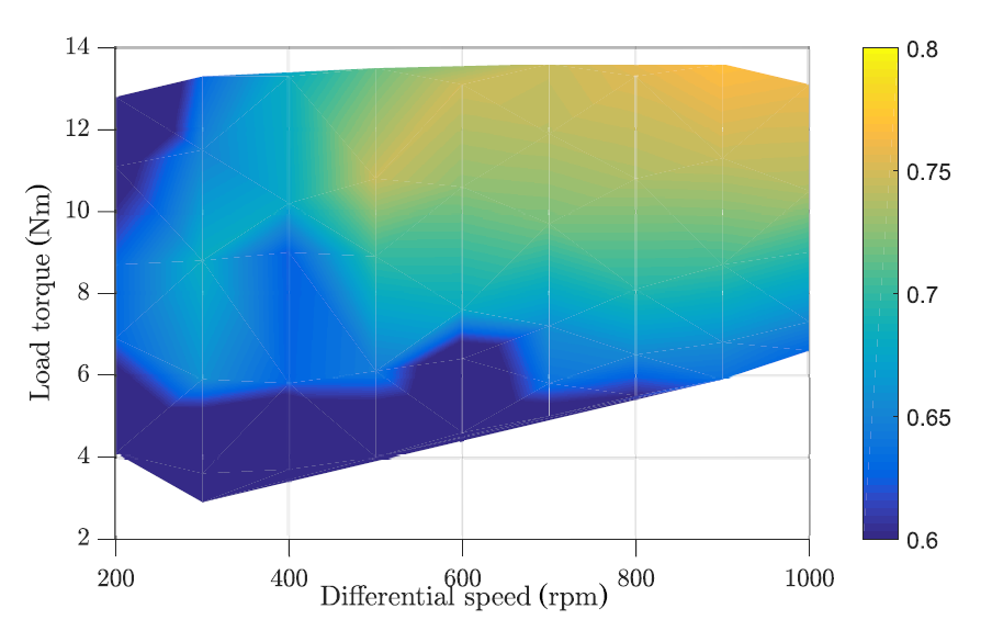
Figure 12). Also, the efficiency of the prototype generator was measured for selected differential speeds between the rotors and selected load conditions. Figure 13 shows the measured efficiency of the prototype generator.
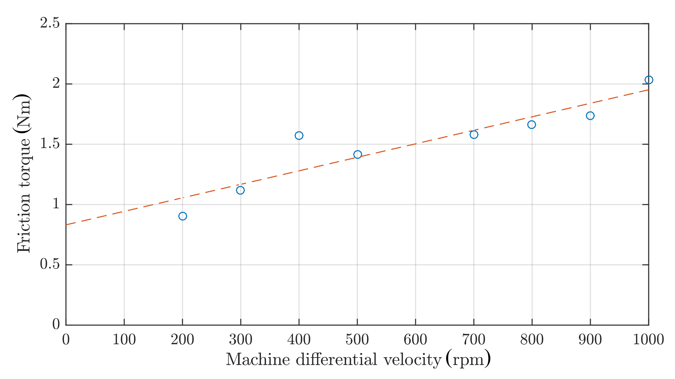
In order to compare the electromagnetic FEM simulations and measurements, mechanical losses had to be incorporated into the FEM results. The static and dynamic friction calculated based on the measurements in load and no load conditions for different relative rotational velocities torque has been added to the simulation. Figure 14 shows the friction torque in the function of differential speed.
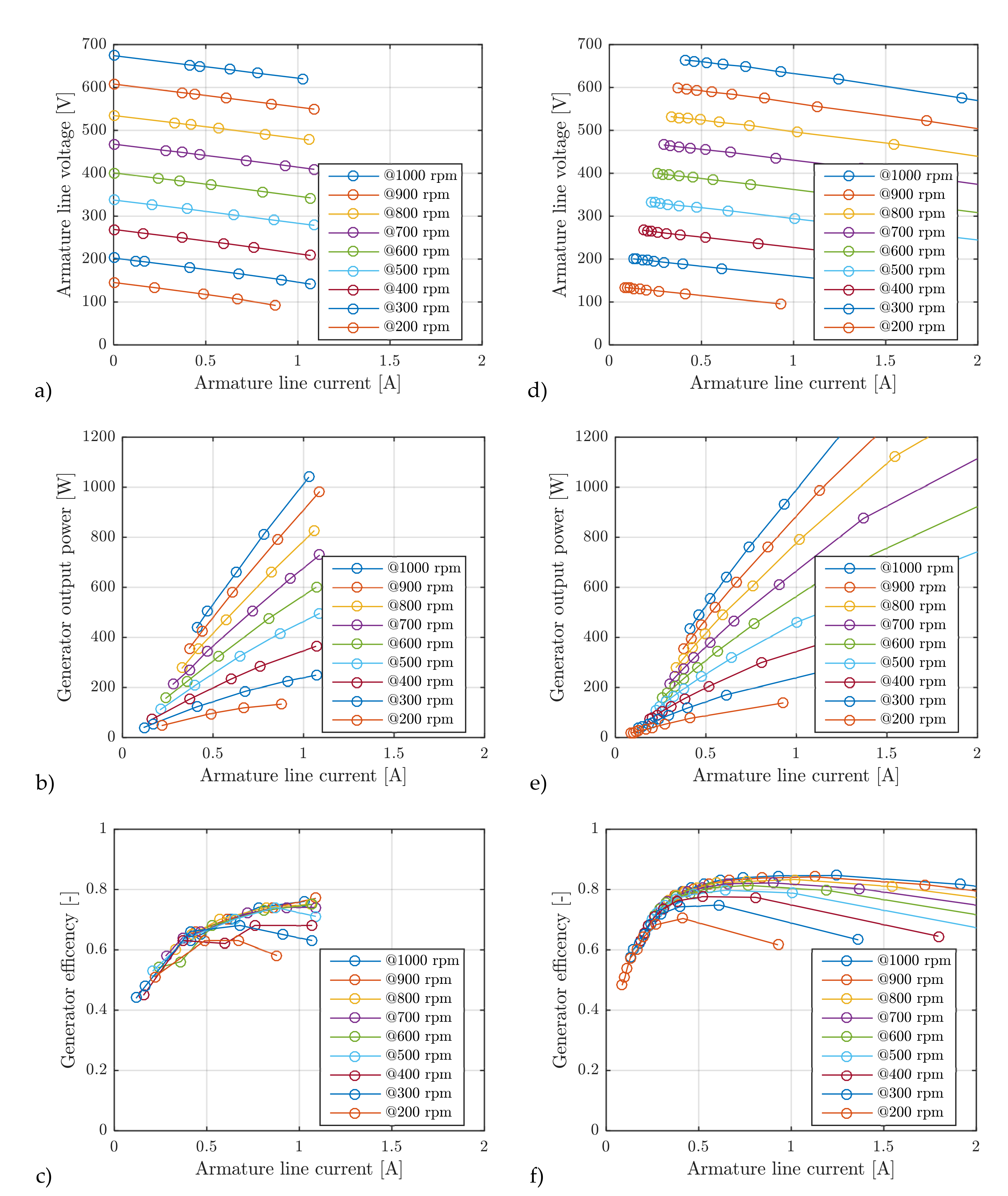
The results of FEM simulations and measurements are shown in Figure 12. The line-to-line voltage, output electrical power and the efficiency ware calculated from both measurements and simulations. The efficiency calculated from the FEM simulation included measured static and dynamic friction:
η = P e T e + D 1 · ω m + D 2 ω m
where T e is electromagnetic torque developed by the simulated machine, D 1 and D 2 represent the dynamic and static component of friction torque (Figure 14) and P e is the output electrical power of the generator.
The presented result of the simulation and measurements in Figure 12 and Figure 15 indicate a significant difference between the simulations and measurements. The higher calculated efficiency can be caused by both the higher value of induced EMF and also the omission of additional losses due to AC resistance and eddy currents in ferromagnetic construction elements of the machine. The lower value of induced EMF can be caused by:
  • Different PM parameters the assumed/selected in the calculations,
  • Different than designed coil dimensions/layout,
  • Additional leakage flux caused by the ferromagnetic components of the machine construction (shafts, bolts, etc.).

3. Conclusions

During the research, a dual rotor axial flux generator prototype was developed, constructed and tested. The unique mechanical construction of the generator allows for independent rotation of both the permanent magnet exciter and coreless armature. The proposed generator is indented for wind turbine operation reliability by eliminating the mechanical gearbox.
The obtained results of efficiency measurements shown in Figure 15 indicate that the generator’s efficiency is not very high. It can be assumed that this may be the result of a significant measuring error of the used torque meter because its measuring range was too large for the tested machine. The tests would have to be repeated on a smaller dynamometer. The torque meter used in the tests is the factory equipment of our 180 kW dynamometer and cannot be replaced with a smaller one. Measurements were made on a dynamometer with a K-T40B-002R-MF-S-M-DU2-0-S type flange torque sensor, ± 2000 Nm, accuracy 0.05%.
During the tests, attention was also paid to the occurring cogging torque between both rotors caused by ferromagnetic bolts holding the armature winding plate, which may impede the operation of a wind farm at lower wind speed. Therefore, a twin-rotor wind turbine was prepared for testing in the wind tunnel. The dual-rotor generator coupled with CRWT was shown in Figure 16.
For a quantitative assessment of prototype properties, measurements would have to be repeated on a more adequate dynamometer. However, the main objective of the research was the development of a novel structure of dual rotor axial flux PM generator, and this objective was reached. The further steps will include optimisation of the proposed structure and for that, more precise measurement equipment will have to be used.

Author Contributions

Conceptualization, F.K., K.B., and D.K.; methodology, F.K. and K.B.; software, F.K; validation, F.K., K.B., and D.K.; formal analysis, F.K., K.B., and D.K.; investigation, F.K., K.B; resources, F.K., K.B., and D.K.; writing original draft preparation, F.K.; writing review and editing, F.K. and D.K.; visualization, F.K., K.B.; supervision, F.K. and K.B.; project administration, K.B.; funding acquisition, K.B. All authors have read and agreed to the published version of the manuscript.

Funding

This research was funded by the Pomeranian Research and Development Projects of WFOŚiGW (ang. Voivodeship Fund for Environmental Protection and Water Management in Gdańsk, Poland), Grant acronym CRWT (counter-rotating wind turbine with dual rotor generator) RX-15/4/2017.

Acknowledgments

The tests were performed using equipment of LINTE^2 laboratory of the Gdańsk University of Technology, Poland.

Conflicts of Interest

The authors declare no conflict of interest. The funder has no role in the design of the study; in the collection, analyses, or interpretation of data; in the writing of the manuscript, or in the decision to publish the results.

References

  1. Newman, B.G. Multiple actuator-disc theory for wind turbines. J. Wind Eng. Ind. Aerodyn. 1986, 24, 215–225. [Google Scholar] [CrossRef]
  2. Vasel-Be-Hagh, A.; Archer, C.L. Wind farms with counter-rotating wind turbines. Sustain. Energy Technol. Assess. 2017, 24, 19–30. [Google Scholar] [CrossRef]
  3. Moghadassian, B.; Rosenberg, A.; Sharma, A. Numerical Investigation of Aerodynamic Performance and Loads of a Novel Dual Rotor Wind Turbine. Energies 2016, 9, 571. [Google Scholar] [CrossRef] [Green Version]
  4. Lipian, M.; Dobrev, I.; Karczewski, M.; Massouh, F.; Jozwik, K. Small wind turbine augmentation: Experimental investigations of shrouded- and twin-rotor wind turbine systems. Energy 2019, 186, 115855. [Google Scholar] [CrossRef] [Green Version]
  5. Schonball, W. Electric Generator Arrangement. U.S. Patent US3974396A, 10 August 1976. [Google Scholar]
  6. McCombs, J.C. Machine for Converting Wind Energy to Electrical Energy. U.S. Patent US US5506453A, 9 August 1996. [Google Scholar]
  7. Herzog, R.; Schaffarczyk, A.; Wacinski, A.; Zürcher, O. Performance and stability of a counter–rotating windmill using a planetary gearing: Measurements and Simulation. In Proceedings of the European Wind Energy Conference & Exhibition, Warsaw, Poland, 20–23 April 2010. [Google Scholar]
  8. Wacinski, A. Drive device for a windmill provided with two counter-rotative propellers. U.S. Patent US US7384239B2, 10 June 2008. [Google Scholar]
  9. Neagoe, M.; Saulescu, R.; Jaliu, C. Design and Simulation of a 1 DOF Planetary Speed Increaser for Counter-Rotating Wind Turbines with Counter-Rotating Electric Generators. Energies 2019, 12, 1754. [Google Scholar] [CrossRef] [Green Version]
  10. Gieras, J.F.; Wang, R.J.; Kamper, M.J. Axial Flux Permanent Magnet Brushless Machines, 2nd ed.; Springer: New York, NY, USA, 2008. [Google Scholar]
  11. Honsinger, V.B. Sizing Equations for Electrical Machinery. IEEE Trans. Energy Convers. 1987, EC-2, 116–121. [Google Scholar] [CrossRef]
  12. Huang, S.; Luo, J.; Leonardi, F.; Lipo, T.A. A general approach to sizing and power density equations for comparison of electrical machines. IEEE Trans. Ind. Appl. 1998, 34, 92–97. [Google Scholar] [CrossRef] [Green Version]
  13. Hosseini, S.; Agha-Mirsalim, M.; Mirzaei, M. Design, Prototyping, and Analysis of a Low Cost Axial-Flux Coreless Permanent-Magnet Generator. IEEE Trans. Magn. 2008, 44, 75–80. [Google Scholar] [CrossRef]
  14. Chalmers, B.; Spooner, E. An axial-flux permanent-magnet generator for a gearless wind energy system. IEEE Trans. Energy Convers. 1999, 14, 251–257. [Google Scholar] [CrossRef]
  15. Melcescu, L.; Tudorache, T.; Craiu, O.; Popescu, M. Finite element analysis of a wind generator with two counter-rotating rotors. In Proceedings of the 2017 International Conference on Optimization of Electrical and Electronic Equipment (OPTIM) 2017 Intl Aegean Conference on Electrical Machines and Power Electronics (ACEMP), Brasov, Romania, 25–27 May 2017; pp. 408–413. [Google Scholar] [CrossRef]
  16. Dranca, M.; Chirca, M.; Cosman, S.; Jurca, F.; Breban, S. Experimental validation of a permanent-magnet micro-wind turbine generator with counter rotating rotors. In Proceedings of the 2017 International Conference on ENERGY and ENVIRONMENT (CIEM), Bucharest, Romania, 19–20 October 2017; pp. 335–338. [Google Scholar] [CrossRef]
  17. Xu, P.; Shi, K.; Sun, Y.; Zhu, H. Analytical Model of a Dual Rotor Radial Flux Wind Generator Using Ferrite Magnets. Energies 2016, 9, 672. [Google Scholar] [CrossRef] [Green Version]
  18. Xu, P.F.; Liu, X.X.; Shi, K.; Du, Y. Design of Dual-Rotor Radial Flux Permanent-Magnet Generator for Wind Power Applications. Appl. Mech. Mater. 2013, 416–417, 9–14. [Google Scholar] [CrossRef]
  19. Pyrhonen, J.; Jokinen, T.; Hrabovcova, V. Design of Rotating Electrical Machines; John Wiley & Sons, Inc.: Hoboken, NJ, USA, 2007. [Google Scholar]
Figure 1. The general structure of the dual rotor machine: (a) machine with two rotors and a stator; (b) machine with two rotors and no stator.
Energies 13 02833 g001
Figure 2. The general approach during the prototype design process.
Energies 13 02833 g002
Figure 3. Dual rotor axial flux machine solutions: (a) single permanent magnet (PM) exciter disk and single armature disk; (b) two PM exciter disks and single armature disk.
Energies 13 02833 g003
Figure 4. Normal component air gap flux distribution from two permanent magnets in the middle of the coreless armature, (a) calculated value based on the assumption expressed by Equation (6); (b) finite element method (FEM) simulation result.
Energies 13 02833 g004
Figure 5. Machine dimensions calculated during the design process.
Energies 13 02833 g005
Figure 6. Concentrated winding of the designed machine.
Energies 13 02833 g006
Figure 7. FEM analysis of designed machine: (a) geometry view in Ansys Maxwell 3D, (b) finite elements discretisation of the geometry, (c) example of the results—flux density in the middle of the coreless armature, (d) flux density in the radial direction (along l 1 ), (e) flux density along the air gap at the middle of PM (along l 2 ).
Energies 13 02833 g007
Figure 8. FEM analysis circuit model for the transient simulations.
Energies 13 02833 g008
Figure 9. The internal structure of the prototype axial flux generator (left), a transversal cross-section (right).
Energies 13 02833 g009
Figure 10. Three phase slip rings configuration: (a) typical machine, (b) concentric slip ring configuration used in prototype generator.
Energies 13 02833 g010
Figure 11. Dynamometer test bench configuration during the measurements.
Energies 13 02833 g011
Figure 12. Generator back electromotive force (EMF) FEM simulation and measurements.
Energies 13 02833 g012
Figure 13. Prototype generator efficiency diagram from measurements at the dynamometer stand.
Energies 13 02833 g013
Figure 14. Designed machine friction torque in the function of relative rotational velocity.
Energies 13 02833 g014
Figure 15. FEM simulation and measurements results: (a) measured machine voltage, (b) measured machine output electrical power, (c) measured machine efficiency, (d) simulated machine voltage, (e) simulated machine output electrical power, (f) simulated machine efficiency.
Energies 13 02833 g015
Figure 16. Permanent-magnet dual-rotor generator coupled with counter-rotating wind turbine for efficiency wind research: real photo (a), virtual model (b).
Energies 13 02833 g016
Table 1. Calculated dimensions of the designed generator.
ParameterValueDescription
D o u t 200 mmexternal diameter
D i n 100internal diameter
δ 2 mmmechanical air gap
h P M 25 mmPM height
l P M 50 mmPM length
w P M 50 mmPM width
h y P M 12 mmPM rotor yoke height
l C U 80 mmsingle coil length
h C U 25 mmcoil height
w C U 30 mm”slot“ width
N s 1815number of armature winding turns
D d s 0.55 mmdiameter of armature winding wire

