Wireless Power Transfer for Implanted Medical Application: A Review


Abstract
1. Introduction
2. Nerve Stimulation
2.1. Deep Brain Stimulation
- (1)
- Convenience enhancement: Analyzing deep brain activities can be easier than before. With two transmission strategies, namely a wearable energy supplier or a recharge cage, it can allow the object to move freely during the charging period.
- (2)
- Potential for full implantation: Fully embedded devices have become the mainstream of the brain research field. Due to the difficulties in plug-in charging and minimization, WPT offers an efficient alternative for practical applications.
- (3)
- Possibility for stretchable implants: Flexibility of coil structure ensures the possibility of applying the stretchable optogenetics system [18].
- (1)
- Minimization difficulty: In order to protect other parts of the brain, the overall size of the implants needs to be small enough. Aside from difficulties in minimizing the functional parts of devices, materials and techniques for downsizing powering sections are still under development.
- (2)
- (3)
- Complicated transmitting gap characteristics: It is difficult to align the results of simulations and in vitro and in vivo tests, since the characteristics of biological tissues are hard to determine, especially when these characteristics vary between individuals.
- (1)
- Development of new materials and energy storage techniques will accelerate WPT application in implants: Nano super-capacitors and GaN-based capacitors can be used to store energy from a harvesting source, such as piezoelectric nanowires [23].
- (2)
- Combination of wireless communication and power transfer: Brain implants generally aim for activity analysis, and the combination of two main functions could downsize these devices.
- (3)
- Some new topologies of WPT can be adopted in deep brain therapy, which could significantly improve the PTE and the output power, as well as the therapy effect.
2.2. Peripheral Stimulation
2.2.1. Vagus Nerve Stimulation

| Category | Frequency | Input 1 | Output 2 | Efficiency 3 | Transmitting Distance | Transmitting Coil | Receiving Coil | Material/Encapsulation 4 | Media | ||
|---|---|---|---|---|---|---|---|---|---|---|---|
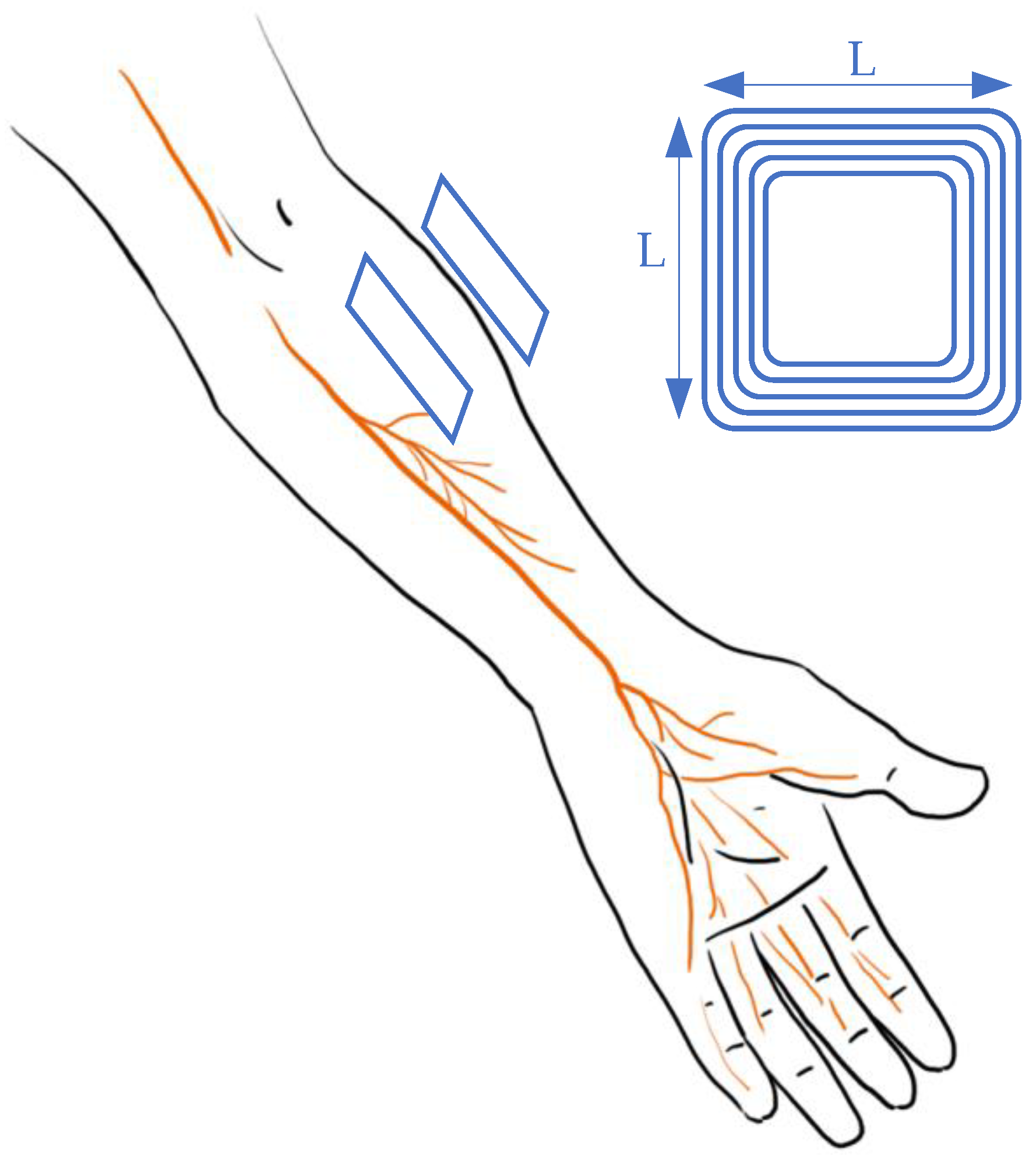
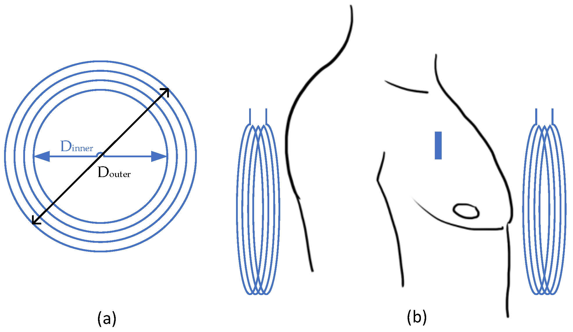
| Cortical [25] | 907.5 MHz | 20.1 mW | 15.6 µW | ~0.04% | 16 mm = 11benearth+ 5air | Annulus: Douter = 41.3 mm Dinner = 10 mm | Cubic: L = 1 mm | PDMS | Head equivalent phantom | ||
| Cortical [25] | ISM band | 26.8 mW | 15.6 µW | ~0.05% | 32 mm = 20bone+5fat+2skin+5air | Annulus: Douter = 41.3 mm Dinner = 10 mm | Cubic: L = 1 mm | PDMS | Porcine measurement | ||
| Cortical [25] | 907.5 MHz | ~29 mW | 118 µW | ~0.4% | 16 mm = 11benearth+ 5air | Annulus: Douter = 41.3 mm Dinner = 10 mm | Planar square: L = 6.5 mm | PDMS | Man’s Head model | ||
| Cortical [15] | 400 MHz | 19 mW (SAR1g), 82 mW (SAR10g) | 100 mW | 0.1% | 15 mm = 12benearth+ 3air | Annulus: Dmean = 12 mm | Approx. cubic L ~ 1 mm | medical grade silicone & Parylene C | Porcine tissue & Mice back | ||
| Optogenetic [26] | 13.56 MHz | N/A | N/A | 0.56% | Movable 6 | Cuboid: 40 cm × 40 cm × 20 cm | Planar square: L = 10 mm | medical grade silicone & Parylene C | Porcine tissue & Mice back | ||
| Optogenetic [27] | 7.2 MHz | N/A | N/A | 3.16% | 15 mm = 12benearth+ 3air | Planar square: L = 10.5 mm | Planar square: L = 10.5 mm | medical grade silicone & Parylene C | Porcine tissue & Mice back | ||
| Cortical [14] | 400 MHz | 19 mW (SAR1g), 82 mW (SAR10g) | 100 mW | 0.1% | 15 mm = 12benearth+ 3air | Annulus: Dmean = 12 mm | Approx. cubic L ~ 1 mm | medical grade silicone & Parylene C | Porcine tissue & Mice back | ||
| Cortical [28] | 400 MHz | 18 mW | 57 µW | 0.32% | 10 mm | Annulus: Douter = 18 mm Dinner = 12 mm | Approx. cubic L ~ 1 mm | medical grade silicone & Parylene C | Man’s Head model & CSF | ||
| Deep brain [7] | 403 MHz | ~99 mW | 10.52 mW | 10.62% 7 | 5 mm = 3benearth+ 2skin | Annulus: Dmean = 19.86 mm | Annulus: Dmean = 15.94 mm | N/A | N/A | ||
| Deep brain [26] | 13.56 MHz | 0.5 A | 8.5 mW | 0.56% | Movable 6 | Cuboid: 40 cm × 4 0 cm × 20 cm | Approx. cubic L ~ 1 cm | LTPS TFTs | 1X PBS | ||
| General [29] | 120 kHz | 9 V | 16V/250 mW | N/A | Movable 6 | Annulus: Douter = 44 mm Dinner = 8 mm Thickness = 1 mm | Annulus: Douter = 22 mm Dinner = 18 mm Thickness = 0.5 mm | N/A | Air | ||
| General 5 [30] | 160 MHz | N/A | 60 mW | 60% 8 | Movable 6 | Annulus: Douter = 35 mm Dinner = 34.4 mm | Annulus: Douter = 15 mm Dinner = 14.8 mm | Annulus: Douter = 10 mm Dinner = 9.8 mm | N/A | Air | |
| General [31] | 13.56 MHz | 12 W | 50 mW/mm2 | N/A | Up to 30 cm | Two Planar squares: L = 30cm Distance = 9 cm | Annulus: Douter = 9.8 mm Thickness = 18 µm | Uniform bilayer of parylene; PDMS | In vivo test (mice) | ||
2.2.2. Retinal Nerve Stimulation
| Category | Frequency | Input 1 | Output 2 | Efficiency 3 | Transmitting Distance | Transmitting Coil | Receiving Coil | Material/Encapsulation 4 | Media | ||
|---|---|---|---|---|---|---|---|---|---|---|---|
| Subretinal [40,41] | 125 kHz | ~100 mW | 0.76 mC/cm2 for 16 pulses/s | N/A | 20 mm | Annulus: Douter = 41.3 mm Dinner = 33.7 mm | Annulus: Douter = 10.3 mm Dinner = 8.3 mm | Flexible polyimi-de substrate & Silicon | Air & phosphate buffered saline solution & minipig | ||
| Subretinal [36,37,39] | 125 kHz | ±2.5 V | N/A | N/A | 30 mm | Annulus: Dmean = 19 mm | Spherical D = 19 mm T = 2 mm | Polydimethylsiloxane (PDMS) & Titanium | Air & phosphate buffered saline solution & minipig | ||
| Subretinal [35] | 160 MHz | N/A | 320 µW | N/A | 1 cm | Dmean = 60 mm 4 windings | Tot. Length = 100 m 100 windings | LTPS TFTs | 1X PBS | ||
| General [28] | 1 MHz | 9V | 16V/250 mW | N/A | 7 mm | Annulus: Douter = 44 mm Dinner = 8 mm Thickness = 1 mm | Annulus: Douter = 22 mm Dinner = 18 mm Thickness = 0.5 mm | N/A | Air | ||
| General 5 [29] | N/A | N/A | 60 mW | 60% | 7 mm | Annulus: Douter = 35 mm Dinner = 34.4 mm | Annulus: Douter = 15 mm Dinner = 14.8 mm | Annulus: Douter = 10 mm Dinner = 9.8 mm | N/A | Air | |
| General 5 [43] | 10 MHz | N/A | 25 mW | 36% | 21 (outside)+4 (inside) mm | Annulus: Douter = 42 mm Dinner = 34.4 mm | Annulus: Douter = 20 mm Dinner = 14.8 mm | Annulus: Douter = 10 mm Dinner = 9.8 mm | N/A | Air & saline | |
- (1)
- Minimization can be maintained with the flexible design of coils, while the wireless system obtains the functions of both power transfer and data telemetry;
- (2)
- The duration can be extended with the current photo-sensing circuit by the consistent power input;
- (3)
- Safety is guaranteed with the hermetic design and biocompatible materials.
- (1)
- Difficult implantation surgery: The non-planar structures of the target organs indicate a possible bending of receiving antenna, which would lead to relatively low power transfer efficiency.
- (2)
- Misalignment concerns: For devices designed to recover vision, it is hard to ensure alignment due to the 360° rotation ability of eyeballs, as the primary coil is fixed on wearable glasses while the receiving antenna is implanted inside the body. However, symmetry can be maintained with a secondary coil located with a certain degree and spot, while the regained vision is limited.
- (3)
- Change in transmission gap: Subretinal implantation is adopted for the majority of devices, as this ab externo surgery obtains a minimally invasive influence. However, the structure and composite of the retina could change with external impacts and age, which would lead to unexpected changes in electromagnetic permittivity and permeability.
- (1)
- Alignment improvement: Techniques with a high tolerance for misalignment and rotation will be developed. A combination of different coils to replace a singular receiver might be adopted. The strategies are also requested to maintain the low hazardousness and high convenience.
- (2)
- Self-powered design: Reuse the received light to power up the system.
- (3)
- Minimization of implanted electrodes: To increase the preciseness of stimulation and data analysis, the number of electrodes would increase under the constraints of mass and size.
2.2.3. Cochlear Nerve Stimulation
2.3. Spinal Stimulation
3. Assistant Devices
- (1)
- Effective energy supply: The fixed location and neglectable movement of implanted coil curtail the necessity of misalignment mitigation strategies. This would also escalate the PTE.
- (2)
- Large demand: Pacemakers consume considerable energy comparing to other implanted devices. As a consequence, invasive energy supply techniques are demanding.
- (3)
- High flexibility in coil design: As the coils can be detached from the major system, the space for receiving coil increases and can be applied for complex coil design or combination.
- (1)
- Varied transmitting distances among individuals: The thickness of chests for different people can affect the promotion of implanted WPT.
- (2)
- Safety concerns led by additional wire: As extra wires might be used to transmit the current to the pacers, the further induced effects [57] should be taken into consideration.
- (3)
- Health impacts due to long-term exposure to radiation: Radiation can influence the human body directly on DNA, genes, and protein. For pacemakers, the effect of heart attack due to the degradation of protein [67] should be considered.
- (1)
- Innovation in compensation topologies, such as LCC-C, LCL [68];
- (2)
- Adding ferrite cores to wireless links to intensify the electromagnetic field for high PTE;
- (3)
- Accurate numerical evaluation of SAR and thermal effects through simulation human body models [69].
| Category | Frequency | Output | Efficiency | Transmitting Distance 1 | Transmitting Coils 2 | Receiving Coils 3 | Encapsulation | Media | Safety Parameters 4 |
|---|---|---|---|---|---|---|---|---|---|
| Separated [66] | 160 kHz | 5 W | 88% | 0–10 cm | 2 planar spiral coils: n = 25, Δd = 190 mm, Douter = 280 mm, Dinner = 190 mm, 16 ferrite bars per coil | 2 planar spiral coils: n = 13, Δd = 5 mm, Douter = 50 mm | Titanium case | Male mannequin | 2 W/kg SAR (IEEE) |
| Combined [70] | 20 kHz | 500 mW | 77% | 8 mm = 3 + 2 + 3 | A planar spiral coil: n = 29, 18 AWG, Douter = 70 mm | A planar spiral coil: n = 39, 24 AWG, Douter = 46 mm | Titanium case Unipolar lead | Pork (3 mm air+3 mm skin+2 mm fat) | 2.7 V/m (ICNIRP) |
| General [68,71] | 300 kHz | 3.07 W * | 78% * | 8 mm = 1 + 2 + 5 | Planar helical coil with ferrite film, n = 13, 58×48 mm2, Copper strand (160 leads, D = 0.1 mm) Δhfilm = 0.29 mm | Planar helical coil with ferrite film: n = 9, 44.5 × 30.5 mm2, Δhfilm = 0.29 mm Flexible printed circuit | Titanium alloy material TC4 | Pork (1 mm pig skin +2 mm pig fat+ 5 mm pig lean) | 2.89 W/kg psSAR (IEEE) 4.22 °C increase |
| Separated [64,69] * | 300 kHz | 1 W | 80% | 10 mm | A planar spiral coil: 22 AWG, n = 10 Dinner = 36.6 mm | A planar spiral coil: 22 AWG, n = 4(SP), Douter = 35.4 mm | Titanium case | Air; saline solution | 2 W/kg SAR (IEEE) |
| Separated [64,69] * | 13.56 MHz | 1 W | 80% | 10 mm | A planar spiral coil: 22 AWG, n = 4 (SS), Dinner = 36.6 mm | A planar spiral coil: 22 AWG, n = 2 (SS), Douter = 35.4 mm | Titanium case | Air; saline solution | 2 W/kg SAR (IEEE) |
| Combined [72] | 13.56 MHz | 200 μW | 6.0% | 20–30 mm * | A planar spiral coil: n = 18, 23 AWG, Douter = 40 mm, Dinner = 10 mm | A planar spiral coil: n = 4, 30 AWG, Douter = 5 mm, Dinner = 1 mm | Titanium case | Euthanized pig | 2 W/kg SAR (IEEE) |
| Combined [73] | 198 MHz | 300 mW | NA | 200–300 mm * | 2 octagonal coils fabricated on one PCB board: n = 4, n = 3, Douter = 160 mm | A planar square coil: n = 6, 22 AWG, L = 4.9 mm | Titanium case | Ex vivo Langendorff heart models | NA |
4. Movable Implants
4.1. Gastrointestinal Endoscopy
- (1)
- The high design flexibility of power receiver: As the robotics may obtain different functions, the outlook and inside mechanical structures are various. WPT provides the opportunities for changing the receiving coil with relatively low ramifications on efficiency when compared to other power supply techniques.
- (2)
- Guarantee of sufficient power load: The power input can vary within the restriction of IEEE SAR standards, so the power output can be ensured even with unanticipated load variation. Additionally, a ferrite core can be added to intensify effective magnetic flux.
- (3)
- Potential on combined function: As the coils can transfer both energy and information, the implanted robotics capsules can deliver its location for positioning. This function would be helpful for fast charging and device location [86].
- (1)
- Low power transfer efficiency: As the robotic capsules obtain mechanical missions, the misalignment and rotation of receiving coils can be expected. Under this situation, the electromagnetic field leakage of the primary coil is relatively high.
- (2)
- Hard to be popularized: Transmitting conditions can vary with individual conditions, such as gender, nationality, age, obesity rate, etc. Although in vivo tests can illustrate a sufficient power output, real performances cannot be guaranteed.
- (3)
- Safety concerns led by information leakage: Due to immature encryption technologies, the leakage of operation frequency could result in a safety issue.
- (1)
- Redesigning wireless link to obtain the high tolerance of misalignment;
- (2)
- Current research emphasis is on the numerical or in vitro analysis and improvement, while these limited studies have demonstrated differences among results from these analyses and in vivo test [87];
- (3)
- Adding ferrite core with the high permeability to increase power received.
| Category | Frequency | Output | Efficiency | Transmitting Distance 1 | Transmitting Coils 2 | Receiving Coils 3 | Media 4 | ||||||||
|---|---|---|---|---|---|---|---|---|---|---|---|---|---|---|---|
| Helmholts [88] | 400 kHz | 790 mW | 3.00% | 310 mm * | Two octagonal coils: n = 13, Δd = 330 mm, Louter = 690 mm, Linner = 620 mm | Dmean = 10 mm, ferrite core: 6.6 mm × 6.6 mm × 5.5 mm | Air | ||||||||
| Charging system [77] | 13.56 MHz | 24 mW | 3.04% | 1000 mm | Powering group: 3 × 3, Δd = 1000 mm, Dmean = 480 mm | Dmean = 11 mm | Air | ||||||||
| Transmitting coil: 310 mm × 210 mm | |||||||||||||||
| Solenoid [89] | 164.7 MHz | 26 mW | 0.02% | 70 mm | Power coil: Dmean = 80 mm, n = 1 | Receiving coil: Dmean = 9 mm | Pork chops | ||||||||
| Transmitting coil: Dmean = 80 mm, n = 9.5 | Load coil: Dmean = 8 mm | ||||||||||||||
| Helmholtz [90] | 218 kHz | 600 mW | 2.00% | 250 mm * | Dmean = 500 mm | Dmean = 14 mm | Pig intestine | ||||||||
| Solenoids [91] | 220 kHz | 750 mW | 3.55% | 345 mm * | Two helical coils: n = 28, Δd = 345 mm, Dmean = 690 mm | Cube: 9.5 mm × 9.4 mm × 10.1 mm, ferrite core: 6.5 mm3 | Air | ||||||||
| Helmholtz [92] | 246 kHz | 534 mW | 4.90% | 200 mm * | D = 400 mm n = 14 | D = 400 mm n = 7 | Air | 3D orthogonal coil | Dy = 11.5 | Dy = 11.5 | Dz = 11.5 | Air | |||
| Δd = 150 mm | Δd = 150 mm | N = 150 | N = 142 | N = 135 | |||||||||||
| Helmholtz [78] | 250 kHz | 570 mW | 5.40% | 175 mm * | D = 350 mm n = 96 | D = 350 mm n = 32 | Air | D = 350 mm n = 96 | Receiving coil | Dx = 9.5 | Dy = 10.5 | Dz = 11.5 | Air | ||
| N = 140 | N = 142 | N = 141 | |||||||||||||
| Δd = 196.9 mm | Δd = 131.3 mm | Air | Load coil | Dx = 9.5 | Dy = 10.5 | Dz = 11.5 | |||||||||
| N = 3 | N = 3 | N = 3 | |||||||||||||
| Helmholtz [79] | 250 kHz | 758 mW | 8.21% | 175 mm * | D = 350 mm n = 96 | D = 350 mm n = 64 | Pork chops | Receiving coil | Dx = 9.5 | Dy = 10.5 | Dz = 11.5 | Air | |||
| N = 140 | N = 142 | N = 141 | |||||||||||||
| Δd = 140 mm | Δd = 140 mm | Load coil | Dx = 9.5 | Dy = 10.5 | Dz = 11.5 | ||||||||||
| N = 3 | N = 3 | N = 3 | |||||||||||||
| Solenoids [93] | 218 kHz | 500 mW | 4.08% | 200 mm * | Two layers pair of coils: n = 26, Δd = 200 mm, Dmean = 400 mm | Dmean = 13 mm, 12 strands, AWG44 MnZn ferrite R10K core: l = 6.3 mm | Air | ||||||||
4.2. Drug Delivery System
4.2.1. Active Devices
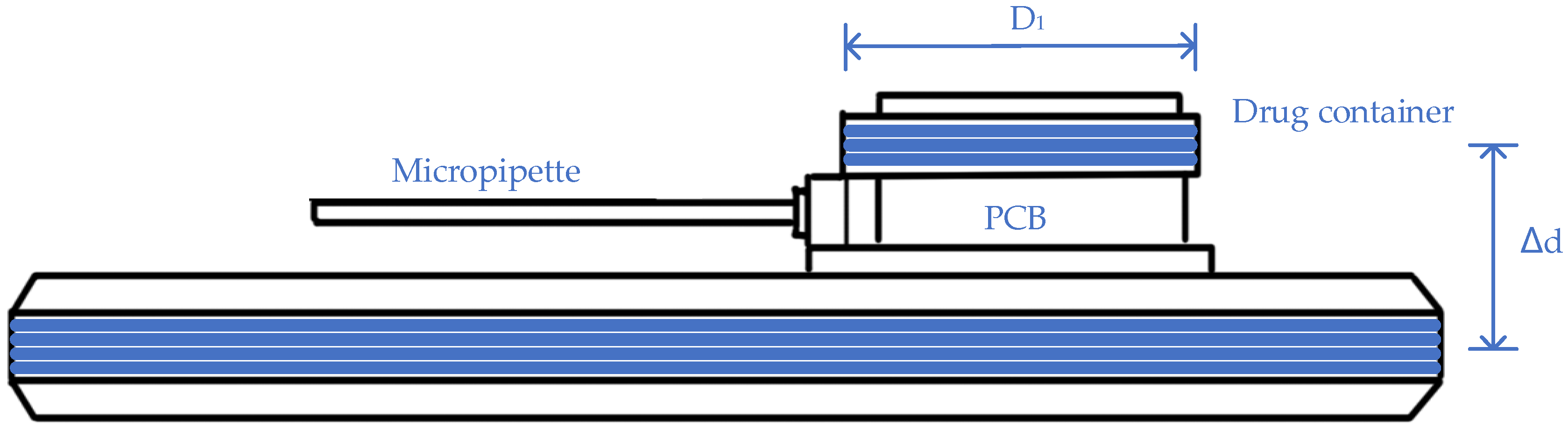
4.2.2. Passive Devices
- (1)
- Controlled timely administration: The WPT can precisely control the dissolution of gold sealing to release the drug in an optimal time range.
- (2)
- Efficient treatment: For central nervous system disorders, conventional treatments, such as oral ingestion and intravenous injection, are not efficient. This is due to a highly selective permeability of the blood–brain barrier, which complicates transporting processes. Implanted drug containers can release the drug directly to the lesion area without traditional penetration. This localized treatment could also minimize the side effects of drug with a low dosage and limited additional absorption [105].
- (3)
- Stable energy supply: For drug delivery systems with a relatively low power requested among implants, vertebrates’ daily activities could offer sufficient energy through body heating or movement [106,107]. Although the prospect of self-fulfillment is attractive, the power sources are less stable than that of WPT. The system would also require additional supporting devices.
- (1)
- Low power transfer efficiency: The non-planar structures of targeted organs indicate a possible bending of receiving antenna, which would lead to a relatively low power transfer efficiency.
- (2)
- Unnecessary operation duration: The function of WPT mainly focuses on the convenience and safety in the drug delivery system, while the duration is mainly controlled by the amount of implanted drug. Once the required dose is small enough that the administration could be activated by the power generated inside body [108], the necessity of WPT is doubted due to size concern.
- (3)
- Larger energy consumption than expected: The wireless actuator movement might be hindered by interstitial fluid. Therefore, a larger force than expected is required [96].
- (1)
- Adopting biocompatible materials to ensure the low hazardousness and high convenience;
- (2)
- Flexible implanted system to achieve the high accuracy and long duration;
- (3)
- In vivo/vitro tests to evaluate the result accuracy of numerical analysis and simulation;
- (4)
- Wearable transmitters rather than cages are vital for real human applications, which requires a high convenience standard.
5. Safety Standards and Regulations
5.1. Current Safety Guidelines
5.2. Special Requirements of Implantable Devices
- (1)
- Required specialized standards: Different from general exposure in the electromagnetic field, metallic implants could produce a potentially strong field. As the safety standards from IEEE and ICNIRP only include general exposure, the potential field generated by implants is currently defined as an untested condition [116]. To provide adequate protection for implant users, special standards are required with evaluations of currents, E-filed, or SAR in the human body [111]. Moreover, a combination of measurements with numerical simulations and experimental tests are encouraged to obtain a high level of detail and accuracy [117].
- (2)
- Difficulties of precise assessment: For medical implants, with frequencies from several hundred KHz to MHz, both electric and magnetic fields contribute to hazardous exposure. For near field applications, the electrical fields in tissue can be evaluated by SAR based on eddy current, which is the major contributor [118]. For the high frequency range, a significant enhancement of local absorption in the skin can be measured with standing wave effects, which is due to the reflections at the boundaries of tissues with strong dielectric contrast [119,120,121]. Furthermore, the drawbacks of inaccurate tissue modeling could exacerbate the difficulty of correct hazard assessment. The complexity of the human body indicates various in vitro model designs, in both structure and material aspects. For tissue, which is considered non-magnetic [122], the properties of conductivity and permittivity should be focused [123,124,125,126]. Different properties will affect tissue absorption and electric field distribution and further impact SAR [127,128].
- (3)
- Encapsulation: For implantable devices, the packaging material is a crucial topic to ensure biosafety. For WPT, the preferred metals could lead to hazardous impacts once they are implanted. In order to avoid these negative ramifications, encapsulating the whole system with biocompatible material is necessary [129,130]. Generally, the adopted encapsulation materials aligned with the original design of implanted biomedical devices, such as polydimethylsiloxane (PDMS), NuSil, etc. [8]. However, different encapsulations would also affect PTE. For the material concerns, metamaterials could intensify the electromagnetic field while ensuring that the mass augment is under control [131]. In contrast, encapsulation materials could also attenuate magnetic flux, which should be circumvented. Moreover, metallic shells would generate eddy currents, which would result in a temperature increase on the surfaces of the implants [70]. With these potential influences, the impact of encapsulation architecture should be taken into consideration.
- (4)
- Energy encryption: In addition to physical safety, information protection is crucial to avoid the privacy violations or data interface. Energy encryption [132], which is proposed in WPT for electric vehicles, aims to eliminate the possibility of receiving energy from unauthorized suppliers or transferring energy to unauthorized receivers. This cyber security is achieved by adopting chaotic encryption [133], which can avoid code-breaking, appropriate resonant converters, and control strategies to fulfill the power level and operational requirements. This system is designed for simultaneous multi-charging. For WPT in implantable devices, this process should be scaled down to meet the minimization requirement in order to guarantee charging safety.
6. Foresights and Development Trends
- (1)
- To develop control strategies or coils structures to enhance the tolerance of unanticipated misalignment and rotation;
- (2)
- To reduce the electromagnetic flux leakage to maintain a high transmission efficiency;
- (3)
- To apply metamaterials to wireless links while limiting a large mass increase to intensify electromagnetic field;
- (4)
- To integrate WPT and wireless information transmission into the same channel to form a hybrid system, hence manipulating power and control simultaneously;
- (5)
- To devise techniques for determining the transmission materials, hence maintaining an accurate simulation analysis;
- (6)
- To minimize the auxiliary circuits, compensation networks, and coils to ensure a minimal precarious influence;
- (7)
- To design the encryption methods for WPT to ensure no information leakage;
- (8)
- Other advanced design methodologies, control strategies, and new ideas to enhance the system performance of the implant devices.
7. Conclusions
- (1)
- For brain stimulations emphasizing the deciphering of brain functions, the current strategies all regard MHz operating frequency, which may affect the information transmission quality. As a result, the methods of combining wireless power transfer and wireless telecommunication are expected in the near future.
- (2)
- For peripheral stimulation focusing on long-term therapies, the current studies achieve a sufficient energy supply, but the safety issues are still waiting for exploration.
- (3)
- For the spinal stimulations with huge future potential, the wireless link designs are expected to have higher power levels and transfer efficiency.
- (4)
- For the pacemakers and cochlear implants, which are highly developed, their safety and reliability are highly required.
- (5)
- For the movable implants which are under developing, different coil combinations are proposed to enhance misalignment tolerance, while the overall power transfer efficiency is still quite low. Positioning strategy may be requested for further power transfer efficiency enhancement.
- (6)
- For endoscopy with short operating duration, the transfer of power to the receivers is feasible, while the potential of operating without a battery is expected.
- (7)
- For drug delivery systems with requested activation, wireless power transfer can be used for the temporary relocation of the whole device to enhance the preciseness of the system in the near future.
- (8)
- For safety standards currently focused on SAR, new regulations are expected to involve more details related to time, location, information linkage, and reliable simulation methods.
Author Contributions
Funding
Conflicts of Interest
References
- Mohseni, P.; Najafi, K. A 1.48-mw low-phase-noise analog frequency modulator for wireless biotelemetry. IEEE Trans. Biomed. Eng. 2005, 52, 938–943. [Google Scholar] [CrossRef]
- Yuce, M.R. Implementation of wireless body area networks for healthcare systems. Sens. Actuators A Phys. 2010, 162, 116–129. [Google Scholar] [CrossRef]
- Darwish, A.; Ismail Sayed, G.; Ella Hassanien, A. The Impact of Implantable Sensors in Biomedical Technology on the Future of Healthcare Systems. Intell. Pervasive Comput. Syst. Smarter Healthc. 2019, 67–89. [Google Scholar] [CrossRef]
- Schulman, J.H.; Dell, R.D.; Mann, A.E.; Faltys, M.A. Implantable Device with Improved Battery Recharging and Powering Configuration. U.S. Patent 6,067,474, 23 May 2000. [Google Scholar]
- Sun, T.; Xie, X.; Wang, Z. Wireless Power Transfer for Medical Microsystems; Springer: New York, NY, USA, 2013. [Google Scholar]
- Jawad, A.M.; Nordin, R.; Gharghan, S.K.; Jawad, H.M.; Ismail, M. Opportunities and Challenges for Near-Field Wireless Power Transfer: A Review. Energies 2017, 10, 1022. [Google Scholar] [CrossRef]
- Heo, M.S.; Moon, H.S.; Kim, H.C.; Park, H.W.; Lim, Y.H.; Paek, S.H. Fully Implantable Deep Brain Stimulation System with Wireless Power Transmission for Long-term Use in Rodent Models of Parkinson’s Disease. J. Korean Neurosurg. Soc. 2015, 57, 152–158. [Google Scholar] [CrossRef]
- Agarwal, K.; Jegadeesan, R.; Guo, Y.-X.; Thakor, N.V. Wireless power transfer strategies for implantable bioelectronics. IEEE Rev. Biomed. Eng. 2017, 10, 136–161. [Google Scholar] [CrossRef]
- Moore, J.; Castellanos, S.; Xu, S.; Wood, B.; Ren, H.; Tse, Z.T.H. Applications of Wireless Power Transfer in Medicine: State-of-the-Art Reviews. Ann. Biomed. Eng. 2019, 47, 22–38. [Google Scholar] [CrossRef]
- Rossini, P.M.; Barker, A.; Berardelli, A.; Caramia, M.; Caruso, G.; Cracco, R.; Dimitrijević, M.; Hallett, M.; Katayama, Y.; Lücking, C. Non-invasive electrical and magnetic stimulation of the brain, spinal cord and roots: Basic principles and procedures for routine clinical application. Report of an IFCN co mmittee. Electroencephalogr. Clin. Neurophysiol. 1994, 91, 79–92. [Google Scholar] [CrossRef]
- Balasubramaniam, S.; Wirdatmadja, S.A.; Barros, M.T.; Koucheryavy, Y.; Stachowiak, M.; Jornet, J.M. Wireless communications for optogenetics-based brain stimulation: Present technology and future challenges. IEEE Commun. Mag. 2018, 56, 218–224. [Google Scholar] [CrossRef]
- Nguyen, J.-P.; Nizard, J.; Keravel, Y.; Lefaucheur, J.-P. Invasive brain stimulation for the treatment of neuropathic pain. Nat. Rev. Neurol. 2011, 7, 699. [Google Scholar] [CrossRef]
- Ratnadurai-Giridharan, S.; Cheung, C.C.; Rubchinsky, L.L. Effects of electrical and optogenetic deep brain stimulation on synchronized oscillatory activity in parkinsonian basal ganglia. IEEE Trans. Neural Syst. Rehabil. Eng. 2017, 25, 2188–2195. [Google Scholar] [CrossRef] [PubMed]
- Manoufali, M.; Bialkowski, K.; Moha mmed, B.; Abbosh, A. Wireless power link based on inductive coupling for brain implantable medical devices. IEEE Antennas Wirel. Propag. Lett. 2017, 17, 160–163. [Google Scholar] [CrossRef]
- Monti, G.; De Paolis, M.V.; Tarricone, L. Wireless power transfer link for rechargeable deep brain stimulators. In Proceedings of the 2015 IEEE 15th Mediterranean Microwave Symposium (MMS), Lecce, Italy, 30 November–2 December 2015; pp. 1–4. [Google Scholar]
- Hashimoto, M.; Hata, A.; Miyata, T.; Hirase, H. Progra mmable wireless light-emitting diode stimulator for chronic stimulation of optogenetic molecules in freely moving mice. Neurophotonics 2014, 1, 011002. [Google Scholar] [CrossRef]
- Jeong, J.-W.; McCall, J.G.; Shin, G.; Zhang, Y.; Al-Hasani, R.; Kim, M.; Li, S.; Sim, J.Y.; Jang, K.-I.; Shi, Y. Wireless optofluidic systems for progra mmable in vivo pharmacology and optogenetics. Cell 2015, 162, 662–674. [Google Scholar] [CrossRef]
- Park, S.I.; Brenner, D.S.; Shin, G.; Morgan, C.D.; Copits, B.A.; Chung, H.U.; Pullen, M.Y.; Noh, K.N.; Davidson, S.; Oh, S.J. Soft, stretchable, fully implantable miniaturized optoelectronic systems for wireless optogenetics. Nat. Biotechnol. 2015, 33, 1280. [Google Scholar] [CrossRef] [PubMed]
- Baste, V.; Riise, T.; Moen, B.E. Radiofrequency electromagnetic fields; male infertility and sex ratio of offspring. Eur. J. Epidemiol. 2008, 23, 369–377. [Google Scholar] [CrossRef] [PubMed]
- Breckenkamp, J.; Berg-Beckhoff, G.; Münster, E.; Schüz, J.; Schlehofer, B.; Wahrendorf, J.; Blettner, M. Feasibility of a cohort study on health risks caused by occupational exposure to radiofrequency electromagnetic fields. Environ. Health 2009, 8, 23. [Google Scholar] [CrossRef]
- Habash, R.W.; Elwood, J.M.; Krewski, D.; Lotz, W.G.; McNamee, J.P.; Prato, F.S. Recent advances in research on radiofrequency fields and health: 2004–2007. J. Toxicol. Environ. Health Part. B 2009, 12, 250–288. [Google Scholar] [CrossRef] [PubMed]
- Valberg, P.A.; Van Deventer, T.E.; Repacholi, M.H. Workgroup report: Base stations and wireless networks—radiofrequency (RF) exposures and health consequences. Environ. Health Perspect. 2007, 115, 416–424. [Google Scholar] [CrossRef]
- Noh, K.N.; Park, S.I.; Qazi, R.; Zou, Z.; Mickle, A.D.; Grajales-Reyes, J.G.; Jang, K.I.; Gereau IV, R.W.; Xiao, J.; Rogers, J.A. Miniaturized, battery-free optofluidic systems with potential for wireless pharmacology and optogenetics. Small 2018, 14, 1702479. [Google Scholar] [CrossRef]
- Moradi, E.; Amendola, S.; Björninen, T.; Sydänheimo, L.; Carmena, J.M.; Rabaey, J.M.; Ukkonen, L. Backscattering neural tags for wireless brain-machine interface systems. IEEE Trans. Antennas Propag. 2014, 63, 719–726. [Google Scholar] [CrossRef]
- Nassirinia, F.; Straver, W.; Hoebeek, F.E.; Serdijn, W.A. Wireless power transfer and optogenetic stimulation of freely moving rodents. In Proceedings of the 2017 8th International IEEE/EMBS Conference on Neural Engineering (NER), Shanghai, China, 25–28 May 2017; pp. 456–460. [Google Scholar]
- Biswas, D.; Tasneem, N.; Hyde, J.; Sinclair, M.; Mahbub, I. Miniaturized wireless power transfer module design for brain optoelectronic implant. In Proceedings of the 2018 IEEE International Microwave Biomedical Conference (IMBioC), Philadelphia, PA, USA, 14–15 June 2018; pp. 163–165. [Google Scholar]
- Song, L.; Rahmat-Samii, Y. An end-to-end implanted brain–machine interface antenna system performance characterizations and development. IEEE Trans. Antennas Propag. 2017, 65, 3399–3408. [Google Scholar] [CrossRef]
- Mashhadi, I.A.; Pahlevani, M.; Hor, S.; Pahlevani, H.; Adib, E. A New Wireless Power-Transfer Circuit for Retinal Prosthesis. IEEE Trans. Power Electron. 2019, 34, 6425–6439. [Google Scholar] [CrossRef]
- Jegadeesan, R.; Guo, Y.-X. Modeling of wireless power transfer link for retinal implant. In Proceedings of the 2016 IEEE/ACES International Conference on Wireless Information Technology and Systems (ICWITS) and Applied Computational Electromagnetics (ACES), Honolulu, HI, USA, 13–18 March 2016; pp. 1–2. [Google Scholar]
- Shin, G.; Gomez, A.M.; Al-Hasani, R.; Jeong, Y.R.; Kim, J.; Xie, Z.; Banks, A.; Lee, S.M.; Han, S.Y.; Yoo, C.J. Flexible near-field wireless optoelectronics as subdermal implants for broad applications in optogenetics. Neuron 2017, 93, 509–521. [Google Scholar] [CrossRef]
- Wong, M.D.S.; Ng, K.A.; Nag, S.; Jegadeesan, R.; Leong, K.-W.; Ong, L.J.; Rusly, A.; Alam, M.; Ga mmad, G.G.L.; Tsai, C.W. A chronic implantable EMG recording system with wireless power and data transfer. In Proceedings of the 2017 IEEE Biomedical Circuits and Systems Conference (BioCAS), Turin, Italy, 19–21 October 2017; pp. 1–4. [Google Scholar]
- Lee, B.; Koripalli, M.K.; Jia, Y.; Acosta, J.; Sendi, M.S.E.; Choi, Y.; Ghovanloo, M. An Implantable Peripheral Nerve Recording and Stimulation System for Experiments on Freely Moving Animal Subjects. Sci. Rep. 2018, 8, 6115. [Google Scholar] [CrossRef] [PubMed]
- Mickle, A.D.; Won, S.M.; Noh, K.N.; Yoon, J.; Meacham, K.W.; Xue, Y.; McIlvried, L.A.; Copits, B.A.; Samineni, V.K.; Crawford, K.E.; et al. A wireless closed-loop system for optogenetic peripheral neuromodulation. Nature 2019, 565, 361–365. [Google Scholar] [CrossRef]
- Sivaji, V.; Grasse, D.W.; Hays, S.A.; Bucksot, J.E.; Saini, R.; Kilgard, M.P.; Rennaker, R.L., 2nd. ReStore: A wireless peripheral nerve stimulation system. J. Neurosci. Methods 2019, 320, 26–36. [Google Scholar] [CrossRef]
- Tomioka, K.; Miyake, K.; Misawa, K.; Toyoda, K.; Ishizaki, T.; Kimura, M. Photosensing circuit using thin-film transistors for retinal prosthesis. Jpn. J. Appl. Phys. 2018, 57, 1002B1. [Google Scholar] [CrossRef]
- Rizzo, J.F., 3rd. Update on retinal prosthetic research: The Boston Retinal Implant Project. J. Neuroophthalmol. 2011, 31, 160–168. [Google Scholar] [CrossRef]
- Kelly, S.K.; Shire, D.B.; Chen, J.; Doyle, P.; Gingerich, M.D.; Drohan, W.A.; Theogarajan, L.S.; Cogan, S.F.; Wyatt, J.L.; Rizzo, J.F. Realization of a 15-channel, hermetically-encased wireless subretinal prosthesis for the blind. In Proceedings of the 2009 Annual International Conference of the IEEE Engineering in Medicine and Biology Society, Minneapolis, MN, USA, 3–6 September 2009; pp. 200–203. [Google Scholar]
- Chen, K.; Yang, Z.; Hoang, L.; Weiland, J.; Humayun, M.; Liu, W. An Integrated 256-Channel Epiretinal Prosthesis. IEEE J. Solid-State Circuits 2010, 45, 1946–1956. [Google Scholar] [CrossRef]
- Kelly, S.K.; Shire, D.B.; Chen, J.; Doyle, P.; Gingerich, M.D.; Cogan, S.F.; Drohan, W.A.; Behan, S.; Theogarajan, L.; Wyatt, J.L.; et al. A hermetic wireless subretinal neurostimulator for vision prostheses. IEEE Trans. Biomed. Eng 2011, 58, 3197–3205. [Google Scholar] [CrossRef]
- Shire, D.B.; Kelly, S.K.; Chen, J.; Doyle, P.; Gingerich, M.D.; Cogan, S.F.; Drohan, W.A.; Mendoza, O.; Theogarajan, L.; Wyatt, J.L.; et al. Development and implantation of a minimally invasive wireless subretinal neurostimulator. IEEE Trans. Biomed. Eng 2009, 56, 2502–2511. [Google Scholar] [CrossRef]
- Theogarajan, L.S. A Low-Power Fully ImplanTable 15-Channel Retinal Stimulator Chip. IEEE J. Solid-State Circuits 2008, 43, 2322–2337. [Google Scholar] [CrossRef]
- Zhao, Y.; Nandra, M.; Yu, C.-C.; Tai, Y.-c. High performance 3-coil wireless power transfer system for the 512-electrode epiretinal prosthesis. In Proceedings of the 2012 Annual International Conference of the IEEE Engineering in Medicine and Biology Society, San Diego, CA, USA, 28 August–1 September 2012; pp. 6583–6586. [Google Scholar]
- Tomioka, K.; Miyake, K.; Misawa, K.; Kimura, M. Biological Stimulation Performance of LTPS-TFTs Artificial Retina by Wireless Power Drive. In Proceedings of the 2018 25th International Workshop on Active-Matrix Flatpanel Displays and Devices (AM-FPD), Kyoto, Japan, 3–6 July 2018; pp. 1–2. [Google Scholar]
- Chen, J.; Ozawa, R.; Aghassian, D. Inductive Charger with Magnetic Shielding. U.S. Patent 9,636,508, 2 May 2017. [Google Scholar]
- Janssen, J.R.; Van den Heuvel, K.; Murphy, R.B. Charging-Induced Implant Operation. U.S. Patent 10,525,271, 7 January 2020. [Google Scholar]
- Meskens, W.; Ridler, O. Multi-Loop Implant Charger. U.S. Patent 10,530,177, 7 January 2020. [Google Scholar]
- Olson, D.P.; Phillips, W.C.; Schmeling, A.L. Inductively Rechargeable External Energy Source, Charger, System and Method for a Transcutaneous Inductive Charger for an Implantable Medical Device. U.S. Patent Application 16/450,399, 28 November 2019. [Google Scholar]
- Ridler, O.J.; Forrester, K. Implantable Medical Device Charging. U.S. Patent 10,511,189, 17 December 2019. [Google Scholar]
- Zeng, F.G.; Rebscher, S.; Harrison, W.; Sun, X.; Feng, H. Cochlear implants: System design, integration, and evaluation. IEEE Rev. Biomed. Eng 2008, 1, 115–142. [Google Scholar] [CrossRef]
- Bocan, K.N.; Sejdić, E. Adaptive transcutaneous power transfer to implantable devices: A state of the art review. Sensors 2016, 16, 393. [Google Scholar] [CrossRef]
- Clark, G. Cochlear implants. In Speech Processing in the Auditory System; Springer: New York, NY, USA, 2004; pp. 422–462. [Google Scholar]
- Niparko, J.K. Cochlear Implants: Principles & Practices; Lippincott Williams & Wilkins: Philadelphia, PA, USA, 2009. [Google Scholar]
- Maltan, A.A.; Miller, D.; Harrison, W.V. Cochlear Implant Sound Processor with pErmanently Integrated Replenishable Power Source. U.S. Patent 7,349,741, 25 March 2008. [Google Scholar]
- Grover, P.; Sahai, A. Shannon meets Tesla: Wireless information and power transfer. In Proceedings of the 2010 IEEE International Symposium on Information Theory, Austin, TX, USA, 13–18 June 2010; pp. 2363–2367. [Google Scholar]
- Hochmair, I.; Nopp, P.; Jolly, C.; Schmidt, M.; Schößer, H.; Garnham, C.; Anderson, I. MED-EL cochlear implants: State of the art and a glimpse into the future. Trends Amplif. 2006, 10, 201–219. [Google Scholar] [CrossRef]
- Patrick, J.F.; Busby, P.A.; Gibson, P.J. The development of the Nucleus® Freedom™ cochlear implant system. Trends Amplif. 2006, 10, 175–200. [Google Scholar] [CrossRef] [PubMed]
- Giannantonio, S.; Di Nardo, W.; Schinaia, L.; Paludetti, G. Adaptation of cochlear implant fitting to various telecommunication systems: A proposal for a ‘telephone map’. Acta Oto-Laryngol. 2014, 134, 802–812. [Google Scholar] [CrossRef] [PubMed]
- Ivancsits, S.; Diem, E.; Pilger, A.; Rüdiger, H.W.; Jahn, O. Induction of DNA strand breaks by intermittent exposure to extremely-low-frequency electromagnetic fields in human diploid fibroblasts. Mutation Res./Genet. Toxicol. Environ. Mutagen. 2002, 519, 1–13. [Google Scholar] [CrossRef]
- Mann, K.; Wagner, P.; Brunn, G.; Hassan, F.; Hiemke, C.; Röschke, J. Effects of pulsed high-frequency electromagnetic fields on the neuroendocrine system. Neuroendocrinology 1998, 67, 139–144. [Google Scholar] [CrossRef] [PubMed]
- Zhou, H.; Xu, Q.; He, J.; Ren, H.; Zhou, H.; Zheng, K. A fully implanted progra mmable stimulator based on wireless communication for epidural spinal cord stimulation in rats. J. Neurosci. Methods 2012, 204, 341–348. [Google Scholar] [CrossRef] [PubMed]
- Liu, Z.; Zhong, Z.; Guo, Y.-X. In vivo high-efficiency wireless power transfer with multisine excitation. IEEE Trans. Microw. Theory Tech. 2017, 65, 3530–3540. [Google Scholar] [CrossRef]
- Hsu, C.-H.; Tseng, S.-B.; Hsieh, Y.-J.; Wang, C.-C. One-time-implantable spinal cord stimulation system prototype. IEEE Trans. Biomed. Circuits Syst. 2011, 5, 490–498. [Google Scholar] [CrossRef] [PubMed]
- Liang, C.K.; Young, G.S.; Chen, J.J.J.; Chen, C.K. A microcontroller-based implantable neuromuscular stimulation system with wireless power and data transmission for animal experiments. J. Chin. Inst. Eng. 2003, 26, 493–501. [Google Scholar] [CrossRef]
- Campi, T.; Cruciani, S.; De Santis, V.; Palandrani, F.; Maradei, F.; Feliziani, M. Induced Effects in a Pacemaker Equipped with a Wireless Power Transfer Charging System. IEEE Trans. Magn. 2017, 53, 1–4. [Google Scholar] [CrossRef]
- Mallela, V.S.; Ilankumaran, V.; Rao, N.S. Trends in cardiac pacemaker batteries. Indian Pacing Electrophysiol. J. 2004, 4, 201. [Google Scholar]
- Liu, C.; Jiang, C.; Song, J.; Chau, K.T. An Effective Sandwiched Wireless Power Transfer System for Charging Implantable Cardiac Pacemaker. IEEE Trans. Ind. Electron. 2019, 66, 4108–4117. [Google Scholar] [CrossRef]
- Wang, J.; Koyama, S.; Komatsubara, Y.; Suzuki, Y.; Taki, M.; Miyakoshi, J. Effects of a 2450 MHz high-frequency electromagnetic field with a wide range of SARs on the induction of heat-shock proteins in A172 cells. Bioelectromagn. J. Bioelectromagn. Soc. Soc. Phys. Regul. Biol. Med. Eur. Bioelectromagn. Assoc. 2006, 27, 479–486. [Google Scholar] [CrossRef]
- Xiao, C.; Cheng, D.; Wei, K. An LCC-C compensated wireless charging system for implantable cardiac pacemakers: Theory, experiment, and safety evaluation. IEEE Trans. Power Electron. 2017, 33, 4894–4905. [Google Scholar] [CrossRef]
- Campi, T.; Cruciani, S.; Palandrani, F.; De Santis, V.; Hirata, A.; Feliziani, M. Wireless Power Transfer Charging System for AIMDs and Pacemakers. IEEE Trans. Microw. Theory Tech. 2016, 64, 633–642. [Google Scholar] [CrossRef]
- Campi, T.; Cruciani, S.; De Santis, V.; Feliziani, M. EMF Safety and Thermal Aspects in a Pacemaker Equipped with a Wireless Power Transfer System Working at Low Frequency. IEEE Trans. Microw. Theory Tech. 2016, 64, 375–382. [Google Scholar] [CrossRef]
- Xiao, C.; Wei, K.; Cheng, D.; Liu, Y. Wireless charging system considering eddy current in cardiac pacemaker shell: Theoretical modeling, experiments, and safety simulations. IEEE Trans. Ind. Electron. 2016, 64, 3978–3988. [Google Scholar] [CrossRef]
- Abiri, P.; Abiri, A.; Packard, R.R.S.; Ding, Y.; Yousefi, A.; Ma, J.; Bersohn, M.; Nguyen, K.L.; Markovic, D.; Moloudi, S.; et al. Inductively powered wireless pacing via a miniature pacemaker and remote stimulation control system. Sci. Rep. 2017, 7, 6180. [Google Scholar] [CrossRef] [PubMed]
- Lyu, H.; John, M.; Burkland, D.; Greet, B.; Xi, Y.; Sampaio, L.C.; Taylor, D.A.; Babakhani, A.; Razavi, M. Leadless multisite pacing: A feasibility study using wireless power transfer based on Langendorff rodent heart models. J. Cardiovasc. Electrophysiol. 2018, 29, 1588–1593. [Google Scholar] [CrossRef]
- Frecker, M.I.; Haluck, R.S.; Dziedzic, R.P.; Schadler, J.R. Multifunctional Tool and Method for Minimally Invasive Surgery. U.S. Patent 7,208,005, 24 April 2007. [Google Scholar]
- Basar, M.R.; Ahmad, M.Y.; Cho, J.; Ibrahim, F. Application of wireless power transmission systems in wireless capsule endoscopy: An overview. Sensors 2014, 14, 10929–10951. [Google Scholar] [CrossRef]
- Abid, A.; O’Brien, J.M.; Bensel, T.; Cleveland, C.; Booth, L.; Smith, B.R.; Langer, R.; Traverso, G. Wireless power transfer to millimeter-sized gastrointestinal electronics validated in a swine model. Sci. Rep. 2017, 7, 46745. [Google Scholar] [CrossRef]
- Sun, T.; Xie, X.; Li, G.; Gu, Y.; Deng, Y.; Wang, Z. A two-hop wireless power transfer system with an efficiency-enhanced power receiver for motion-free capsule endoscopy inspection. IEEE Trans. Biomed. Eng. 2012, 59, 3247–3254. [Google Scholar]
- Basar, M.R.; Ahmad, M.Y.; Cho, J.; Ibrahim, F. An improved wearable resonant wireless power transfer system for biomedical capsule endoscope. IEEE Trans. Ind. Electron. 2018, 65, 7772–7781. [Google Scholar] [CrossRef]
- Luis, M.; Tavares, A.; Carvalho, L.S.; Lara-Santos, L.; Araújo, A.; de Mello, R.A. Personalizing therapies for gastric cancer: Molecular mechanisms and novel targeted therapies. World J. Gastroenterol. WJG 2013, 19, 6383. [Google Scholar] [CrossRef]
- Crew, K.D.; Neugut, A.I. Epidemiology of gastric cancer. World J. Gastroenterol. WJG 2006, 12, 354. [Google Scholar] [CrossRef]
- Van Cutsem, E.; Sagaert, X.; Topal, B.; Haustermans, K.; Prenen, H. Gastric cancer. Lancet 2016, 388, 2654–2664. [Google Scholar] [CrossRef]
- Søreide, K.; Sandvik, O.M.; Søreide, J.A.; Giljaca, V.; Jureckova, A.; Bulusu, V.R. Global epidemiology of gastrointestinal stromal tumours (GIST): A systematic review of population-based cohort studies. Cancer Epidemiol. 2016, 40, 39–46. [Google Scholar] [CrossRef] [PubMed]
- Nishida, T.; Blay, J.-Y.; Hirota, S.; Kitagawa, Y.; Kang, Y.-K. The standard diagnosis, treatment, and follow-up of gastrointestinal stromal tumors based on guidelines. Gastric Cancer 2016, 19, 3–14. [Google Scholar] [CrossRef] [PubMed]
- Cheung, K.-S.; Leung, W.K. Gastrointestinal bleeding in patients on novel oral anticoagulants: Risk, prevention and management. World J. Gastroenterol. 2017, 23, 1954. [Google Scholar] [CrossRef] [PubMed]
- Yu, S.; Guozheng, Y.; Zhiwei, J.; Bingquan, Z. The design and implementation of the wireless power transmission system of video capsule endoscopy. In Proceedings of the 2012 International Conference on Biomedical Engineering and Biotechnology, Macao, China, 28–30 May 2012; pp. 578–581. [Google Scholar]
- Wang, X.; Meng, M.Q. Application of a magnetic dipole modelling approach to the problem of tracking a capsule endoscope. Proc. Inst. Mech.Eng. Part H J. Eng. Med. 2011, 225, 377–387. [Google Scholar] [CrossRef]
- Pan, G.; Xin, W.; Yan, G.; Chen, J. A video wireless capsule endoscopy system powered wirelessly: Design, analysis and experiment. Meas. Sci. Technol. 2011, 22, 065802. [Google Scholar] [CrossRef]
- Xin, W.; Yan, G.; Wang, W. Study of a wireless power transmission system for an active capsule endoscope. Int. J. Med. Robot. Comput. Assist. Surg. 2010, 6, 113–122. [Google Scholar] [CrossRef]
- Na, K.; Jang, H.; Ma, H.; Bien, F. Tracking optimal efficiency of magnetic resonance wireless power transfer system for biomedical capsule endoscopy. IEEE Trans. Microw. Theory Tech. 2014, 63, 295–304. [Google Scholar] [CrossRef]
- He, S.; Yan, G.-Z.; Ke, Q.; Wang, Z.-W.; Chen, W.-W. A wirelessly powered expanding-extending robotic capsule endoscope for human intestine. Int. J. Precis. Eng. Manuf. 2015, 16, 1075–1084. [Google Scholar] [CrossRef]
- Ke, Q.; Luo, W.; Yan, G.; Yang, K. Analytical model and optimized design of power transmitting coil for inductively coupled endoscope robot. IEEE Trans. Biomed. Eng. 2015, 63, 694–706. [Google Scholar] [CrossRef]
- Basar, M.R.; Ahmad, M.Y.; Cho, J.; Ibrahim, F. Stable and high-efficiency wireless power transfer system for robotic capsule using a modified Helmholtz coil. IEEE Trans. Ind. Electron. 2016, 64, 1113–1122. [Google Scholar] [CrossRef]
- Jia, Z.; Yan, G.; Liu, H.; Wang, Z.; Jiang, P.; Shi, Y. The optimization of wireless power transmission: Design and realization. Int. J. Med. Robot. Comput. Assist. Surg. 2012, 8, 337–347. [Google Scholar] [CrossRef]
- Smith, S.; Tang, T.; Terry, J.; Stevenson, J.; Flynn, B.; Reekie, H.; Murray, A.; Gundlach, A.; Renshaw, D.; Dhillon, B. Development of a miniaturised drug delivery system with wireless power transfer and communication. IET Nanobiotechnol. 2007, 1, 80–86. [Google Scholar] [CrossRef] [PubMed]
- Tng, D.J.H.; Hu, R.; Song, P.; Roy, I.; Yong, K.-T. Approaches and challenges of engineering implantable microelectromechanical systems (MEMS) drug delivery systems for in vitro and in vivo applications. Micromachines 2012, 3, 615–631. [Google Scholar] [CrossRef]
- Cobo, A.; Sheybani, R.; Tu, H.; Meng, E. A Wireless Implantable Micropump for Chronic Drug Infusion Against Cancer. Sens. Actuators A Phys. 2016, 239, 18–25. [Google Scholar] [CrossRef] [PubMed]
- Cheong, H.R.; Nguyen, N.T.; Khaw, M.K.; Teoh, B.Y.; Chee, P.S. Wirelessly activated device with an integrated ionic polymer metal composite (IPMC) cantilever valve for targeted drug delivery. Lab. Chip 2018, 18, 3207–3215. [Google Scholar] [CrossRef] [PubMed]
- Brown, M.B.; Martin, G.P.; Jones, S.A.; Akomeah, F.K. Dermal and transdermal drug delivery systems: Current and future prospects. Drug Deliv. 2006, 13, 175–187. [Google Scholar] [CrossRef]
- Cobo, A.; Tu, H.; Sheybani, R.; Meng, E. Characterization of a wireless implantable infusion micropump for small animal research under simulated in vivo conditions. In Proceedings of the 2014 IEEE Biomedical Circuits and Systems Conference (BioCAS) Proceedings, Lausanne, Switzerland, 22–24 October 2014; pp. 348–351. [Google Scholar]
- Sung, S.H.; Kim, Y.S.; Joe, D.J.; Mun, B.H.; You, B.K.; Keum, D.H.; Hahn, S.K.; Berggren, M.; Kim, D.; Lee, K.J. Flexible wireless powered drug delivery system for targeted administration on cerebral cortex. Nano Energy 2018, 51, 102–112. [Google Scholar] [CrossRef]
- Yi, Y.; Kosel, J. A remotely operated drug delivery system with dose control. Sens. Actuators A Phys. 2017, 261, 177–183. [Google Scholar] [CrossRef]
- Chang, X.L.; Chee, P.S.; Lim, E.H. A Microreservior-based Drug Delivery Device Using Ionic Polymer Metal Composite (IPMC) Actuator. In Proceedings of the TENCON 2018–2018 IEEE Region 10 Conference, Jeju, Korea, 28–31 October 2018; pp. 0899–0902. [Google Scholar]
- Chang, X.L.; Chee, P.S.; Lim, E.H.; Chong, W.C. Radio-frequency enabled ionic polymer metal composite (IPMC) actuator for drug release application. Smart Mater. Struct. 2018, 28, 015024. [Google Scholar] [CrossRef]
- Fong, J.; Xiao, Z.; Takahata, K. Wireless implantable chip with integrated nitinol-based pump for radio-controlled local drug delivery. Lab. Chip 2015, 15, 1050–1058. [Google Scholar] [CrossRef] [PubMed]
- Lesniak, M.S.; Brem, H. Targeted therapy for brain tumours. Nat. Rev. Drug Discov. 2004, 3, 499–508. [Google Scholar] [CrossRef] [PubMed]
- Harb, A. Energy harvesting: State-of-the-art. Renew. Energy 2011, 36, 2641–2654. [Google Scholar] [CrossRef]
- Kim, H.S.; Kim, J.-H.; Kim, J. A review of piezoelectric energy harvesting based on vibration. Int. J. Precis. Eng. Manuf. 2011, 12, 1129–1141. [Google Scholar] [CrossRef]
- Wei, X.; Liu, J. Power sources and electrical recharging strategies for implantable medical devices. Front. Energy Power Eng. China 2008, 2, 1–13. [Google Scholar] [CrossRef]
- International Commission on Non-Ionizing Radiation Protection. ICNIRP statement on the “guidelines for limiting exposure to time-varying electric, magnetic, and electromagnetic fields (up to 300 ghz)”. Health Phys. 2009, 97, 257–258. [Google Scholar] [CrossRef]
- International Commission on Non-Ionizing Radiation Protection. Guidelines for limiting exposure to time-varying electric and magnetic fields (1 Hz to 100 kHz). Health Phys. 2010, 99, 818–836. [Google Scholar]
- Christ, A.; Douglas, M.; Nadakuduti, J.; Kuster, N. Assessing human exposure to electromagnetic fields from wireless power transmission systems. Proc. IEEE 2013, 101, 1482–1493. [Google Scholar] [CrossRef]
- Madjar, H.M. Human radio frequency exposure limits: An update of reference levels in Europe, USA, Canada, China, Japan and Korea. In Proceedings of the 2016 International Symposium on Electromagnetic Compatibility-EMC EUROPE, Wroclaw, Poland, 5–9 September 2016; pp. 467–473. [Google Scholar]
- International Commission on Non-Ionizing Radiation Protection (ICNIRP) Guideline: Guidelines for limiting exposure to time-varying electric, magnetic, and electromagnetic fields (up to 300 GHz). Health Phys. 1998, 74, 494–522.
- Awal, M.R.; Jusoh, M.; Beson, M.C.; Sabapathy, T.; Kamarudin, M.; Basar, M. Frequency restrictions for wireless power transfer of implantable medical devices. ARPN J. Eng. Appl. Sci. 2015, 10, 8707–8714. [Google Scholar]
- IEEE Standards Coordinating Committee. IEEE Standard for Safety Levels with Respect to Human Exposure to Radio Frequency Electromagnetic Fields, 3kHz to 300GHz; IEEE C95. 1-1991; IEEE: Piscataway, NJ, USA, 1992. [Google Scholar]
- Kyriakou, A.; Christ, A.; Neufeld, E.; Kuster, N. Local tissue temperature increase of a generic implant compared to the basic restrictions defined in safety guidelines. Bioelectromagnetics 2012, 33, 366–374. [Google Scholar] [CrossRef] [PubMed]
- Fields, R.E. Evaluating compliance with FCC guidelines for human exposure to radiofrequency electromagnetic fields. OET Bull. 1997, 65, 1–57. [Google Scholar]
- Kuster, N.; Balzano, Q. Energy absorption mechanism by biological bodies in the near field of dipole antennas above 300 MHz. IEEE Trans. Veh. Technol. 1992, 41, 17–23. [Google Scholar] [CrossRef]
- Barber, P.W.; Gandhi, O.P.; Hagmann, M.J.; Chatterjee, I. Electromagnetic absorption in a multilayered model of man. IEEE Trans. Biomed. Eng. 1979, 400–405. [Google Scholar] [CrossRef] [PubMed]
- Christ, A.; Klingenbock, A.; Samaras, T.; Goiceanu, C.; Kuster, N. The dependence of electromagnetic far-field absorption on body tissue composition in the frequency range from 300 MHz to 6 GHz. IEEE Trans. Microw. Theory Tech. 2006, 54, 2188–2195. [Google Scholar] [CrossRef]
- Schwan, H.; Li, K. Hazards due to total body irradiation by radar. Proc. IRE 1956, 44, 1572–1581. [Google Scholar] [CrossRef]
- Bocan, K.N.; Mickle, M.H.; Sejdić, E. Multi-disciplinary challenges in tissue modeling for wireless electromagnetic powering: A review. IEEE Sens. J. 2017, 17, 6498–6509. [Google Scholar] [CrossRef]
- Gabriel, C.; Gabriel, S.; Corthout, y.E. The dielectric properties of biological tissues: I. Literature survey. Phys. Med. Biol. 1996, 41, 2231. [Google Scholar] [CrossRef]
- Schwan, H.P.; PIERSOL, G.M. The absorption of electromagnetic energy in body tissues. A review and critical analysis. Am. J. Phys. Med. Rehabil. 1954, 33, 371–404. [Google Scholar]
- Gabriel, S.; Lau, R.; Gabriel, C. The dielectric properties of biological tissues: II. Measurements in the frequency range 10 Hz to 20 GHz. Phys. Med. Biol. 1996, 41, 2251. [Google Scholar] [CrossRef]
- Gabriel, S.; Lau, R.; Gabriel, C. The dielectric properties of biological tissues: III. Parametric models for the dielectric spectrum of tissues. Phys. Med. Biol. 1996, 41, 2271. [Google Scholar] [CrossRef] [PubMed]
- Paulides, M.M.; Verduijn, G.M.; Van Holthe, N. Status quo and directions in deep head and neck hyperthermia. Radiat. Oncol. 2016, 11, 21. [Google Scholar] [CrossRef] [PubMed]
- Wang, J.; Lim, E.; Leach, M.; Wang, Z.; Man, K. Review of SAR Measurement Methods in Relation to Wearable Devices. Eng. Lett. 2016, 24, 11–17. [Google Scholar]
- Byers, C.L.; Beazell, J.W.; Schulman, J.H.; Rostami, A. Hermetically Sealed Ceramic and Metal Package for Electronic Devices Implantable in Living Bodies. U.S. Patent 4,991,582, 12 February 1991. [Google Scholar]
- Kothari, M.; Chui, C. Hermetic Seal and Method to Create the Same. U.S. Patent 6,589,625, 8 July 2003. [Google Scholar]
- Sun, K.; Fan, R.; Zhang, X.; Zhang, Z.; Shi, Z.; Wang, N.; Xie, P.; Wang, Z.; Fan, G.; Liu, H. An overview of metamaterials and their achievements in wireless power transfer. J. Mater. Chem. C 2018, 6, 2925–2943. [Google Scholar] [CrossRef]
- Jiang, C.; Chau, K.; Liu, C.; Lee, C.H. An overview of resonant circuits for wireless power transfer. Energies 2017, 10, 894. [Google Scholar] [CrossRef]
- Wang, Z.; Chau, K.T.; Liu, C. Improvement of electromagnetic compatibility of motor drives using chaotic PWM. IEEE Trans. Magn. 2007, 43, 2612–2614. [Google Scholar] [CrossRef]


| Application | Category | Frequency | Input 1 | Output 2 | Efficiency 3 | Transmitting Distance | Transmitting Coil | Receiving Coil | Coating/Encapsulation 4 | Media |
|---|---|---|---|---|---|---|---|---|---|---|
| Cervical tumor cells [96] | Passive | 25 MHz | 0.6 W | 1 Vdc | N/A | 4.5 cm | N/A | ~ 10 × 10 mm2 | PDMS | 0.2% agarose gel & DI water |
| Cancer cells [99] | Active | 2 MHz | 9 V | 0.33 mA | N/A | 3 cm | Spiral 310 × 140 mm2 8 turns | Spiral D = 17 mm 6 turns | medical grade silicone & Parylene C | 1X PBS |
| Cancer cells [95] | Active | 2 MHz | 9 V/3 W | 0.33 mA | N/A | 3 cm | Spiral 310 × 140 mm2 8 turns | Spiral D = 17 mm 6 turns | medical grade silicone & Parylene C | 1X PBS & Mice |
| Cerebral cortex [100] | Passive | 13.56 MHz | 5 V/0.5 W | 1.34 µW | 1.22~0.06% | 0.5 cm | Annulus: Douter = 28 mm Dinner = 17 mm | Annulus: Douter = 24 mm Dinner = 14 mm | N/A | 1X PBS & Mice |
| General [101] | Passive | 6.7 MHz | 10 V | N/A | N/A | 0.15 cm | Annulus | Spiral D = 30 mm Thickness = 5 mm | Nafion & PDMS | Blue 38 & Air & DI water |
| General [102,103] | Passive | 13.64 MHz | N/A | 1.89 Vdc 0.65 W | N/A | 1~5 cm | N/A | ~ 10 × 10 mm2 | PDMS | Water |
| General [104] | Active | 185 MHz | 1.1 W | N/A | N/A | N/A | N/A | ~ 9.2 × 2.7 mm2 | Nitinol & Parylene C | Water |
| Guideline | Basic Restriction | Whole Body Avg. (W/kg) | Head/Trunk (W/kg) | Limbs (W/kg) |
|---|---|---|---|---|
| IEEE 2005 | Controllable | 0.4 | 10 | 20 |
| Uncontrollable | 0.08 | 1.6 (per 1 g) | 4 | |
| ICNIRP 2010 | Controllable | 0.4 | 10 | 20 |
| Uncontrollable | 0.08 | 2 | 4 | |
| ICNIRP 1998 | Controllable | 0.4 | 10 | 20 |
| Uncontrollable | 0.08 | 2 | 4 |
© 2020 by the authors. Licensee MDPI, Basel, Switzerland. This article is an open access article distributed under the terms and conditions of the Creative Commons Attribution (CC BY) license (http://creativecommons.org/licenses/by/4.0/).
Share and Cite
Zhou, Y.; Liu, C.; Huang, Y. Wireless Power Transfer for Implanted Medical Application: A Review. Energies 2020, 13, 2837. https://doi.org/10.3390/en13112837
Zhou Y, Liu C, Huang Y. Wireless Power Transfer for Implanted Medical Application: A Review. Energies. 2020; 13(11):2837. https://doi.org/10.3390/en13112837
Chicago/Turabian StyleZhou, Yujing, Chunhua Liu, and Yongcan Huang. 2020. "Wireless Power Transfer for Implanted Medical Application: A Review" Energies 13, no. 11: 2837. https://doi.org/10.3390/en13112837
APA StyleZhou, Y., Liu, C., & Huang, Y. (2020). Wireless Power Transfer for Implanted Medical Application: A Review. Energies, 13(11), 2837. https://doi.org/10.3390/en13112837