Non-Salient Brushless Synchronous Generator Main Exciter Design for More Electric Aircraft


Abstract
1. Introduction
2. Objectives and Scope
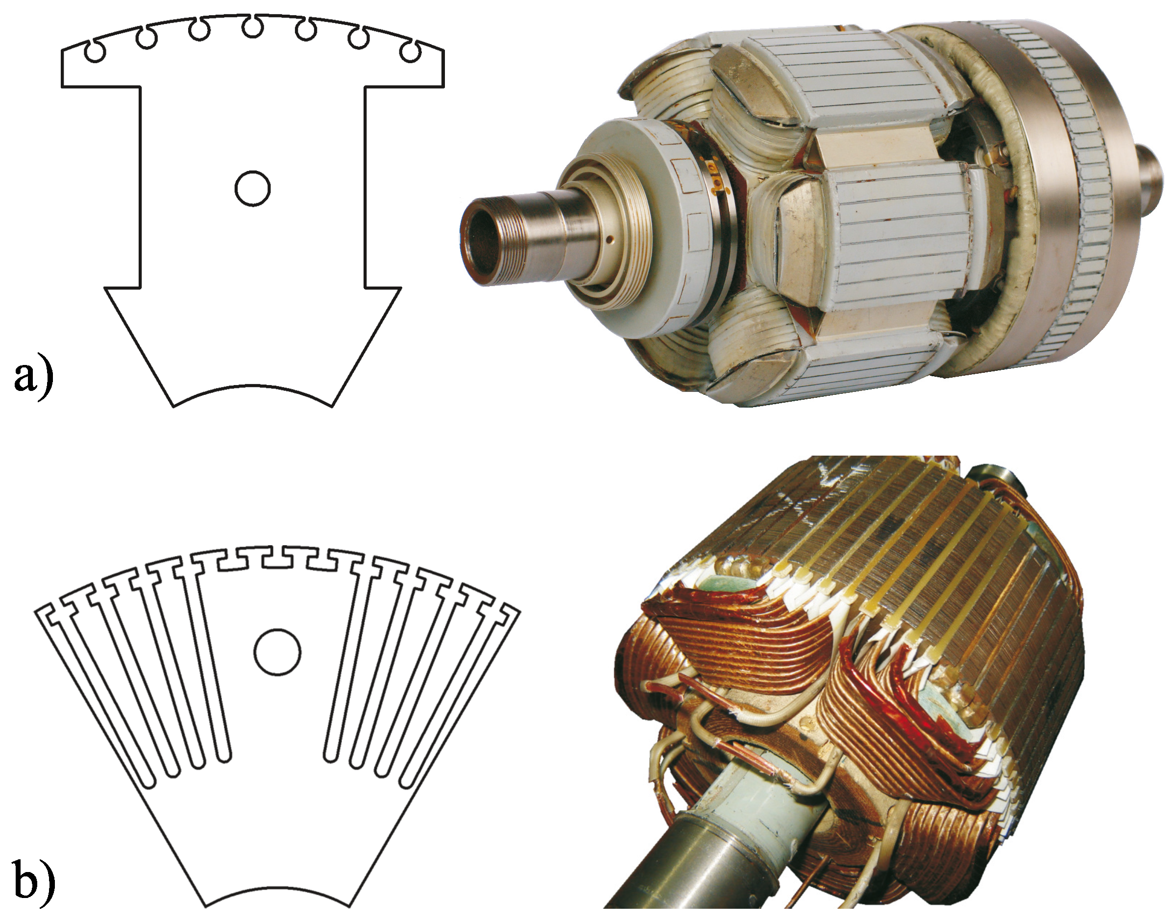
- more sinusoidal back EMF of the generated power due to more sinusoidal excitation winding magneto-motive force (MMF) spatial distribution,
- the possibility of reaching higher rotational velocities of modern MEA variable frequency power systems in future developments of BSG.
3. Solution
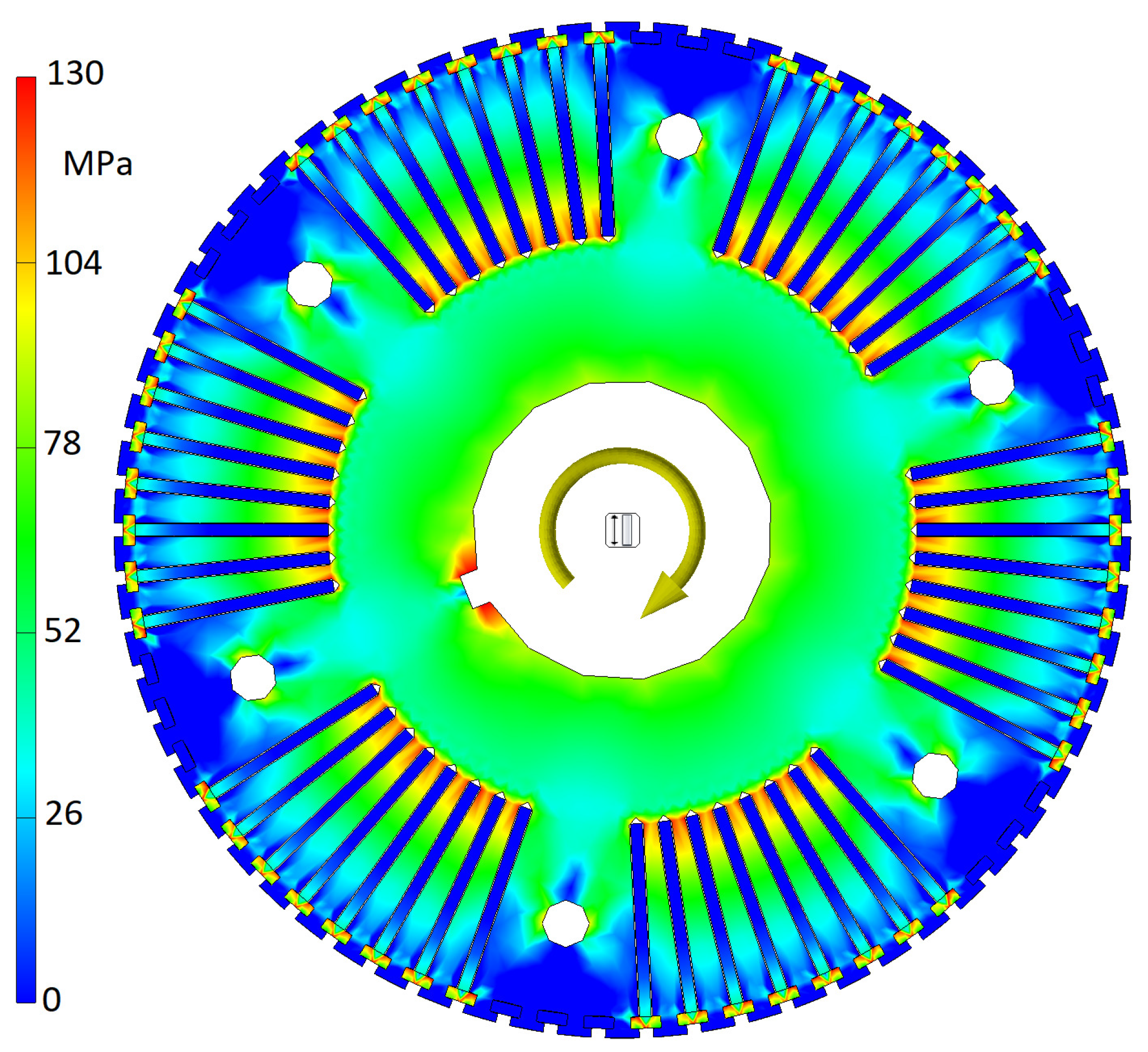
- The centrifugal force acting on rotor tooth—,
- The centrifugal force acting on the winding in the rotor slot .
4. Results
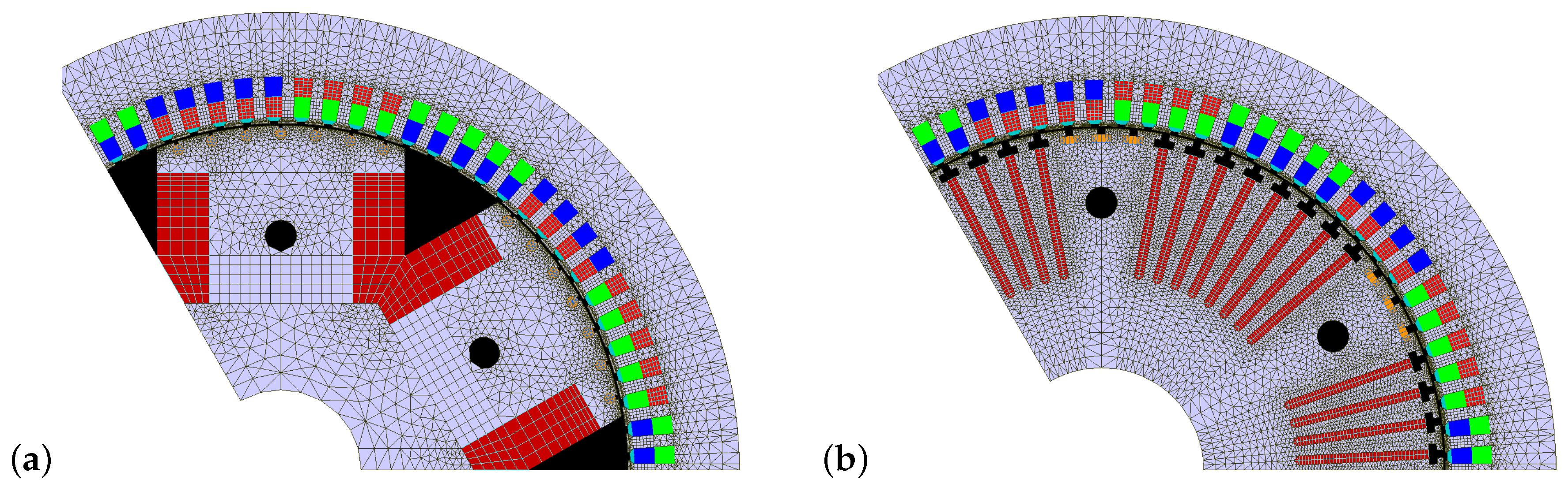
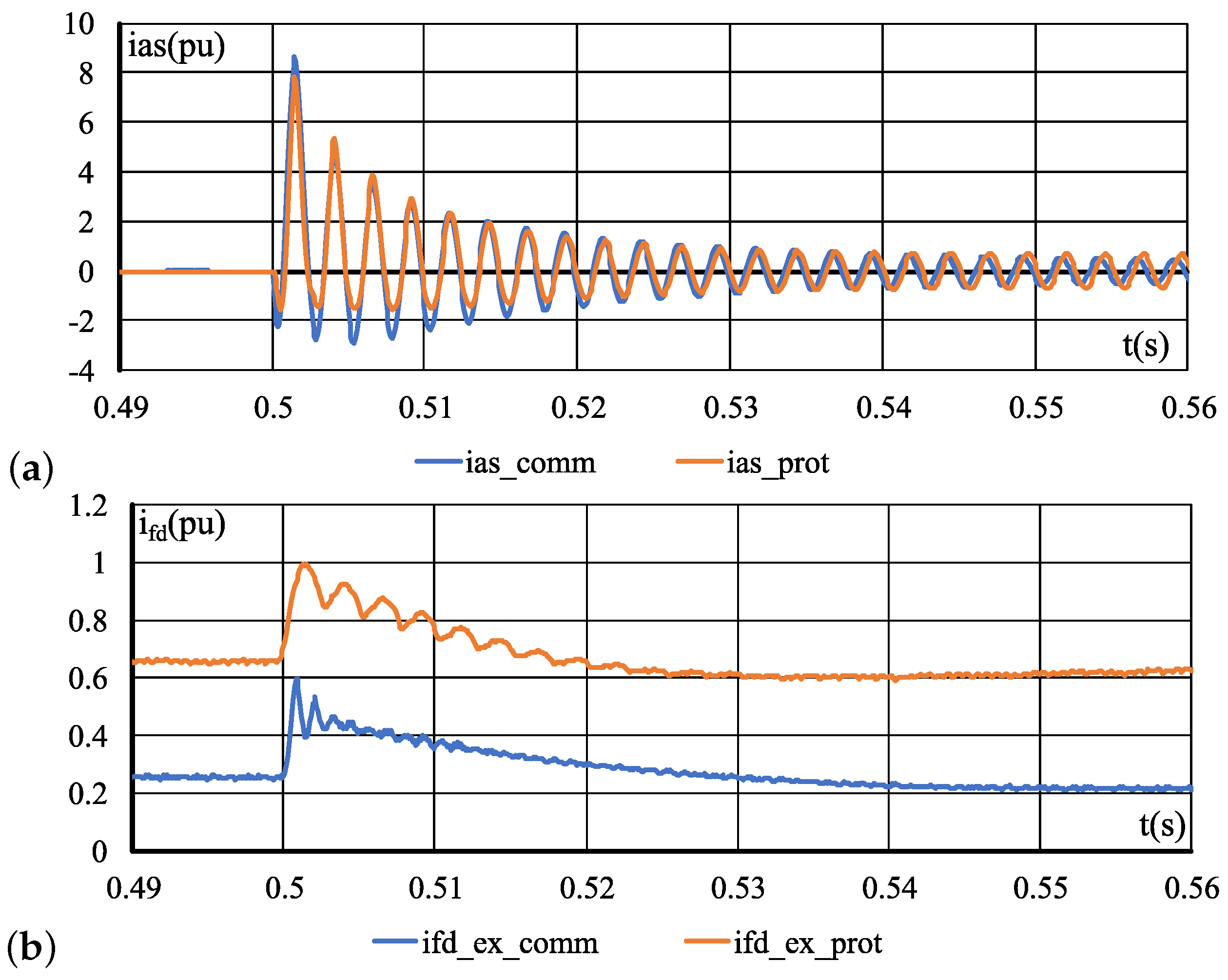
4.1. FEM Simulation
4.2. Measurements
5. Conclusions
Author Contributions
Funding
Conflicts of Interest
Abbreviations
| BSG | Brushless Synchronous Generator |
| EMF | Electromotive Force |
| FEM | Finite Element Method |
| GCU | Generator Control Unit |
| IM | Induction Machine |
| MEA | More Electric Aircraft |
| MMF | Magnetomotive Force |
| PM | Permanent Magnet |
| PMG | Permanent Magnet Generator |
| SR | Switched Reluctance |
References
- Ni, K.; Liu, Y.; Mei, Z.; Wu, T.; Hu, Y.; Wen, H.; Wang, Y. Electrical and Electronic Technologies in More-Electric Aircraft: A Review. IEEE Access 2019, 7, 76145–76166. [Google Scholar] [CrossRef]
- Emadi, K.; Ehsani, M. Aircraft power systems: Technology, state of the art, and future trends. IEEE Aerosp. Electron. Syst. Mag. 2000, 15, 28–32. [Google Scholar] [CrossRef]
- Barzegar, A.; Su, R.; Wen, C.; Rajabpour, L.; Zhang, Y.; Gupta, A.; Gajanayake, C.; Lee, M.Y. Intelligent power allocation and load management of more electric aircraft. In Proceedings of the 2015 IEEE 11th International Conference on Power Electronics and Drive Systems, Sydney, Australia, 9–12 June 2015; pp. 533–538. [Google Scholar] [CrossRef]
- Sarlioglu, B.; Morris, C.T. More Electric Aircraft: Review, Challenges, and Opportunities for Commercial Transport Aircraft. IEEE Trans. Transp. Electrif. 2015, 1, 54–64. [Google Scholar] [CrossRef]
- Kim, M.; Lee, S.; Bae, S. Decentralized Power Management for Electrical Power Systems in More Electric Aircrafts. Electronics 2018, 7, 187. [Google Scholar] [CrossRef]
- Chang, J.; Wang, A. New VF-power system architecture and evaluation for future aircraft. IEEE Trans. Aerosp. Electron. Syst. 2006, 42, 527–539. [Google Scholar] [CrossRef]
- Henke, M.; Narjes, G.; Hoffmann, J.; Wohlers, C.; Urbanek, S.; Heister, C.; Steinbrink, J.; Canders, W.R.; Ponick, B. Challenges and Opportunities of Very Light High-Performance Electric Drives for Aviation. Energies 2018, 11, 344. [Google Scholar] [CrossRef]
- Bu, F.; Liu, H.; Huang, W.; Hu, Y.; Degano, M.; Gerada, C.; Rajashekara, K. Induction-Machine-Based Starter/Generator Systems: Techniques, Developments, and Advances. IEEE Ind. Electron. Mag. 2020, 14, 4–19. [Google Scholar] [CrossRef]
- Nøland, J.K.; Leandro, M.; Suul, J.A.; Molinas, M.; Nilssen, R. Electrical Machines and Power Electronics For Starter-Generators in More Electric Aircrafts: A Technology Review. In Proceedings of the IECON 2019—45th Annual Conference of the IEEE Industrial Electronics Society, Lisbon, Portugal, 14–17 October 2019; Volume 1, pp. 6994–7001. [Google Scholar] [CrossRef]
- Zhang, Z.; Liu, Y.; Li, J. A HESM-Based Variable Frequency AC Starter-Generator System for Aircraft Applications. IEEE Trans. Energy Convers. 2018, 33, 1998–2006. [Google Scholar] [CrossRef]
- Wang, Y.; Nuzzo, S.; Zhang, H.; Zhao, W.; Gerada, C.; Galea, M. Challenges and Opportunities for Wound Field Synchronous Generators in Future More Electric Aircraft. IEEE Trans. Transp. Electrif. 2020. [Google Scholar] [CrossRef]
- Madonna, V.; Giangrande, P.; Galea, M. Electrical Power Generation in Aircraft: Review, Challenges, and Opportunities. IEEE Trans. Transp. Electrif. 2018, 4, 646–659. [Google Scholar] [CrossRef]
- Ganev, E. Selecting the Best Electric Machines for Electrical Power-Generation Systems: High-performance solutions for aerospace More electric architectures. IEEE Electrif. Mag. 2014, 2, 13–22. [Google Scholar] [CrossRef]
- Zhang, Z.; Li, J.; Liu, Y.; Xu, Y.; Yan, Y. Overview and development of variable frequency AC generators for more electric aircraft generation system. Chin. J. Electr. Eng. 2017, 3, 32–40. [Google Scholar] [CrossRef]
- Chen, Y.; Liu, B. Design and Analysis of a Five-Phase Fault-Tolerant Permanent Magnet Synchronous Motor for Aerospace Starter-Generator System. IEEE Access 2019, 7, 135040–135049. [Google Scholar] [CrossRef]
- Zhang, Z.; Huang, J.; Jiang, Y.; Geng, W.; Xu, Y. Overview and analysis of PM starter/generator for aircraft electrical power systems. CES Trans. Electr. Mach. Syst. 2017, 1, 117–131. [Google Scholar] [CrossRef]
- Borg Bartolo, J.; Gerada, C. Design and Modeling of a 45kW, Switched Reluctance Starter-Generator for a Regional Jet Application. In Proceedings of the SAE 2014 Aerospace Systems and Technology Conference, Cincinnati, UK, 23–25 September 2014. [Google Scholar] [CrossRef]
- Shoujun, S.; Weiguo, L.; Peitsch, D.; Schaefer, U. Detailed Design of a High Speed Switched Reluctance Starter/Generator for More/All Electric Aircraft. Chin. J. Aeronaut. 2010, 23, 216–226. [Google Scholar] [CrossRef]
- Ferreira, C.A.; Richter, E. Detailed Design of a 250-kW Switched Reluctance Starter/Generator for an Aircraft Engine. SAE Trans. 1993, 102, 289–300. [Google Scholar]
- Liu, H.; Bu, F.; Huang, W.; Liu, L.; Hu, Y.; Degano, M.; Gerada, C. Control Strategy for Five-Phase Dual-Stator Winding Induction Starter/Generator System. IEEE Trans. Ind. Electron. 2020, 67, 2607–2617. [Google Scholar] [CrossRef]
- Galea, M.; Giangrande, P.; Madonna, V.; Buticchi, G. Reliability-Oriented Design of Electrical Machines: The Design Process for Machines’ Insulation Systems MUST Evolve. IEEE Ind. Electron. Mag. 2020, 14, 20–28. [Google Scholar] [CrossRef]
- Pyrhonen, J.; Jokinen, T.; Hrabovcová, V. Design of Rotating Electrical Machines, 2nd ed.; Wiley: Chichester, UK, 2014. [Google Scholar]
- Asfirane, S.; Hlioui, S.; Amara, Y.; Gabsi, M. Study of a Hybrid Excitation Synchronous Machine: Modeling and Experimental Validation. Math. Comput. Appl. 2019, 24, 34. [Google Scholar] [CrossRef]
- Sun, L.; Zhang, Z.; Yu, L.; Gu, X. Development and Analysis of a New Hybrid Excitation Brushless DC Generator With Flux Modulation Effect. IEEE Trans. Ind. Electron. 2019, 66, 4189–4198. [Google Scholar] [CrossRef]
- Gieras, J.F. Advancements in Electric Machines; Power Systems; OCLC: 637451957; Springer: Dordrecht, The Netherlands, 2008. [Google Scholar]
- Lei, G.; Zhu, J.; Guo, Y. Multidisciplinary Design Optimization Methods for Electrical Machines and Drive Systems; Power Systems; Springer: Berlin/Heidelberg, Germany, 2016. [Google Scholar] [CrossRef]
- Ounis, H.; Sareni, B.; Roboam, X.; De Andrade, A. Multi-level integrated optimal design for power systems of more electric aircraft. Math. Comput. Simul. 2016, 130, 223–235. [Google Scholar] [CrossRef]
- Amrhein, M.; O’Connell, T.C.; Wells, J.R. An integrated design process for optimized high-performance electrical machines. In Proceedings of the 2013 International Electric Machines Drives Conference, Chicago, IL, USA, 12–15 May 2013; pp. 847–854. [Google Scholar]
- Buticchi, G.; Gerada, D.; Alberti, L.; Galea, M.; Wheeler, P.; Bozhko, S.; Peresada, S.; Zhang, H.; Zhang, C.; Gerada, C. Challenges of the Optimization of a High-Speed Induction Machine for Naval Applications. Energies 2019, 12, 2431. [Google Scholar] [CrossRef]
- Shin, K.H.; Bang, T.K.; Cho, H.W.; Choi, J.Y. Design and Analysis of High-Speed Permanent Magnet Synchronous Generator With Rotor Structure Considering Electromechanical Characteristics. IEEE Trans. Appl. Supercond. 2020, 30, 1–5. [Google Scholar] [CrossRef]
- Tosetti, M.; Maggiore, P.; Cavagnino, A.; Vaschetto, S. Conjugate Heat Transfer Analysis of Integrated Brushless Generators for More Electric Engines. IEEE Trans. Ind. Appl. 2014, 50, 2467–2475. [Google Scholar] [CrossRef]
- Huang, S.; Luo, J.; Leonardi, F.; Lipo, T. A general approach to sizing and power density equations for comparison of electrical machines. IEEE Trans. Ind. Appl. 1998, 34, 92–97. [Google Scholar] [CrossRef]
- Moreno, Y.; Almandoz, G.; Egea, A.; Madina, P.; Escalada, A.J. Multi-Physics Tool for Electrical Machine Sizing. Energies 2020, 13, 1651. [Google Scholar] [CrossRef]
- Honsinger, V. Sizing Equations for Electrical Machinery. IEEE Trans. Energy Convers. 1987, EC-2, 116–121. [Google Scholar] [CrossRef]
- Kutt, F.; Michna, M.; Kostro, G.; Ronkowski, M. Modelling of steady state and transient performance of the synchronous generator considering harmonic distortions caused by non-uniform saturation of the pole shoe. Electr. Power Syst. Res. 2017, 143, 409–414. [Google Scholar] [CrossRef]
- Kutt, F.; Michna, M.; Kostro, G. Multiple Reference Frame Theory in the Synchronous Generator Model Considering Harmonic Distortions Caused by Nonuniform Pole Shoe Saturation. IEEE Trans. Energy Convers. 2020, 35, 166–173. [Google Scholar] [CrossRef]
- More Open Electrical Technologies—TRIMIS—European Commission. 2013. Library Catalog: Trimis.ec.europa.eu. Available online: https://trimis.ec.europa.eu/sites/default/files/project/documents/20121218_094726_85827_MOET_Public_Technical_report.pdf (accessed on 10 May 2020).
- Arumugam, D.; Logamani, P.; Karuppiah, S. Electromagnetic & thermal analysis of synchronous generator with different rotor structures for aircraft application. Alex. Eng. J. 2018, 57, 1447–1457. [Google Scholar] [CrossRef]
- Biais, F.; Delhasse, F.; Thalin, P. Electrical Power Generation & Start Solutions for the Falcon 5X Program. In Proceedings of the 2015 More Electric Aircraft Conference, Toulouse, France, 3–5 February 2015; Available online: https://www.see.asso.fr/bitcache/91abc2ab86a3f5a69f5b8207260be67011b46135?vid=32132 (accessed on 26 May 2020).


| Parameter | Value | Description |
|---|---|---|
| 40 kVA | nominal power | |
| 208 V | nominal voltage | |
| 111 A | nominal current | |
| 400 Hz | nominal frequency | |
| nominal load power factor | ||
| 45 A | nominal field winding current | |
| p | 3 | number of pole pairs |
| m | 3 | number of phases |
| 81 | number of stator slots | |
| 66 | number of rotor slots | |
| 27 | number of armature winding turns | |
| mm | air gap length | |
| 175 mm | inner diameter of the stator | |
| l | 73 mm | machine length |
| 2 mm | stator and rotor slot opening |
| Part of the Magnetic Circuit | Flux Density (T) in Commercial BSG | Flux Density (T) in Prototype BSG |
|---|---|---|
| Airgap flux density | 0.8 | 0.8 |
| Stator yoke flux density | 1.45 | 1.46 |
| Stator tooth flux density | 1.58 | 1.6 |
| Rotor yoke flux density | 1.05 | 1.22 |
| Rotor slot/pole flux density | 1.66 | 1.66 |
© 2020 by the authors. Licensee MDPI, Basel, Switzerland. This article is an open access article distributed under the terms and conditions of the Creative Commons Attribution (CC BY) license (http://creativecommons.org/licenses/by/4.0/).
Share and Cite
Kutt, F.; Michna, M.; Kostro, G. Non-Salient Brushless Synchronous Generator Main Exciter Design for More Electric Aircraft. Energies 2020, 13, 2696. https://doi.org/10.3390/en13112696
Kutt F, Michna M, Kostro G. Non-Salient Brushless Synchronous Generator Main Exciter Design for More Electric Aircraft. Energies. 2020; 13(11):2696. https://doi.org/10.3390/en13112696
Chicago/Turabian StyleKutt, Filip, Michał Michna, and Grzegorz Kostro. 2020. "Non-Salient Brushless Synchronous Generator Main Exciter Design for More Electric Aircraft" Energies 13, no. 11: 2696. https://doi.org/10.3390/en13112696
APA StyleKutt, F., Michna, M., & Kostro, G. (2020). Non-Salient Brushless Synchronous Generator Main Exciter Design for More Electric Aircraft. Energies, 13(11), 2696. https://doi.org/10.3390/en13112696