Article

ANFTS Mode Control for an Electronically Controlled Hydraulic Power Steering System on a Permanent Magnet Slip Clutch

Department of Vehicle Engineering, Jiangsu University, Zhenjiang 212013, China
*
Author to whom correspondence should be addressed.
Energies 2019, 12(9), 1739; https://doi.org/10.3390/en12091739
Submission received: 14 April 2019 / Revised: 29 April 2019 / Accepted: 2 May 2019 / Published: 8 May 2019
(This article belongs to the Special Issue Adaptive Fuzzy Control)

Abstract

:
There are various uncertain factors such as parameter perturbation and external disturbance during the steering process of a permanent magnet slip clutch electronically controlled hydraulic power steering system (P-ECHPS) of medium and heavy duty vehicles, which is an electronically controlled hydraulic power steering system based on a permanent magnetic slip clutch (PMSC). In order to avoid the immutable single assistance characteristic of a hydraulic power steering system, a PMSC speed-controlled model and P-ECHPS of each subsystem model were studied. Combined with non-singular terminal sliding mode and fast terminal sliding mode, an Adaptive Non-singular Fast Terminal Sliding (ANFTS) mode control strategy was proposed to control precisely the rotor speed of the PMSC in P-ECHPS, thus achieving better power control for the entire P-ECHPS system. The simulation results show that adaptive nonsingular fast terminal sliding mode control enables PMSC output speed to track the target speed. Compared with the non-singular terminal sliding mode control and the ordinary sliding mode control, the convergence speed has been improved by 66.7% and 84.2%, respectively. The rapid control prototype test of PMSC based on dSPACE (dSPACE is a development and verification platform based on MATLAB/Simulink software.) was carried out. The validity of the adaptive NFTSM algorithm and the correctness of the offline simulation results are validated. The adaptive NFTSM algorithm have better robustness and can realize variable assist characteristics and save energy.

1. Introduction

The widespread traditional hydraulic power steering system (HPS) in heavy duty vehicles has some disadvantages. For example, HPS has a single assist characteristic and it wastes energy because the steering pump keeps running in a high speed regardless of its steering [1]. To solve this problem, an electronically controlled hydraulic power steering based on a permanent magnetic slip clutch was proposed, which is referred to as P-ECHPS. The Electronically Controlled Hydraulic Power Steering (ECHPS) system is mainly divided into flow control type [2,3,4], reaction type [5,6] and valve sensitive type [7]. The design scheme of the flow control type of the ECHPS system is adopted in this paper. During the steering process, P-ECHPS reveals various uncertain factors such as parameter perturbation and external disturbance and it requires a swift response for PMSC output speed. From the later experiment of this paper, we can see that the conventional PID (Proportion Integration Differentiation) control was difficult to obtain satisfactory control. PMSC is the critical component of P-ECHPS and how to control precisely the rotor speed of the PMSC is the key to achieve better power control, so it was necessary to combine the PMSC speed control problem with the actual requirements of P-ECHPS.
Sliding Mode Control (SMC) is a kind of nonlinear control, which has the advantages of insensitivity to the parameter changes and disturbances, strong robustness and simple physical implementation, etc. It is widely used in motor control [8]; However, the tracking error convergence to the zero point centre in a limited time is impossible, due to the sliding surface of traditional SMC is linear. The linear sliding surface’s weaknesses are obvious in the control of some complex and difficult nonlinear systems. With the purpose of improving the defects of the linear sliding surface, Zak [9] proposed to use the concept of a terminal attractor to create the Terminal Sliding Mode (TSM) in 1988. However, TSM also has singularities in practical applications. To tackle this problem, Feng [10] proposed an improved Non-singular Terminal Sliding Mode (NTSM) for TSM. Although the NTSM algorithm can guarantee convergence in a finite time and avoid singularity, its convergence speed will be slower when it is far away from zero. Therefore, the Non-singular Fast Terminal Sliding Mode (NFTSM) emerged, which ensures that the system state has fast convergence characteristics whether it is away from zero point centre or near zero [11].
In recent years, the NFTSM algorithm with many advantages has received special attention from research control algorithm scholars. Li et. al. [12] proposed an adaptive NFTSM control method including an adaptive control term and a robust control term for the electromechanical actuator control system. The adaptive control term uses the improved composite adaptive strategy to estimate the uncertainty of the parameters and compensate for the uncertainty of dynamic modeling. The robust control term guarantees the fast convergence of the error; Zhao et. al. [13] developed a decentralized adaptive control method based on the NFTSM algorithm which is applied in the field of position synchronization control of spacecraft to eliminate chattering and ensure fast convergence; Cheng et. al. [14] proposed the NFTSM algorithm based on state variables comprising the advantages of SMC and NTSM, using this algorithm to solve the problem that the position of a switched reluctance motor is difficult to control accurately, and achieving fast convergence.
The contributions of this paper are described as follows:
1. The composition and principle of the P-ECHPS are introduced. PMSC, the core component, of the P-ECHPS is studied. The PMSC speed regulation scheme and the mathematical model of PMSC speed regulation are established. Through the bench test, the value of the induction potential coefficient and the key characteristic parameter in the mathematical model of speed regulation are obtained. The hydraulic system group of the P-ECHPS is analyzed. Mathematical models of each part of the hydraulic system are established. According to the requirement of the P-ECHPS ideal boost characteristic, the simulation is carried out. According to the requirement of the P-ECHPS’s ideal assistant characteristic, the curve of the P-ECHPS’s assistant characteristic is obtained by simulation. Combined with the established hydraulic system model, the target rotation speed of PMSC’s inner rotor under different working conditions is obtained.
2. Considering the working characteristics of the P-ECHPS, a new control law of the adaptive NFTSM algorithm applied to the PMSC is proposed to precisely control the rotor speed of the PMSC, so as to achieve better control for the P-ECHPS. Through simulation analysis, the control effects of adaptive NFTSM are compared with PID, SMC and NTSM. The results show that the adaptive NFTSM algorithm has relatively fast convergence speed, strong robustness and good control performance. The simulation of P-ECHPS boost characteristics shows that the adaptive NFTSM algorithm achieves the variable boost characteristics of P-ECHPS.
3. A prototype test-bed for rapid control for PMSC based on dSPACE is constructed. Contrast experiments of PID and adaptive NFTSM control effect under interference and non-interference conditions are carried out. The results show that adaptive NFTSM can make PMSC track the target speed quickly and has strong robustness. The validity of the adaptive NFTSM algorithm and the correctness of off-line simulation results are verified.

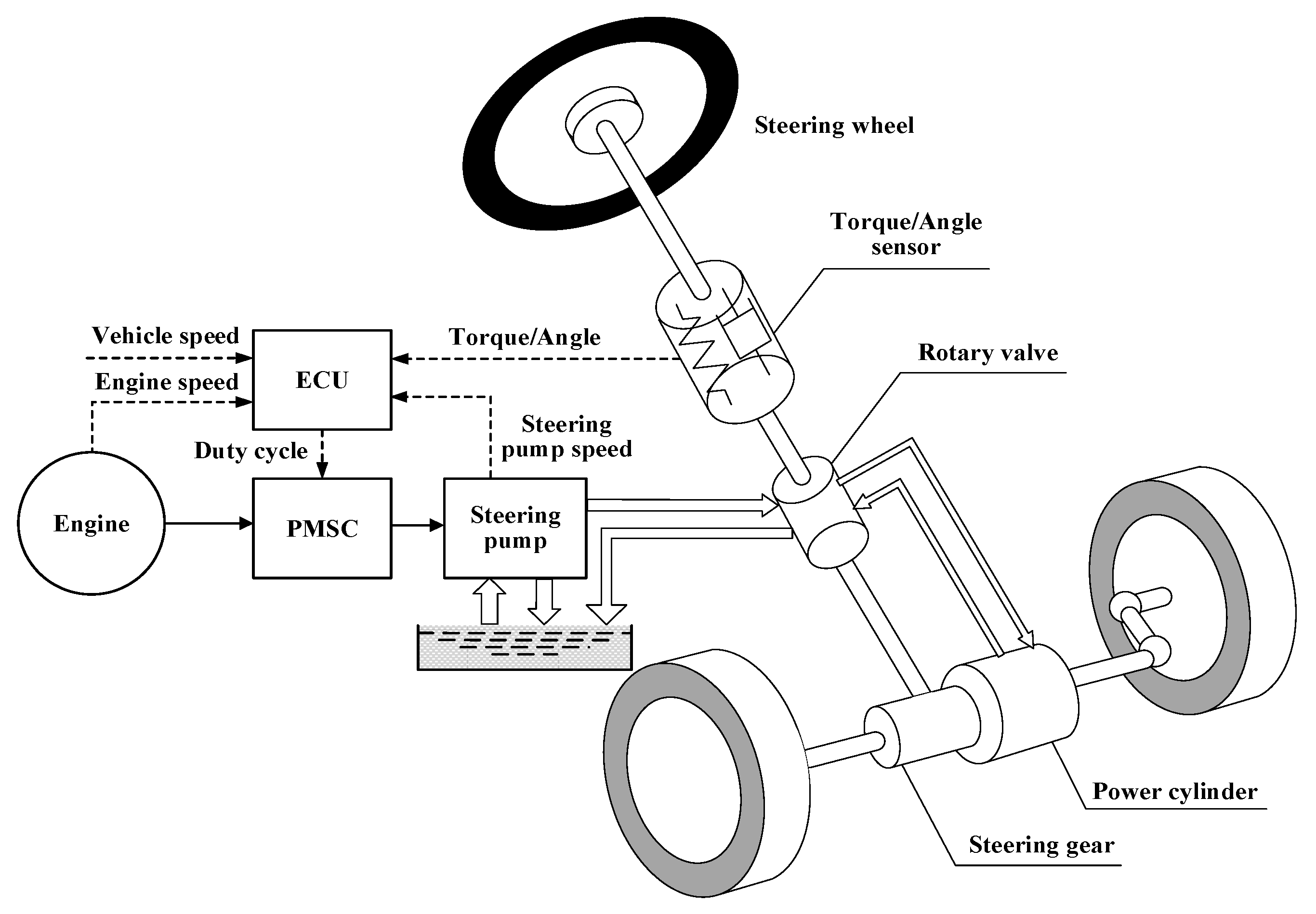
2. The Composition Principle of P-ECHPS

P-ECHPS, as shown in Figure 1, is the structure of HPS on the basic of PMSC building bridge between the engine and the steering. The principle of P-ECHPS is that an Electronically Controlled Unit (ECU) receives multiple sensor signals, including vehicle speed, engine speed, steering pump speed, torque/rotation angle, and the IGBT duty cycle externally connected to the PMSC outer rotor speed control circuit was calculated and outputted, and the rotor speed of the PMSC inner rotor can be adjusted. This changed the speed of the innner rotor are equivalent to altering the steering pump speed, changing the steering pump output flow, thereby determining the variable power and avoiding the flood waste of the steering pump, which reduces the energy consumption relative to the HPS.

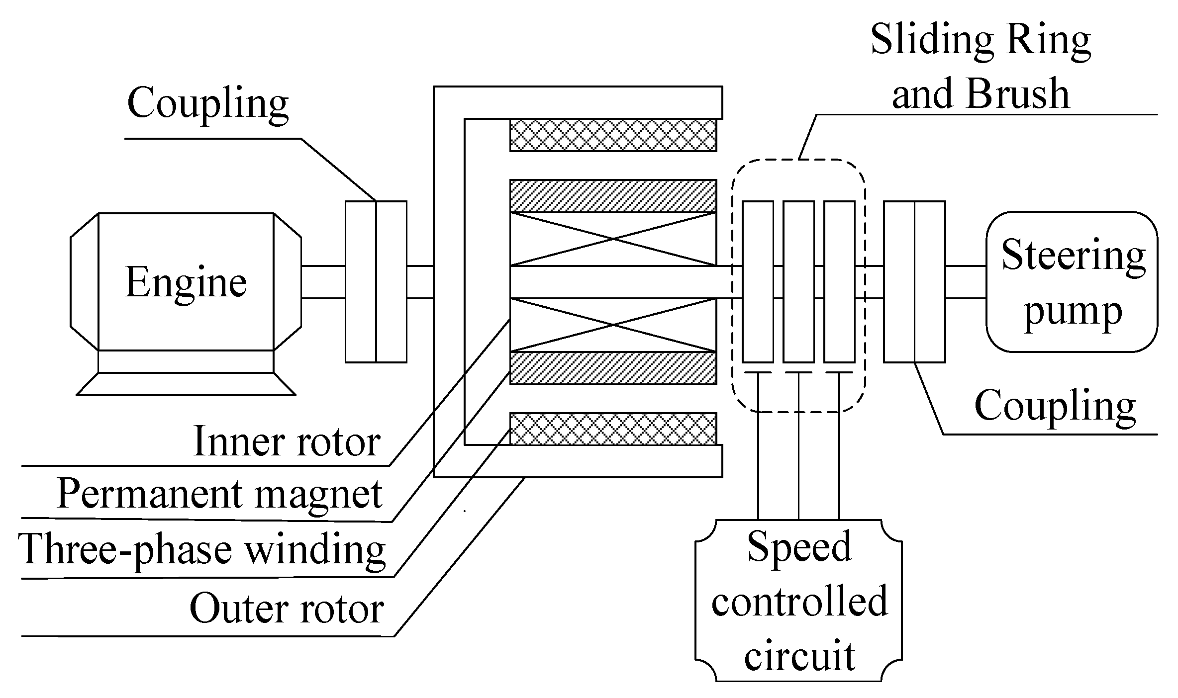
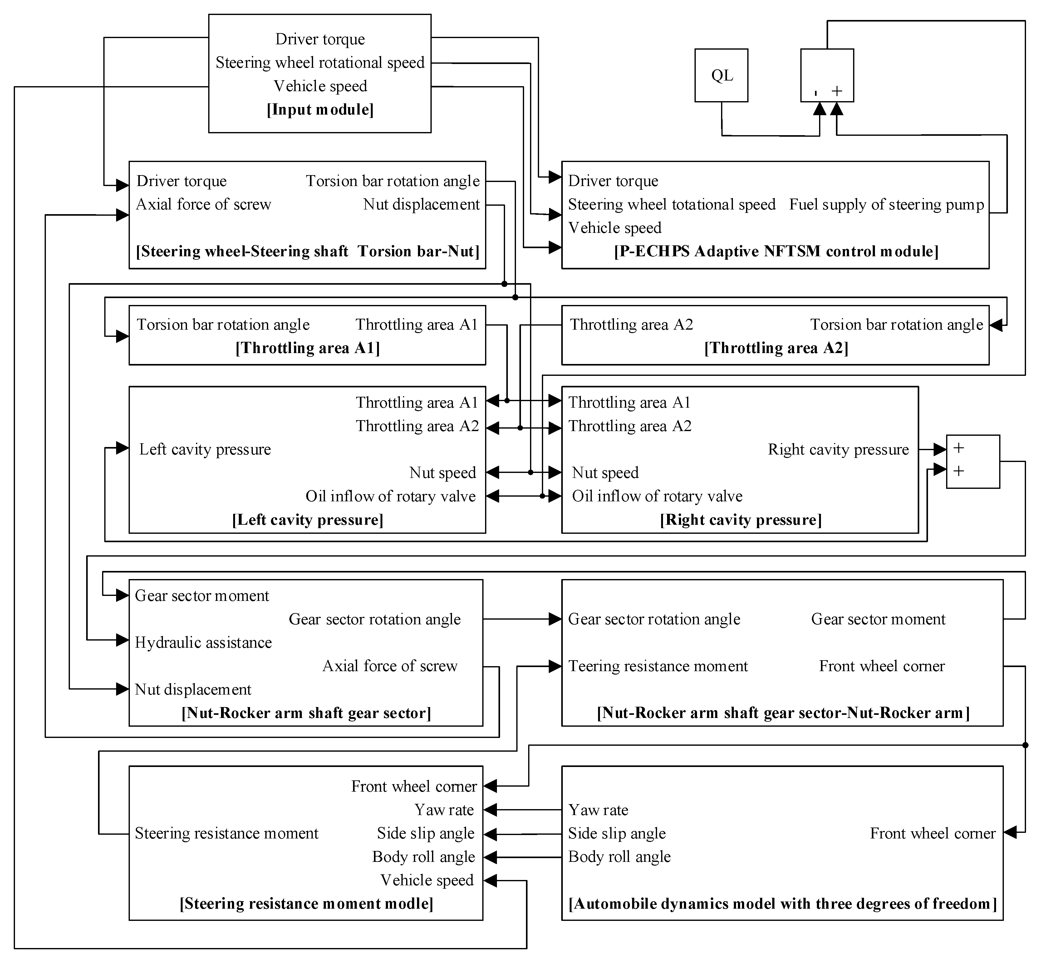
3. Structure and System Modeling of P-ECHPS

3.1. Speed Control Model of PMSC

The core of P-ECHPS is thought to have the ability of transmitting enough torque to drive the steering pump to achieve on-demand rotation and its basic structure including the speed of the outer rotor and inner rotor and external speed control circuit, as Figure 2 shows. The principle of PMSC is as follows: The PMSC is installed between the drive shaft and the load shaft. The permanent magnet establishes a constant main magnetic field in the pole of the inner rotor. When the outer rotor is driven by the driving shaft, the armature part cuts the main magnetic field and causes the induced current in the three-phase winding. The armature magnetic field and the main magnetic field are interlinked, establishing an electromagnetic torque between the inner and outer rotor. This torque drives the inner rotor and the load shaft to rotate at a certain speed. The magnitude of the torque depends on the strength of the main magnetic field and the slip between the inner and outer rotors.
Owing to the mechanical characteristics of the PMSC itself, the output speed of the inner rotor is far from the target speed required by the P-ECHPS under various working conditions in the real world. Therefore, the speed of the PMSC must be adjusted to make the inner rotor speed of the PMSC reach the target speed, ensuring that the P-ECHPS provides adjustable power by the on-demand output flow of the steering pump.
Consequently, the Boost chopper circuit of the external switching device IGBT on the outer rotor winding of the PMSC is used for speed regulation. Figure 3 is a speed control circuit diagram. By adjusting the IGBT duty cycle, the outer rotor winding loop potential and winding current Id can be altered, thereby changing the output torque of the PMSC inner rotor, and then turning the steering pump speed to achieve variable speed assist characteristics.
The dynamic mathematical model of Boost circuit applied in PMSC speed regulation is established by using the state space averaging method [15], and the average equivalent circuit voltage equation of the model is derived.
U d ( 1 D ) U c = L d I ˙ d + R I d
where Ud is induction electromotive force, UC is terminal voltage of capacitor, D is duty cycle, Ld is inductance, R is three-phase winding resistance of outer rotor.
The relationship between the induction potential Ud and the speed difference of the internal and external rotors in PMSC is as follows:
U d = k ( ω 1 ω 2 )
where k is induced electromotive force factor, ω1 is mechanical angular velocity of outer rotor, ω2 is mechanical angular velocity of inner rotor.
The knowledge of capacitance and inductance charging and discharging can be obtained as follows:
1 2 C U c 2 = 1 2 L d I d 2
where C is capacitance.
Referring to the chopper cascade speed regulation [16], the electromagnetic torque equation between the inner and outer rotors of PMSC is obtained.
T e = C m I d
where Te is electromagnetic torque, Cm is torque factor.
The PMSC equation of motion is as follows:
T e T L F 2 ω 2 = J 2 ω ˙ 2
where TL is load torque, F2 is the damping coefficient of inner rotor, J2 is the inner rotor moment of inertia.
Among them, the induced potential coefficient is an unknown key parameter, which needs to be obtained by the PMSC performance test bench shown in Figure 4. During the test, firstly, the three-phase winding on the outer rotor is disconnected from the PMSC. The speed of the variable frequency motor is adjusted to 100 r/min through the control cabinet. The induced potential appears in the three-phase winding, but the winding and PMSC have been disconnected and there is no induced current, so the rotor of the PMSC is stationary. At this moment, the slip between the inner and outer rotors is 100 r/min. The two phases of the winding are arbitrarily selected by placing an oscilloscope and its probe aims to read the maximum value of the induced potential, which is about 11.5 V when the slip is 100 r/min. The test was continued with the slip at 200 r/min as an interval (Choosing 200 r/min as an interval to carry out experiments can obtain better results). When the slip was 1500 r/min, the test was terminated, and the maximum value of the induced potential under each set of slips was converted into an effective value, as shown in Table 1.
A fitting analysis was performed to plot the characteristic relationship between the effective value of the induced potential and the PMS slip. As shown in Figure 5, the induced potential coefficient k of the Equation (2) is 0.0816, and the remaining parameters of the PMSC speed math model are shown in Table 2. These values were provided by Jiangsu Cigu Technology Co. Ltd.

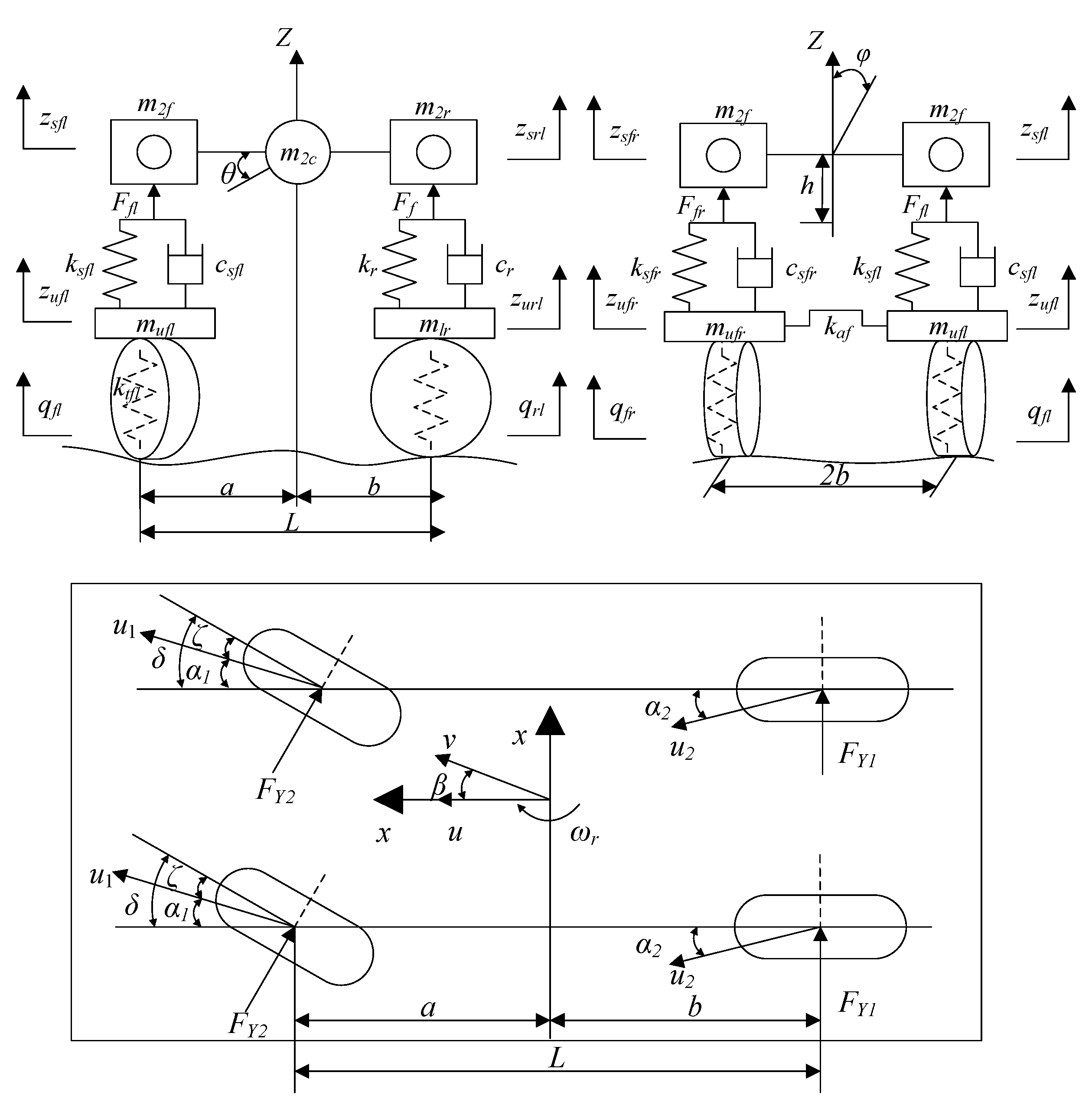
3.2. Mechanical Subsystem Model

The mechanical subsystem of P-ECHPS is mainly composed of the steering wheel-steering shaft model, steering screw-steering nut model, steering nut-rocker shaft fan model and rocker shaft toothed fan-rocker shaft model [17]. The models are as follows:
{ J s θ ¨ d + B c θ ˙ d + K c ( θ d θ lg ) = T d J lg θ ¨ lg + B lg θ ˙ lg = K c ( θ d θ lg ) F L M lm X ¨ lm + B lm X ˙ lm = F + F z F cs J cs θ ¨ cs + B cs θ ˙ cs = F cs r cs T p
where JS is the steering wheel-steering column equivalent moment of inertia, θd is the rotation angle of the steering wheel, Bc is the steering column viscous damping, Kc is the torsion bar stiffness, θ1g is the rotation angle of steeling screw, Td is the steering wheel torque, L is the center distance of screw force, J1g is the steering screw equivalent moment of inertia, F is the steering screw axial force, B1g is the viscous damping coefficient of steering screw-worm gear, M1m is the mass of the steer nut, θcs is the angle of gear sector, B1m is the damping coefficient of power cylinder, X1m is the displacement of steer nut, Fz is the power provided by the hydraulic system, Fcs is the force of gear sector on the rocker arms, Jcs is the gear sector equivalent moment of inertia, Bcs is the viscous damping coefficient of gear sector, rcs is the pitch radius of gear sector, Tp is steering resistance moment.

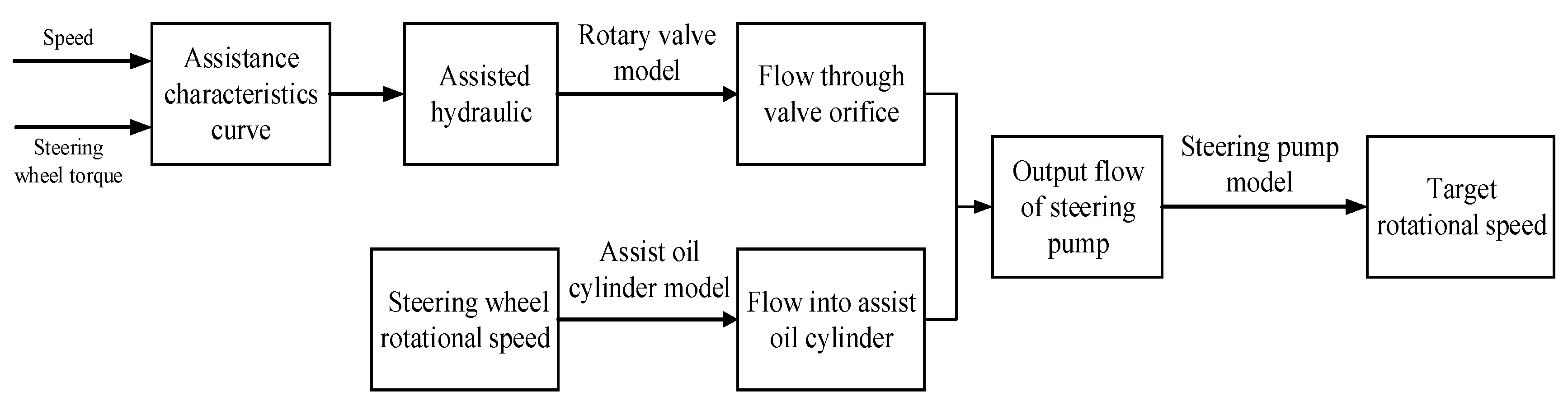
3.3. Hydraulic Subsystem Model

The hydraulic subsystem in P-ECHPS is mainly composed of the rotary valve, steering pump and assist oil cylinder. The power provided by the hydraulic system is affected by the flow area of the rotary valve port and the calculation formula is given by
A i = { W 1 L 1 2 + R 2 2 L 1 R c o s ( α 1 φ ) + ( W 2 W 1 ) ( A 2 π φ R 180 ) φ = 0 ~ α 1 W 1 ( L 2 2 + R 2 + 2 L 2 R c o s ( φ + β ) R 1 ) φ = α 1 ~ α 2
where A1 is the width of the edge, B is the width of the valve port, W1 is axial length of the edge, W2 is the axial length of the pre-opened play, R is the radius of valve cores, R1 is the radius of the edge, α1 is the angle of pre-opened, α2 is both the cutting edge angle and the pre-opened angle, L1 is the length of the edge for the cutting edge to the center of the spool, L2 is the arc eccentricity of edge, β is the corner of the valve groove.
According to the basic knowledge of hydraulic transmission [18], the mathematical model of the steering pump and the power cylinder can be expressed as
Q = n b V p
Q L = A p v p + C i Δ p
where Q is the output flow of steering pump, nb is the speed of steering pump, Vp is the displacement of steering pump, QL is the flow of the rotary valve into the hydraulic cylinder, Ap is effective area of the piston, Vp is the speed of piston movement, Ci is the leakage coefficient, ∆p is the pressure difference between the two ends of the power cylinder.

3.4. Automobile Dynamics Model

As shown in Figure 6, the three-degree-of-freedom automobile dynamic model including lateral, roll, and yaw is adopted.
The mathematical model [19,20] is as follows:
{ I z w ˙ r I xz φ ¨ = 2 a K 1 δ 1 2 b K 2 δ 2 m u ( w r + β ˙ ) + m s h φ ¨ = 2 K 1 δ 1 + 2 K 2 δ 2 I x φ ¨ + m s h u ( w r + β ˙ ) I xz w ˙ r = ( d 1 + d 2 ) φ ˙ ( c 1 + c 2 m s h g ) φ
where Ix and Iz are the moment of inertia with respect to the longitudinal axle and vertical axle, respectively, Wr is the yaw rate, m, ms are complete automobile mass and sprung mass, Ixz is the inertial product of sprung mass around z and x axis, K1, K2 are, respectively, the front stiffness of front and rear wheels, a, b are the centroid distance to the front and rear axle, δ1, δ2 represent the side-slip angle of front and rear wheel, u is the automobile lateral velocity, β is the side-slip angle, h is the rolling arm, φ is the automobile roll angle, d1, d2 are the damping coefficient of the front and rear suspension roll angle, c1, c2 represent, respectively, the rolling angle stiffness of the front and rear suspension.

3.5. Tire Model and Steering Resistance Torque Model

In the tire modeling process, only the side slip condition was studied. At this time, the tire cornering stiffness is considered to be linear, and the mathematical model can be expressed as
{ F c = K 1 δ 1 T h = F c d
where Fc is the tire lateral forces bias, d is the tire towing, Th is the aligning torque.
According to the geometric relationship, the formula for calculating the side angle of the front wheel is:
δ 1 = β + a u w r δ E 1 φ
where E1 is the front suspension roll steering coefficient, δ is the front wheel corner.
The input torque of the steering system is mostly used to overcome the aligning torque generated by the interaction between the road surface and the steering wheel [21], ignoring the steering inertia force moment and the steering friction torque, and the steering resisting torque Tp can be obtained. The calculation formula can be written as
T p = K 1 d ( β + a u w r δ E 1 φ )

4. P-ECHPS System Controller Design

4.1. Terminal Sliding Mode Control

4.1.1. Terminal Sliding Mode

The switching function of the Terminal Sliding Mode (TSM) can be expressed by the following equation:
s = x ˙ + β x q p = 0
In the formula, β’ > 0; p’ and q’ are both positive odd numbers, and 1 < p’/q’ < 2; system state x ∈ R1. to is the time taken to reach equilibrium x = 0 from the initial state x(0) ≠ 0, which can be solved by solving the Equation (14) to determine. The actual solution:
t o = p β ( p q ) | x ( 0 ) | ( p q ) / p
Consider the Jacobian determinant (14) near the equilibrium zero:
J = x ˙ x = β q p x ( 1 q / p )
J is regarded as the eigenvalue of the first order approximate matrix.
J→−∞ where x→0+
It can be seen that the eigenvalues at the equilibrium zero tend to be negative infinite. If |J|→∞ does not satisfy the Lipschitz condition, it can guarantee that the existence and uniqueness of solutions of differential equations at the origin and J is singular at the origin. Only under the condition of not satisfying Lipschitz condition, the system state can guarantee convergence in finite time.

4.1.2. Nonsingular Terminal Sliding Mode

Although TSM has many advantages, such as excellent responsiveness, limited time convergence and high control accuracy, it is found that singular phenomena inevitably occur in the actual use of TSM. In order to avoid singular phenomena, the Non-singular Terminal Sliding Mode (NTSM) emerged. The switching function of NTSM is as follows [22]:
s = x + 1 β x ˙ p q = 0
In the formula, β” > 0; p” and q” are both positive odd numbers, and 1 < p”/q” <2. to is the time taken to reach equilibrium x1(to) = 0 from the initial state x1(0), which can be solved by solving Equation (17). The actual solution:
t o = p β ( p q ) x ( 0 ) ( p q ) / p
Like TSM, NTSM can converge in a limited time.

4.1.3. Fast Terminal Sliding Mode

Although the control performance of TSM is better than that of SMC, it is not the best in terms of convergence time. As the distance between system state x and equilibrium zero becomes longer and longer, the convergence speed of TSM becomes slower. To overcome this shortcoming, the Fast Terminal Sliding Mode (FTSM) is proposed. The switching function of FTSM can be expressed as follows [22]:
s = x ˙ + α x + β x p q = 0
In the formula, α”’ > 0, β”’ > 0; p”’ and q”’ are both positive odd numbers, and 1 < p”’/q”’ < 2.
The solution of Equation (19) is obtained as follows:
t 0 = p α ( p q ) ln α x ( 0 ) ( p q ) / p + β β
Consider the Jacobian determinant (19) near the equilibrium zero:
J = x ˙ x = α β q p x ( 1 q / p )
Similarly, J is regarded as the eigenvalue of the first order approximate matrix.
J→−∞ where x→0+
So, set the parameters (α”’, β”’, p”’, q”’) appropriately to ensure that the finite time converges to zero, when it is on the sliding surface; the actual solution:
x ˙ = α x β x q p
If the distance between the system state and the equilibrium zeros is getting farther and farther, the convergence time depends on x ˙ = β x q / p ; If the distance between the system state and the equilibrium zero is getting closer and closer, the convergence time depends on x ˙ = α x , where the x exponent decays rapidly [23]. In this way, the system state can converge to zero quickly and accurately.

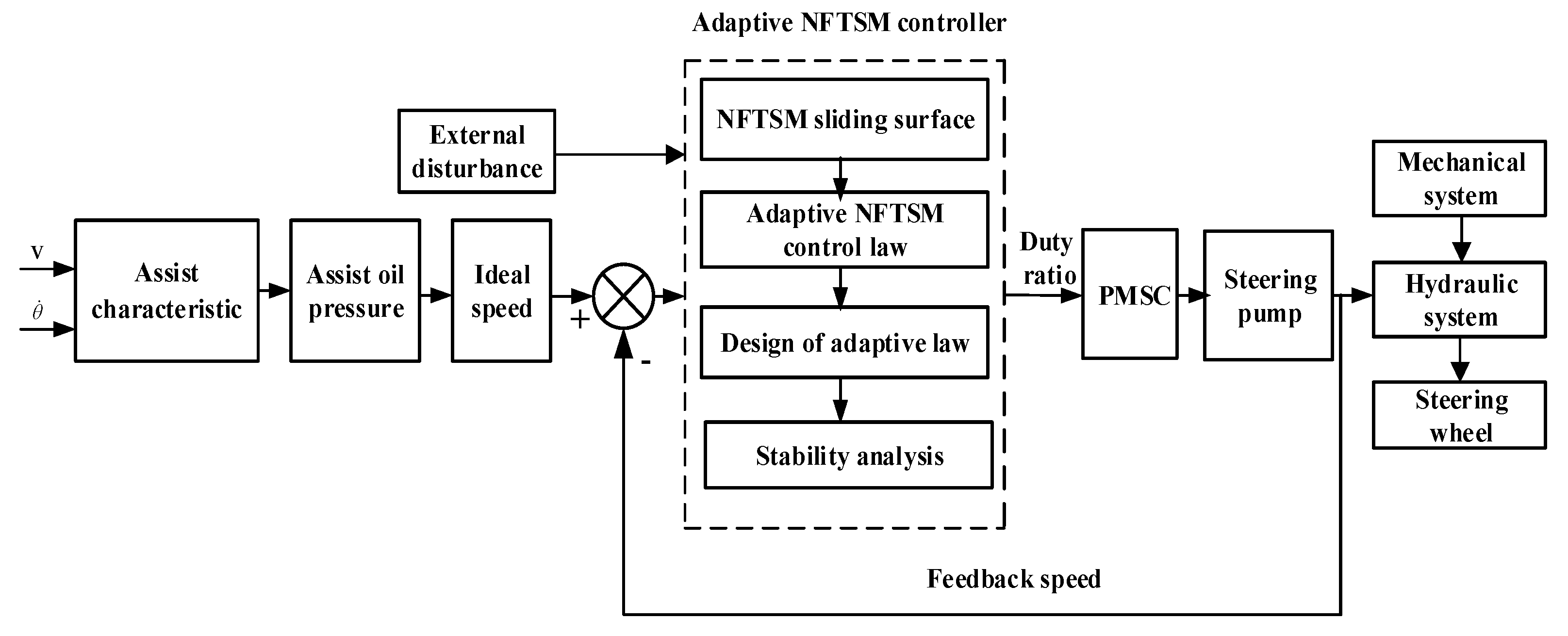
4.2. P-ECHPS System Control Strategy

In order to obtain good control effects and provide the automobile with the best power for each working condition, it is necessary to select a good algorithm to control P-ECHPS.
The whole system of P-ECHPS has many characteristics such as the rapid response requirements, multivariable and strong non-linearity. There are also many inevitably uncertain factors in the working process, such as fluctuations in the engine speed, crosswind, and random forces from the road surface, etc.
The NFTSM algorithm combines the advantages of both NTSM and FTSM, overcoming the shortcomings of the SMC system state failure to converge to zero in finite time, avoiding the singular phenomenon of TSM input, and can improve the shortcomings of the NTSM algorithm but cannot guarantee fast global convergence, so this paper proposes an adaptive NFTSM algorithm. By precisely controlling the inter rotor speed of the PMSC, approved power control is achieved for the entire P-ECHPS system. Figure 7 is a block diagram of the P-ECHPS adaptive NFTSM algorithm.

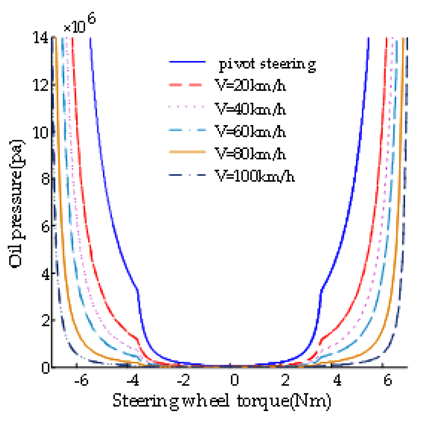
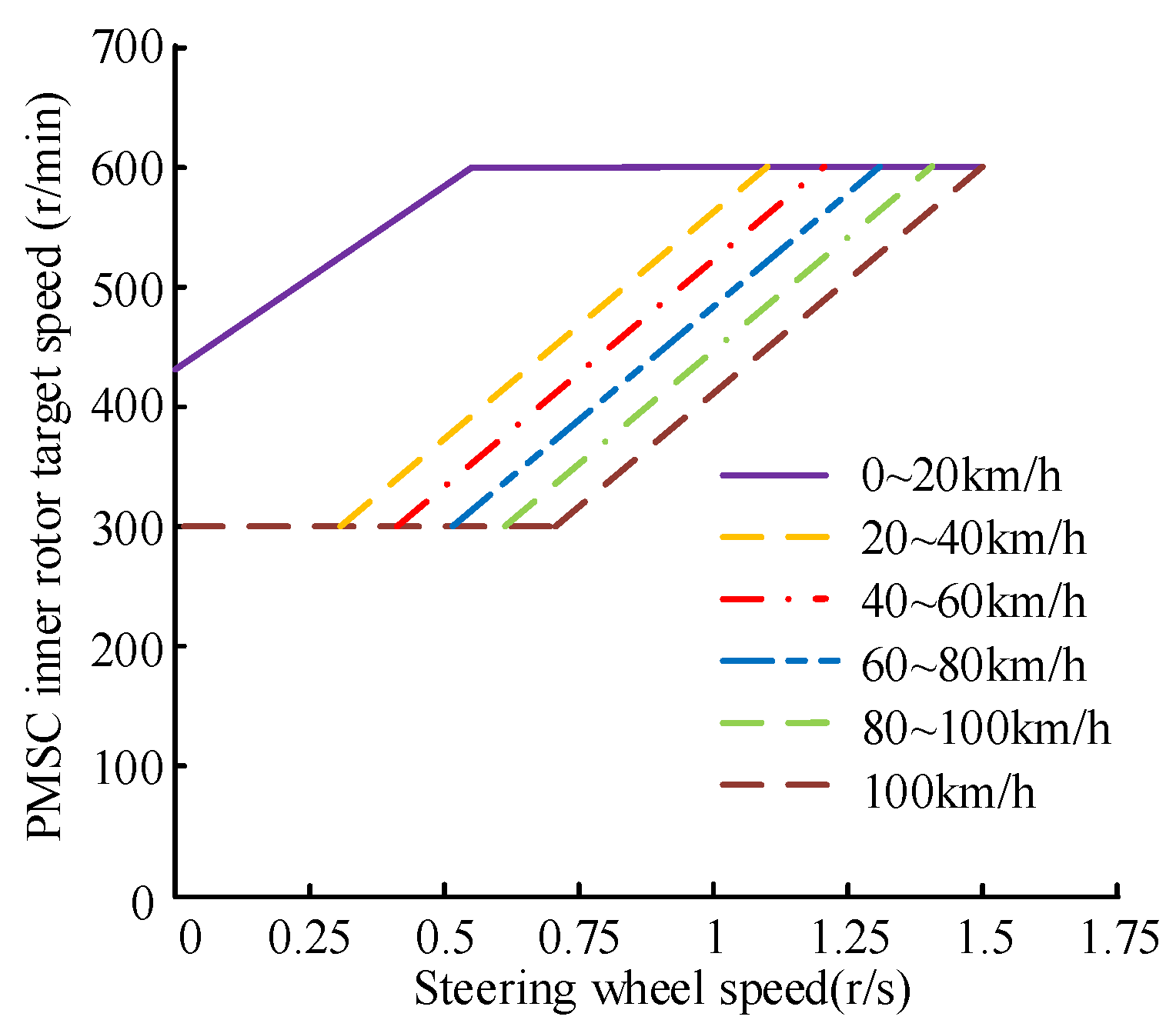
4.3. Assist Characteristics and Ideal Speed

The assist characteristics are closely related to the maneuverability and safety of the automobile. The ideal assist characteristics should be variable with the speed of the automobile. The specific requirements are as follows: the automobile should provide greater power in the in-situ or low-speed steering conditions to make the steering lighter and improve maneuver stability. With the increase in speed, the power provided should gradually decrease; especially under high-speed conditions, relatively minimum assistance should be provided to give the driver a better “road feel” to ensure driving safety.
The concrete design methods are as follows: Firstly, the driver’s preferred steering wheel torque and the automobile steering resistance torque are achieved at different automobile speeds. Secondly, the automobile steering resistance torque is equivalent to the steering wheel resistance torque and compensates for the difference between the steering wheel resistance torque and the driver’s preferred steering wheel torque. The assist torque required by the system at different speeds is obtained. Finally, according to the assist characteristic curve of the P-ECHPS system, six characteristic automobile speeds were selected, and the variable assist characteristic curve as shown in Figure 8 was designed.
The target speed range of the inner rotor (steering pump) of the PMSC is [300, 600] r/min, but in order to provide suitable assistance under various working conditions of P-ECHPS, it is necessary to determine the target speed of the PMSC inner rotor during the driving process in each working condition. Figure 9 shows the specific calculation process.
The PMSC inner rotor target speed curve shown in Figure 10 is made by calculation.

4.4. Adaptive NFTSM Controller Design

4.4.1. Error State Equation of the rotational Speed

The state variables of the controlled system E = (e1, e2) are defined, among them
{ e 1 = ω 2 ω d e 2 = ω ˙ 2 ω ˙ d
where ωd is the target angular velocity, equal to the target speed multiplied by π/30, rad/s, e1 is the speed error, e2 is the derivative of speed error.
The state equation of the rotational speed error derived from the simultaneous (1) can be expressed as:
{ e ˙ 1 = e 2 e ˙ 2 = F ( x ) + G ( x ) u + d ( t )
where F ( x ) = C m k + ( L d C + R ) F 2 L d J 2 ω 2 ( L d C + R ) J 2 + L d F 2 L d J 2 ω ˙ 2 ( L d C + R ) T L + L d T ˙ L L d J 2 , u is the control quantity (duty cycle), d ( t ) = ω ¨ d , G ( x ) = L d C ( J 2 ω ˙ 2 + T L + F 2 ω 2 ) L d J 2 .
Considering the entire system of P-ECHPS has many uncertainties, e ˙ 2 expressed as follows:
e ˙ 2 = ( F ( x ) + Δ F ) + ( G ( x ) + Δ G ) u + ( d ( t ) + Δ d )
where ∆F, ∆G and ∆d are, respectively, uncertainties of the corresponding items F(x), G(x) and G(x), these uncertainties are bounded.
Record the total uncertainty and external disturbances as h(t), then:
h ( t ) = Δ F + Δ G u + d ( t ) + Δ d
Therefore, the state equation can be obtained as:
{ e ˙ 1 = e 2 e ˙ 2 = F ( x ) + G ( x ) u + h ( t )
where h(t) is bounded, assume |h(t)| ≤ lh; lh is the interference maximum and is a constant greater than zero.

4.4.2. Adaptive NFTSM Control Strategy

Define the NFTSM sliding mode switching function [24]:
s = e 1 + A e 1 G H + B e 2 p 2 q 2
where A, B > 0, G, H, p2 and q2 are positive odd integers, 1 < p2/q2 < 2, G/H > p2/q2.
When the system state is far from the balance point, e1 is the higher order term and makes the control amount larger, the system convergence speed becomes faster, and the convergence speed is higher than the ordinary NTSM algorithm; when the system state is close to the equilibrium point, at this time e1, e2 are both tend to be close to 0, e1 the higher order term is smaller and negligible, and the convergence speed is similar to the NTSM algorithm, so the NFTSM sliding mode surface can ensure the global convergence of the control system [25].
Use lh estimate l ^ h instead of lh at the same time; using the exponential approach strategy, the adaptive NFTSM algorithm can be obtained as follows:
u = 1 G ( x ) [ F ( x ) + 1 B q 2 p 2 e 2 2 p 2 q 2 ( 1 + A G H e 1 G H 1 ) + ( l ^ h + η 2 ) sgn ( s ) + k 3 s ]
where η2 > 0, k3 > 0.
The adaptive strategy is defined as follows:
l ^ ˙ h = n B p 2 q 2 e 2 p 2 q 2 1 | s |
where n is an adjustable parameter.
The Lyapunov function is taken to perform stability analysis:
V = 1 2 s 2 + 1 2 n l ˜ h 2
where, l ˜ h = l h l ^ h .
Take a derivative with respect to Equation (31)
V ˙ = s s ˙ 1 n l ˜ h l ^ ˙ h = s ( e 2 + A G H e 1 G H 1 e 2 + B p 2 q 2 e 2 p 2 q 2 1 e 2 ) 1 n l ˜ h l ^ ˙ h = s B p 2 q 2 e 2 p 2 q 2 1 [ k 3 s + ( l ˜ h η 2 ) sgn ( s ) ] 1 n l ˜ h l ^ ˙ h B p 2 q 2 e 2 p 2 q 2 1 ( k 3 s 2 + η 2 | s | )
Because we can determine e 2 p 2 q 2 1 0 from 1 < p2/q2 < 2, and can also determine V ≤ 0 from B > 0, η2 > 0, k3 > 0. When e2 ≠ 0, V < 0, according to the Lyapunov stability theorem, it can be known that the closed-loop control system is asymptotically stable and will converge to zero in finite time.
Controller parameters: A = 1, B = 0.0052, G = 9, H = 5, n = 1, p2 = 7, q2 = 5, η2 = 48, k3 = 21,000.

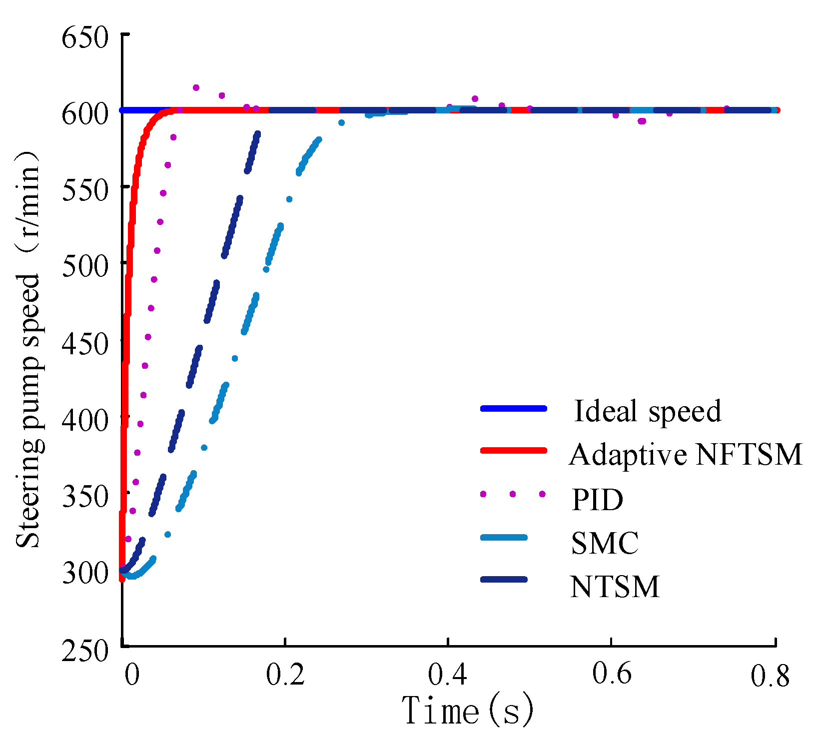
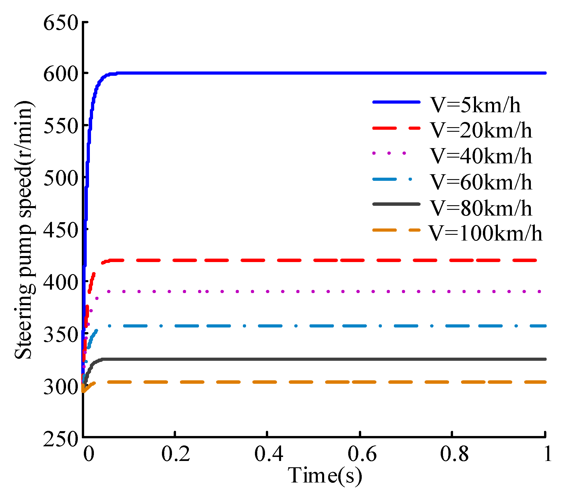
5. Simulation Analysis

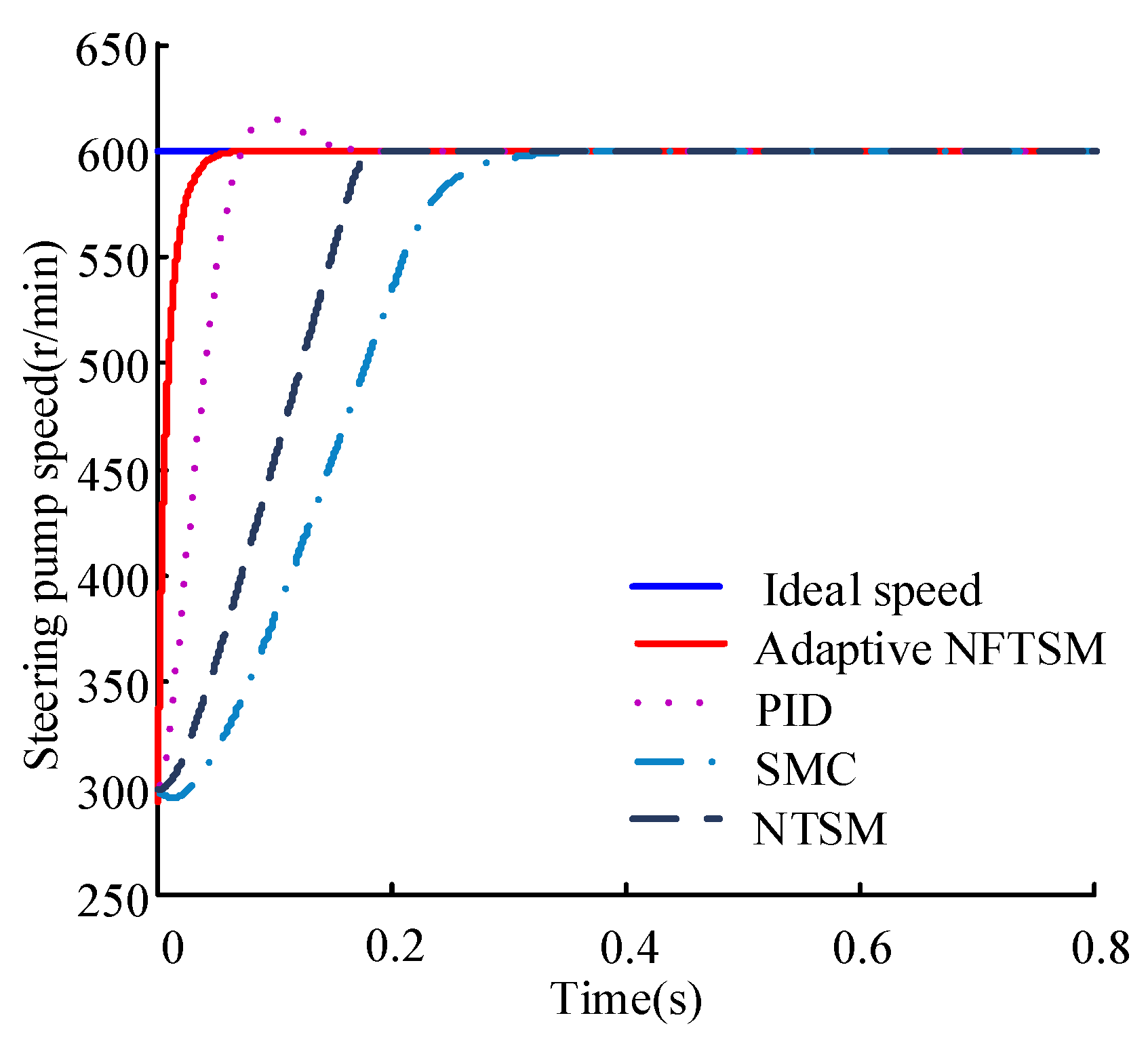
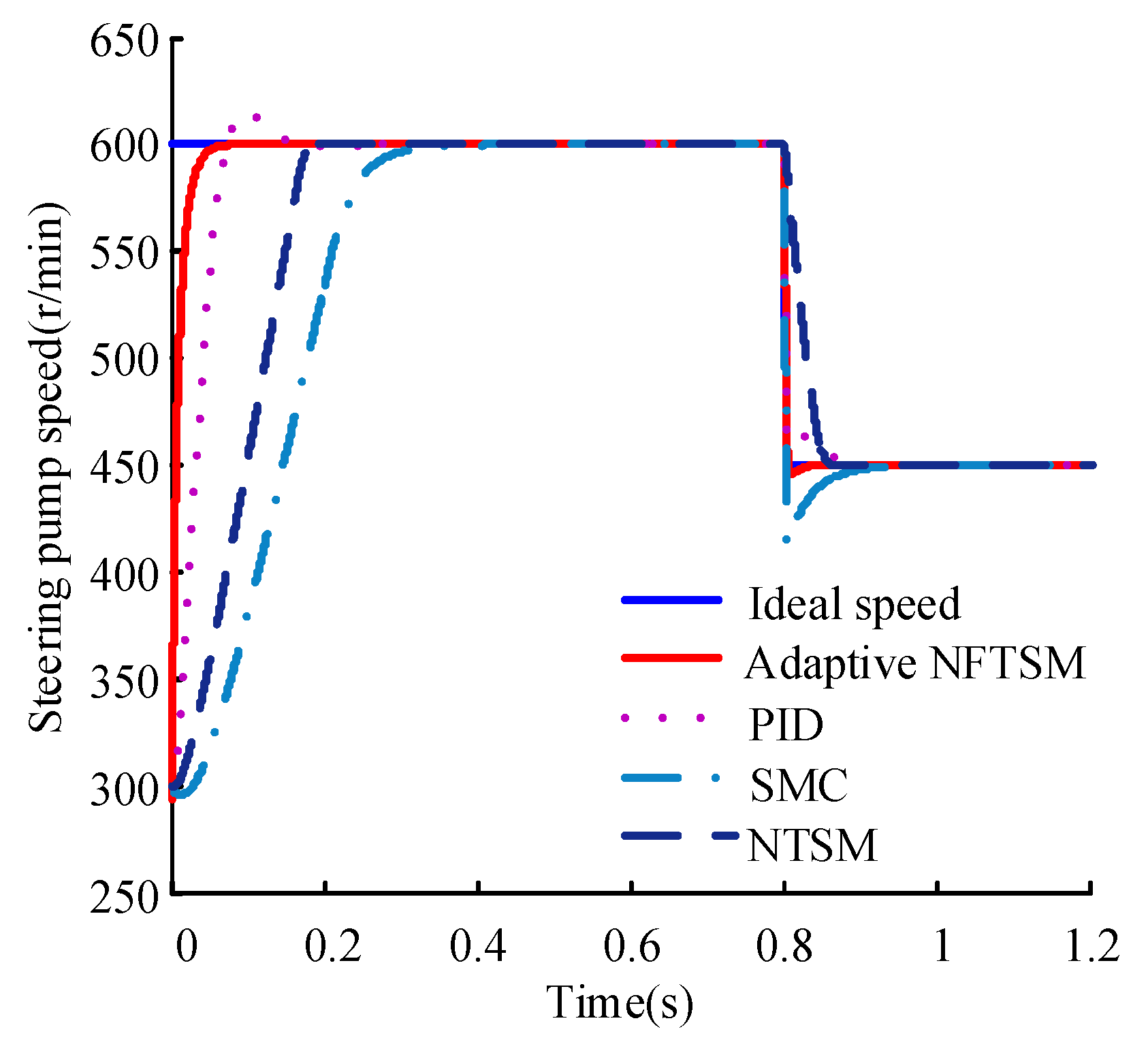
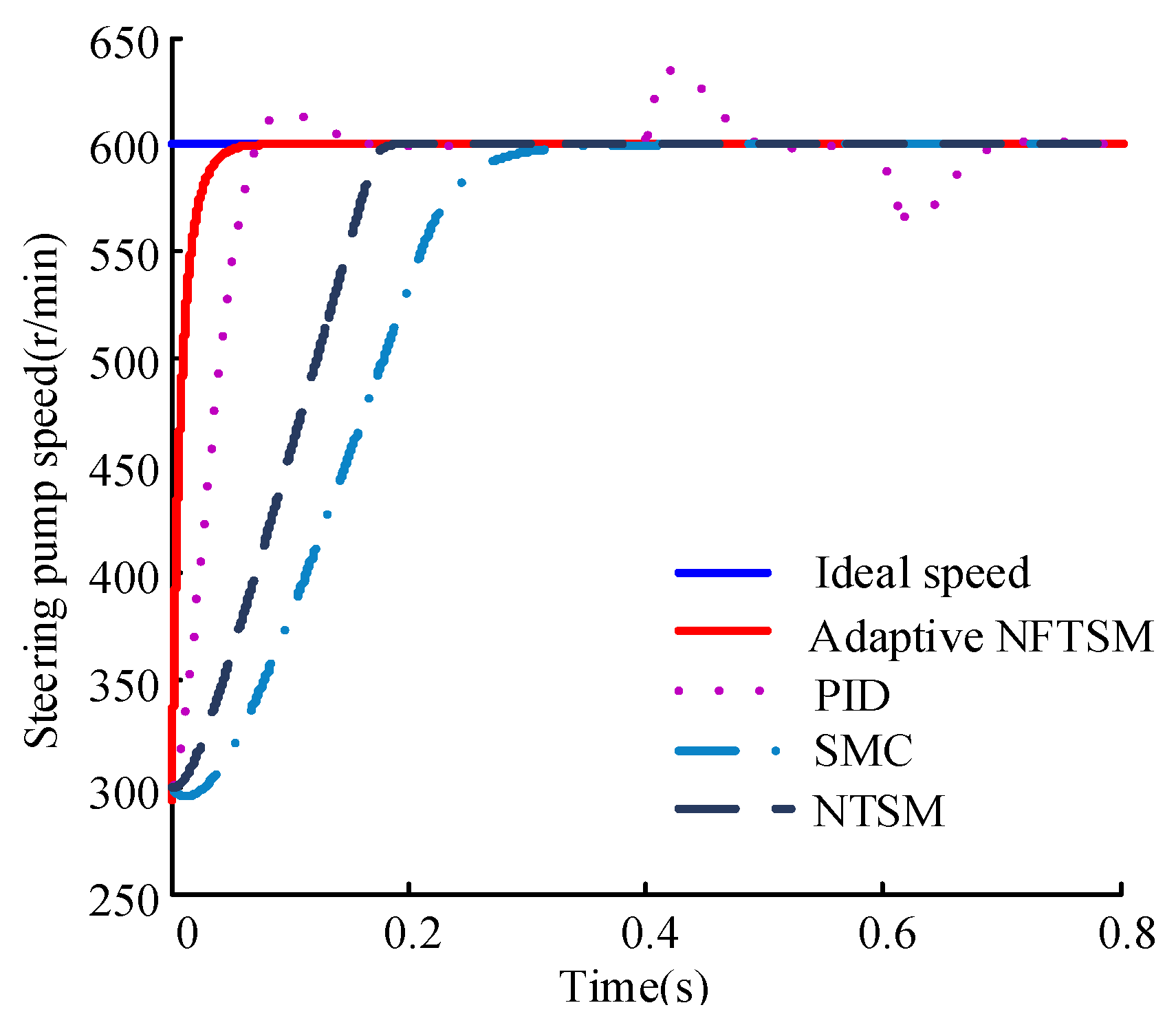
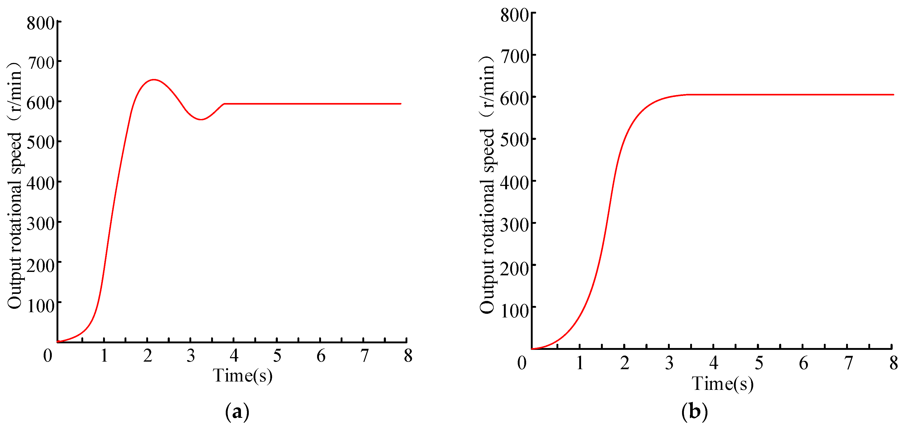
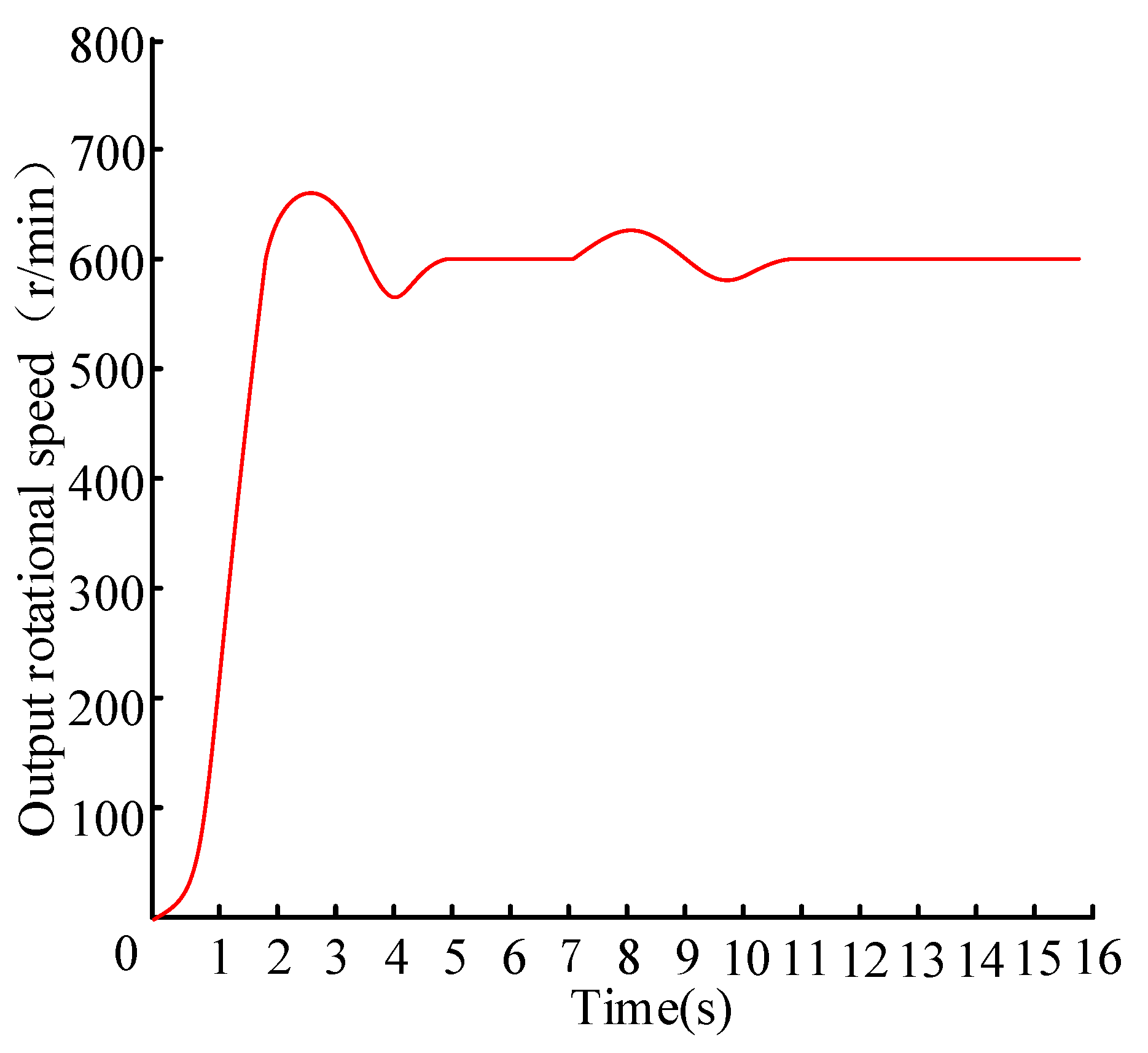
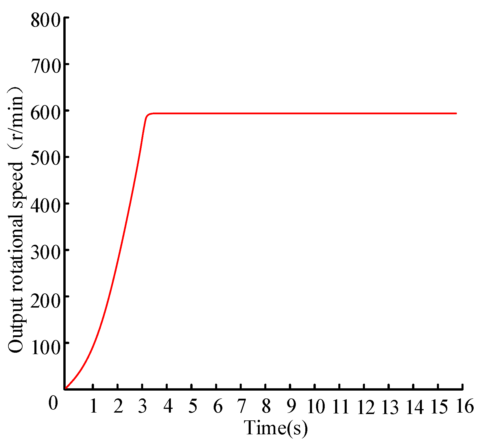
5.1. PMSC Speed Control System Simulation

According to the designed controller, Matlab/Simulink (R2016a) was used to build the speed control of PMSC for four control system models: PID, SMC, NTSM and adaptive NFTSM. Through simulation, the control effects of adaptive NFTSM and other three algorithms are compared and analyzed.
The simulation condition was set to in-situ steering while assuming a steering wheel speed ωo ≥ 0.5 r/s; according to Figure 10, the target speed is 600 r/min. Refer to the engine speed under idle conditions. The input speed can be set to 700 r/min and the load torque, according to the recommended values in reference [26], is set to 40 Nm. The comparison result between the adaptive NFTSM algorithm and the other three algorithms on the PMSC speed control is obtained, as shown in Figure 11.
Figure 12 is, in this simulated working condition, the time comparison (response time) chart of when the actual torque reaches the stable value under different control methods supposing that the target speed is adjusted from 600 r/min to 300 r/min at 0.8 s; if other values are constant, the speed response of the target speed change can be obtained, as shown in Figure 13. Assuming that the input speed changes from 700 r/min to 1200 r/min at 0.4 s, and then back to 700 r/min at 0.6 s after stabilization. Other conditions remain unchanged, and Figure 14 shows the speed response of the input speed changes. Figure 15 shows that the rotational speed response when the load torque changes under the following conditions: the load torque is abrupt change at 0.4 s, falling from 40 Nm to 30 Nm and adjust to 40 Nm at 0.6 s after stability and the other conditions are the same.
Analysis of simulation results:
(1) From Figure 11, it appears that the four control algorithms of adaptive NFTSM, PID, SMC, and NTSM can make the rotor speed of the PMSC track the target speed. Among them, due to poor dynamic performance of PID, PID control has overshoot, and the other three control algorithms have no overshoot. For convergence time, adaptive NFTSM, NTSM and SMC need about 0.06 s, 0.18 s and 0.38 s, respectively, and the convergence rate is compared with adaptive NFTSM and NTSM, SMC; the convergence speed is increased by 66.7% and 84.2% respectively, and the control performance is relatively optimal.
(2) Figure 12. depicts that the actual output torque response is the same as the rotational speed response, and the adaptive NFTSM algorithm performance is relatively optimal. Figure 13. depicts the adaptive NFTSM algorithm that allows the PMSC inner rotor speed to be adjusted and tracked to the new target speed as soon as the target speed changes.
(3) Figure 14 and Figure 15. depict that in the case where the input speed or the load torque suddenly changes, the adaptive NFTSM algorithm’s anti-interference ability is better than the PID algorithm’s.
In summary, the adaptive NFTSM algorithm method has the fastest convergence speed, strong robustness and good control performance for the PMSC inner rotor speed, which can meet the fast response requirements of the P-ECHPS whole system and ensure the stability of the P-ECHPS control system.

5.2. P-ECHPS System Assist Characteristic Simulation

According to the model of each part of the P-ECHPS system, the adaptive NFTSM control system model is added, and the P-ECHPS system automobile simulation model is built in Matlab/Simulink, as shown in Figure 16. The simulation parameters refer to the bus of SLK6118.
Firstly, 5 km/h is selected as the first characteristic automobile speed (instead of the in-situ steering condition), set the steering wheel speed to 0.5 r/s, and the steering wheel torque adopts the slope signal with a slope of 10 Nm/s. Keep the speed constant when it reaches 5 km/h, the simulation is carried out to obtain the steering pump speed curve and the corresponding assist oil pressure response curve at the speed of 5 km/h. Secondly, in the range of 20~100 km/h, with 20 km/h as an interval, select 5 characteristic automobile speeds, and set the slope signals to 5.3 Nm, 5.6 Nm, 5.9 Nm, 6.2 Nm, respectively; 6.5 Nm remains unchanged, and the comprehensive simulation results are shown in Figure 17 and Figure 18.
Figure 17 and Figure 18 show that with the adaptive NFTSM algorithm, the automobile speed is gradually increased, the inner rotor speed of the PMSC and the speed of steering pump will gradually decrease, and the assist oil pressure generated by the steering system will gradually decrease. The actual assist oil pressure is in accordance with the assist characteristic curve designed above, showing that the P-ECHPS adaptive NFTSM algorithm can realize the variable assist characteristic of P-ECHPS.

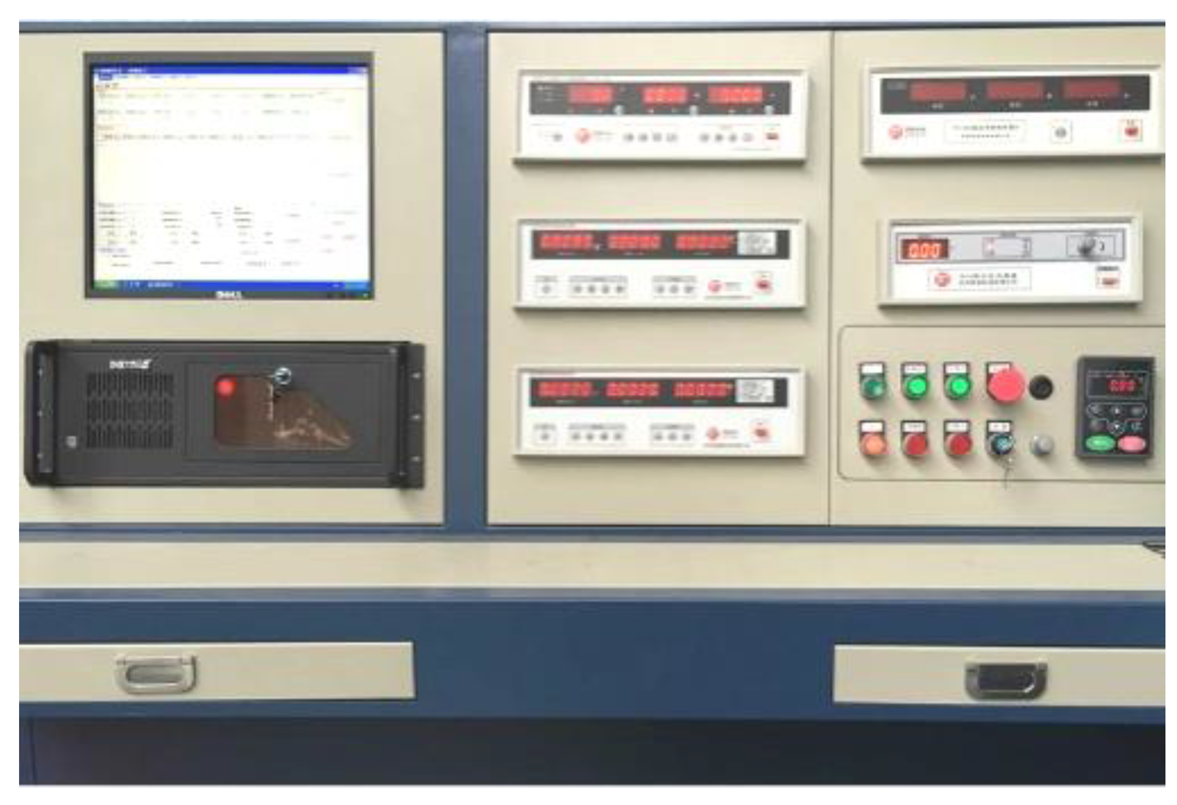
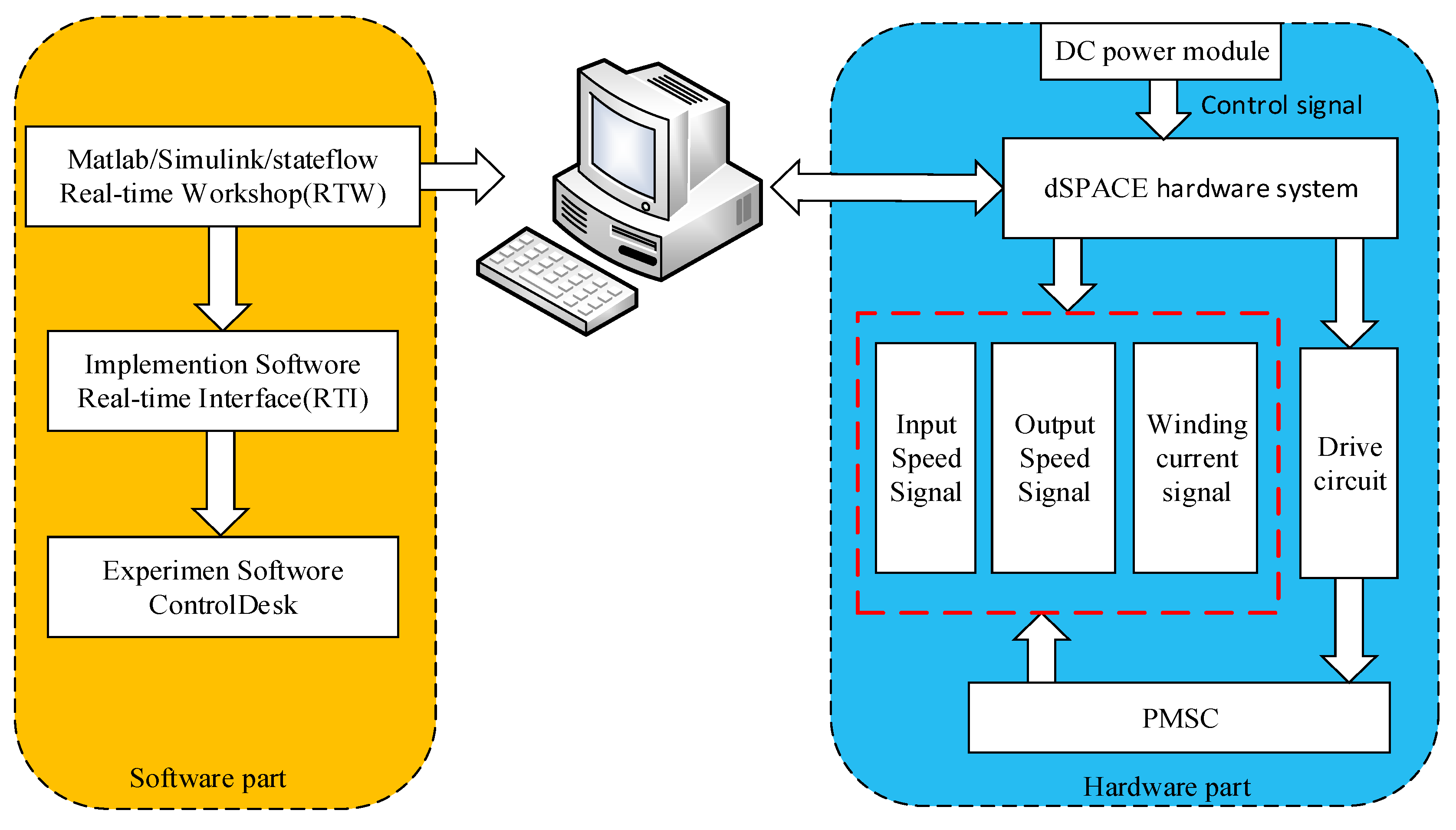
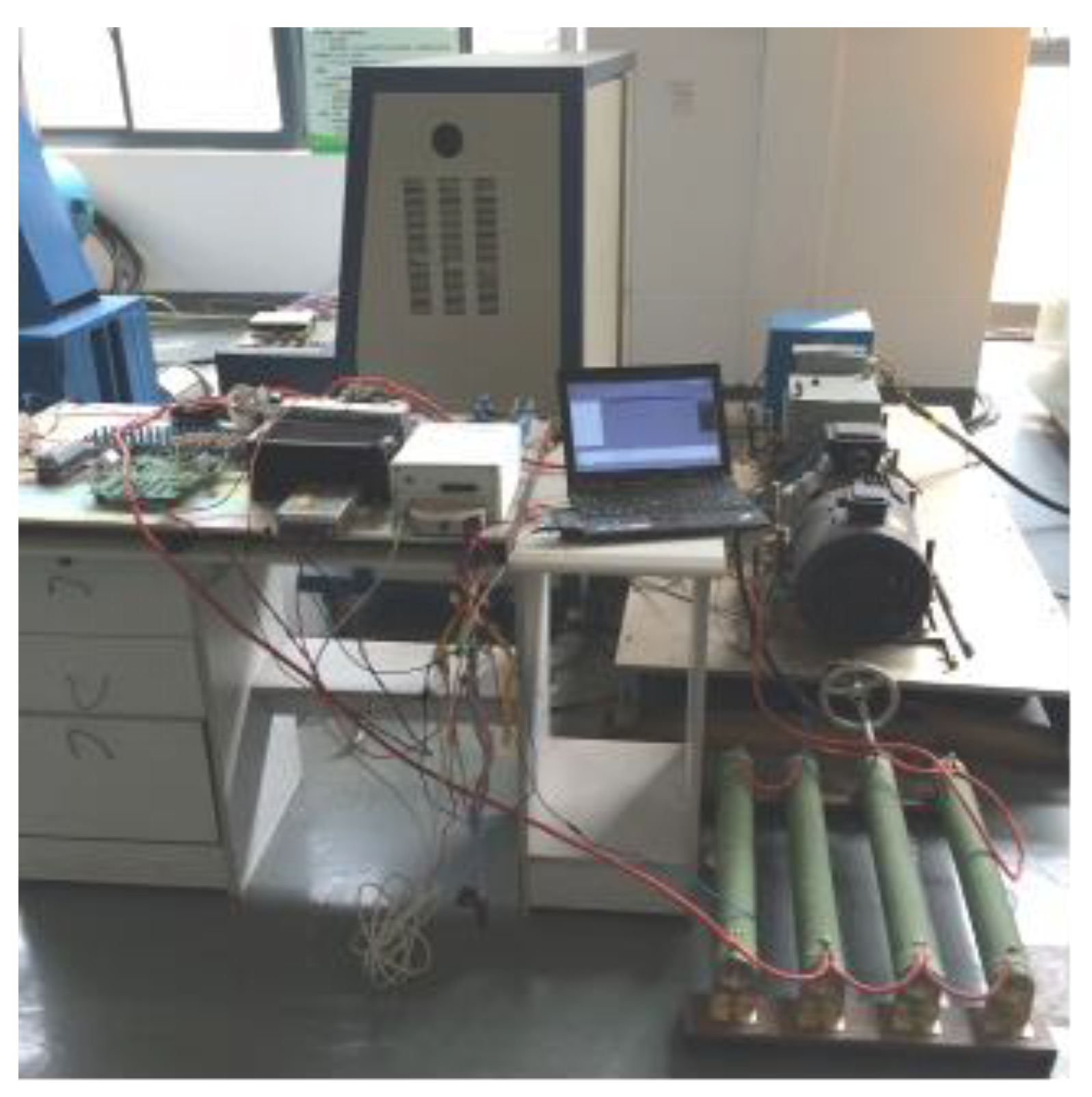
6. PMSC Rapid Control Prototype Test

In order to verify the effect of the adaptive NFTSM algorithm, a rapid control prototype test based on dSPACE was performed on the PMSC speed regulation. Figure 19 is a PMSC rapid control prototype test platform built, including hardware and software. The hardware part includes the dSPACE powered by DC power. With the help of the PMSC test bench, MicroAutobox was used to collect two speed sensors including input and output and winding current sensor signal of the PMSC test bench. dSPACE is calculated by the control algorithm, and control signal PWM was outputted to drive the drive circuit (The drive circuit is provided by Magnetic Valley Technology Co. Ltd.) to drive the IGBT; the inner rotor speed in the PMSC can be adjusted. The PWM and the rotor speed of the PMSC are both different, and finally the P-ECHPS variable assist characteristic can be realized.
The actual test bench is shown in Figure 20.
The test compares the inner rotor speed response of the PMSC adopting the adaptive NFTSM algorithm and PID algorithm. Firstly, the interference-free test is carried out. The real-time simulation condition is P-ECHPS in-situ steering. At this time, the target output speed is 600 r/min. In the real-time simulation model, the target speed is set to 600 r/min, while the load torque is set to 40 Nm, and then the test is carried out to set the variable frequency motor speed (that is the input speed) to 700 r/min. During the test, the Control Desk has the function of adjusting the parameters online, and the PID control parameters are adjusted in real time. Finally, the PMSC internal rotor speed response curve under PID control (Figure 21) and the PMSC inter rotor speed response curve under adaptive NFTSM control (Figure 22) can be obtained.
It can be seen from Figure 21. that PID has a good control effect under the condition that there is no interference in the system and parameters can be adjusted online in real time, but it is slightly inferior to the adaptive NFTSM algorithm; both can make the inner rotor speed of PMSC track fast to the target speed of 600 r/min and keep it steady. It takes more time to reach steady state than offline simulation due to the variable frequency motor takes a certain time from the start to the setting speed of 700 r/min.
Based on the above test without interference, the input speed is quickly adjusted from 700 r/min to 1000 r/min at 7 s. Other settings are maintained, and the inner rotor speed response curve of the PMSC in the PID control under interference (Figure 22) and PMSC inner rotor speed response curve under adaptive NFTSM algorithm (Figure 23) are obtained.
It can be seen from Figure 22 and Figure 23. that the PID control lacks the ability of disturbance rejection in the presence of interference, and the adaptive NFTSM algorithm can better resist the influence of the interference, so that the inner rotor speed in the PMSC can track the target speed 600 r/min fast and closely. This algorithm has good control effect without overshoot. The above test results show the validity of the adaptive NFTSM algorithm used in P-ECHPS and the correctness of offline simulation results.

7. Conclusions

A new steering system P-ECHPS suitable for medium and heavy duty commercial automobiles is proposed. The mathematical models of the speed control of the core transmission mechanism and the subsystem models are established. The adaptive NFTSM control strategy is used to control the system and the controller is designed. The PMSC speed regulation performance and the assist characteristics of system power are simulated. The results show that the designed controller has good control performance and can guarantee the global fast convergence of the closed-loop control system, so that the speed of the speed pump can be quickly tracked to the ideal speed. The NTSM and SMC have improved by nearly 66.7% and 84.2%, respectively, and have good anti-interference ability, which makes the heavy-duty automobile realize the variable assist characteristics well and meet the requirements of steering assist and road feeling. The rapid control prototype test of PMSC based on dSPACE is carried out. The experimental results also show that the adaptive NFTSM can quickly track the target speed of the inner rotor in the PMSC and has strong robustness. This experimental verifies the effectiveness of the adaptive NFTSM algorithm and the correctness of the off-line simulation results.

Author Contributions

G.G. and Q.S. conceived of and designed the method. G.G. and Q.S. performed the software simulation and analyzation. Q.S. and G.G. performed the experiments and analyzed the experimental data. Q.S. wrote the paper with the help of G.G. and H.J.

Funding

This work is financially supported by The National Natural Science Fund (No. 51275211 and No.51605199) and Natural Science Fund Project of Colleges in Jiangsu Province (No.14KJB580003).

Conflicts of Interest

The authors declare no conflict of interest.

References

  1. Baharom, M.B.; Hussain, K.; Day, A.J. Design of full electric power steering with enhanced performance over that of hydraulic power-assisted steering. Proc. Inst. Mech. Eng. Part D J. Automob. Eng. 2013, 227, 390–399. [Google Scholar] [CrossRef] [Green Version]
  2. Kozuma, F.; Arita, T.; Tsuda, H. Development of energy saving power steering. Proc. JFPS Int. Symp. Fluid Power 2005, 2005, 297–300. [Google Scholar] [CrossRef]
  3. Wolfgang, K.; Steffen, M.; Andreas, K. Mathematical modeling and nonlinear controller design for a novel electrohydraulic power-steering system. IEEE/ASME Trans. Mechatron. 2007, 12, 85–97. [Google Scholar]
  4. Murty, B.; Gopalakrishnan, S.; Namuduri, C.; Shoemaker, K. Magnetorheological coupling based hydraulic power steering: Low cost solution for fuel economy improvement. SAE Int. J. Passeng. Cars-Mech. Syst. 2009, 2, 219–228. [Google Scholar] [CrossRef]
  5. Wimmer, H.; Alsdorf, F. Modern front axle systems for city buses. ATZ Worldw. 2006, 108, 2–5. [Google Scholar] [CrossRef]
  6. Pawlak, A.M.; Graber, D.W.; Eckhardt, D.C. Magnetic power steering assist system-magnasteer. In 3rd Mobility. Technology Conference and Exhibit; SAE International: Warrendale, PA, USA, 1994. [Google Scholar]
  7. Zhang, K.M. Diagnosis and Detection of Electrically Controlled Power Steering System for Lingzhi Series Cars. Automot. Electr. Appl. 2004, 1, 36–37. [Google Scholar] [CrossRef]
  8. Xu, X.Y.; Lin, H. Integrated Position and Speed Design of Permanent Magnet Synchronous Motor Based on Dynamic Sliding Mode Control. TCES 2014, 29, 77–83. [Google Scholar] [CrossRef]
  9. Zak, M. Terminal Attractors in Neural Networks. Neural Netw. 1989, 2, 259–274. [Google Scholar] [CrossRef]
  10. Feng, Y.; Bao, W.; Yu, X.H. Design Method of Non-singular Terminal Sliding Mode Control System. Control Decis. 2002, 17, 194–198. [Google Scholar]
  11. Li, S.B.; Li, K.Q.; Wang, J.Q. Non-singular and Fast Terminal Sliding Mode Control Method. Inf. Control 2009, 38, 1–8. [Google Scholar]
  12. Li, H.; Dou, L.H.; Su, Z. Adaptive Non-singular fast terminal sliding mode control for electromechanical actuator. Int. J. Syst. Sci. 2013, 44, 401–415. [Google Scholar] [CrossRef]
  13. Zhao, L.; Jia, Y.M. Decentralized adaptive attitude synchronization control for spacecraft formation using Non-singular fast terminal sliding mode. Nonlinear Dyn. 2014, 78, 2779–2794. [Google Scholar] [CrossRef]
  14. Cheng, Y.; Lin, H. Non-singular fast terminal sliding mode position control of switched reluctance motor. J. Electr. Mach. Control 2012, 16, 78–82. [Google Scholar]
  15. Wang, W.B.; Su, H.S.; Zhang, X.C. Modeling and Simulation Analysis of Boost DC Converter Based on State Space Average Method. Electr. Drive Autom. 2013, 35, 29–32. [Google Scholar]
  16. Zhang, J.W.; Wang, B.S.; Wan, J. Analysis of Mechanical Characteristics of Chopper Cascade Speed Regulation System. Electr. Control Appl. 2010, 37, 25–29. [Google Scholar]
  17. Jiang, H.C.; Zhou, Z.L.; Qian, Y. Echps variable assist characteristics and control strategies for both maneuverability and energy conservation. J. Mech. Eng. 2015, 50, 17–26. [Google Scholar]
  18. Li, Z. Hydraulic Transmission; Mechanical Industry Press: Beijing, China, 2009. [Google Scholar]
  19. Ko, Y.E.; Song, C.K. Vehicle modeling with nonlinear tires for vehicle stability analysis. Int. J. Automot. Technol. 2010, 11, 339–344. [Google Scholar] [CrossRef]
  20. Jiang, H.B.; Tang, B.; Xu, Z.; Geng, G.Q. Electromagnetic and Torque Characteristics of Electromagnetic Slip Coupling Applied to Hydraulic Power Steering System for Heavy-Duty Vehicles. J. ASP. 2015, 12, 1069–1075. [Google Scholar]
  21. Wang, R.Q.; Zhou, Y.J.; Yin, P. Calculation of front wheel alignment and positive moment and steering force of automobile. J. Hunan Univ. Sci. Technol. 2010, 25, 42–46. [Google Scholar]
  22. Xia, J.; Hu, D.B. Research progress of terminal sliding mode control method. Chem. Autom. Instrum. 2011, 9, 1043–1047. [Google Scholar]
  23. Xiong, S.F.; Wang, W.H.; Wang, S. Nonsingular Fast Terminal Sliding Mode Guidance Law with Attack Angle Constraints. Control Theory Appl. 2014, 31, 269–278. [Google Scholar]
  24. Li, S.B.; Li, K.Q.; Wang, J.Q. Non-singular fast terminal sliding mode control method and its follow-up control application. Control Theory Appl. 2010, 27, 543–550. [Google Scholar]
  25. Zhang, X.G.; Zhao, K.; Sun, L. Mixed-non-singular terminal sliding mode variable structure control of permanent magnet synchronous motor. Proc. CSEE 2011, 31, 116–122. [Google Scholar]
  26. Geng, G.Q.; Miao, L.D.; Li, Q. According to the recommended values in reference Design Method of Electric Hydraulic Power Steering System. Res. Agric. Mech. 2006, 6, 207–210. [Google Scholar]
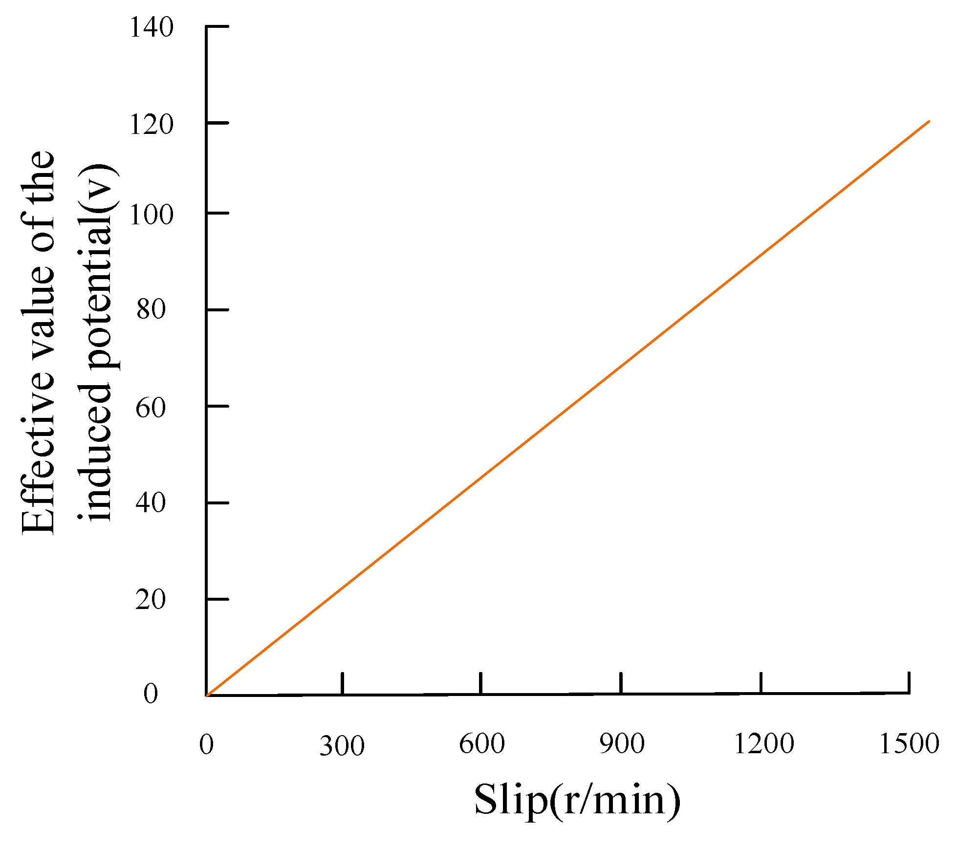
Figure 1. Composition diagram of P-ECHPS.
Energies 12 01739 g001
Figure 2. Structure diagram of PMSC.
Energies 12 01739 g002
Figure 3. Boost speed control circuit of IGBT.
Energies 12 01739 g003
Figure 4. Test bench of PMSC.
Energies 12 01739 g004
Figure 5. Relationship between the effective value of induced potential and slip.
Energies 12 01739 g005
Figure 6. Automobile dynamic model with three degrees of freedom.
Energies 12 01739 g006
Figure 7. Control Strategy diagram of P-ECHPS.
Energies 12 01739 g007
Figure 8. Ideal assist characteristic curve of P-ECHPS.
Energies 12 01739 g008
Figure 9. Calculation of PMSC inner rotor target speed.
Energies 12 01739 g009
Figure 10. The diagram of PMSC inner rotor target speed.
Energies 12 01739 g010
Figure 11. Speed response when input speed is fixed.
Energies 12 01739 g011
Figure 12. Steering pump speed response when input speed is fixed.
Energies 12 01739 g012
Figure 13. Speed response when target speed is changed.
Energies 12 01739 g013
Figure 14. Speed response when input speed is changed.
Energies 12 01739 g014
Figure 15. Speed response when load torque is changed.
Energies 12 01739 g015
Figure 16. Automobile simulation model of P-ECHPS.
Energies 12 01739 g016
Figure 17. Graph of steering pump speed at different speeds.
Energies 12 01739 g017
Figure 18. Graph of assist oil pressure at different speeds.
Energies 12 01739 g018
Figure 19. The rapid control prototype test platform of PMSC.
Energies 12 01739 g019
Figure 20. The rapid control prototype test physical map of PMSC.
Energies 12 01739 g020
Figure 21. Comparison and analysis of control results under different condition of PMSC speed response: (a) PID control; (b) adaptive NFTSM control.
Energies 12 01739 g021
Figure 22. PMSC speed response for the PID algorithm.
Energies 12 01739 g022
Figure 23. PMSC speed response for the adaptive NFTSM algorithm.
Energies 12 01739 g023
Table 1. Effective value of induced potential.
Slip /r/min100300500700900110013001500
Induced Potential rms /v8.124.340.956.873.489.5106.2122.3
Table 2. Speed regulation model parameters of PMSC.
ParameterNumerical Value
Winding resistance R0.5
Inductance Ld/H3 × 10−4
Capacitance C/μF4
Electromagnetic torque coefficient Cm1.82
Inner rotor damping coefficient F2/Nm·s/rad0.02
Inner rotor moment of inertia J2/kg·m28 × 10−3

