Article

Coal Mine Inclined Shaft Advanced Detection Method and Physical Model Test Based on Shield Cutterhead Moving Array Electrodes

School of Mechanical Engineering, Xi’an University of Science and Technology, Xi’an 710054, China
*
Author to whom correspondence should be addressed.
Energies 2019, 12(9), 1671; https://doi.org/10.3390/en12091671
Submission received: 28 February 2019 / Revised: 12 April 2019 / Accepted: 30 April 2019 / Published: 2 May 2019
(This article belongs to the Special Issue Green Coal Mining Techniques)

Abstract

:
Using tunnel boring machine (TBM) to construct inclined shafts in coal mines has become the main way for large-scale coal mines to enter deep mining faces. However, some engineering disasters such as water in rush and rock burst will occur when TBM crosses the aquifer and weak broken rock strata. For the sake of efficient tunneling and advanced optimization of the safety plan and supporting measures, it is critically important to detect the anomalous geological conditions in front of the driving face during the service of TBM. Based on the bore-tunneling electrical ahead monitoring (BEAM) system, this paper proposes a coal mine inclined shaft advanced detection method based on shield cutterhead moving array electrodes. First, as the BEAM system cannot image owing to its low utilization rate on spatial distribution information, a diversified excitation and measurement mode with the cutters on the cutterhead as the exciting electrode and measuring electrode is proposed to provide a calculation condition for inversion imaging of the geological condition in front of the driving face. Then, in order to improve the speed of inversion imaging, a virtual grounding electrode equivalent model is proposed to replace the original guard electrode model. Finally, in order to verify the effectiveness of the method, the influence of the virtual grounding electrode on the inversion results at different positions is studied through a physical model test and a numerical inversion test. The results show that the method can better reflect the position of anomalous body.

1. Introduction

Coal, as one of the most abundant, widely distributed, and economically used energy sources in the world, takes an important position in the energy structure. Numerous mines are required in coal mining, and as a significant means to improve coal productivity in mining areas, inclined shaft development is adopted by most of the mines. On 3 August 2013, the world’s first long-distance inclined shaft full-face tunnel boring machine (TBM) with independent intellectual property rights successfully rolled off the production line in Changsha, China. At present, TBM has been used to construct inclined shafts in the Bulianta Coal Mine in Inner Mongolia, Tashan Coal Mine in Shanxi, and Luobawan Coal Mine in Xinjiang. Compared with the traditional drilling and blasting method, TBM has the advantages of safety, speed, high quality, and environmental protection in the excavation of inclined shafts [1,2,3]. However, due to the large buried depth, some engineering disasters such as water in rush and rock burst often occur when TBM crosses the aquifer and weak broken rock strata. Therefore, it is necessary to carry out advanced detection work to avoid the geological disasters and ensure the efficient and safe construction of the project [4,5,6]. Advanced detection is to apply some technical means to predict and explain the integrity of the surrounding rock in front of the driving face and the possibility of disaster, thus as to provide the basis for selecting the proper excavation section and optimizing the construction scheme. At present, the TBM configurable advanced detection systems mainly include the reflected wave method, the electrical prospecting method, and the advanced horizontal drilling method.
The reflected wave method is a geophysical detection method based on the difference in elasticity and density of underground medium, which infers the attribute and state of underground rock strata by observing and analyzing the earth’s response to artificially excited seismic waves or sonic waves. Reflected wave method generally includes many different methods, such as horizontal sound probing (HSP) method, sonic soft-ground probing (SSP) method, tunnel seismic while drilling (TSWD) method, tunnel seismic prediction (TSP) method, and true reflection tomography (TRT) method. The TSP method is developed by Swiss company Amberg [7]. During the tunnel construction, receiver holes and blasting holes are all arranged on the side wall behind the TBM within a certain range. Lin et al., and Liu et al., have accurately identified and located the tunnel fault zone with the TSP method, which verified the reliability and superiority of this method [8,9]. Although the TSP method has the advantages of long-distance prediction and large construction space, the collected data are poor in analysis and prone to be influenced by the subjective judgment of the detector. The TSWD method, which is named by Brückl et al., applies rock-breaking vibration as a seismic source for geological detection. Petronio et al., and Ewald et al., introduced TSWD method into TBM advanced detection, which has been applied to the tunnel construction in Italy and Austria [10,11,12,13]. This method has some difficulty in interpreting the passive seismic signals due to the constantly changing signal of the TBM vibration. Herrenknecht has proposed an SSP method in the drilling process. By arranging the source and detector of the observation system on the cutterhead, the geological information of several tens of meters in front of the driving face can be imaged [14,15]. However, since the SSP method only detects the uniformity or irregularity of the reflecting surface of the object, it is incapable of determining the scale and depth of the detected object. The TRT method, developed by National Security Agency (NSA) engineering company of the United States, is based on the propagation characteristics of the seismic wave in the media, which includes the amplitude, frequency, attenuation property, and receiving time, etc. [16,17]. However, the seismic wave caused by TRT is relatively weak and easy to be absorbed by unfavorable geological bodies such as fracture zones during the transmission process, which might lead to a short detection length. Of course, it is possible to use empirical mode decomposition (EMD) analysis and wavelet analysis to process TRT wave signals to improve detection accuracy [18,19]. The HSP method is proposed by the China Academy of Railway Sciences. By calculating the propagation characteristics of the high-frequency seismic waves emitted into the rock strata through the reflection signals of the seismic waves, the general geological conditions of the rock strata in front of the driving face can be learnt [20]. However, the HSP method has poor reliability in judging whether it is a fault fracture zone or a rock fracture zone and cannot predict the state of underground water.
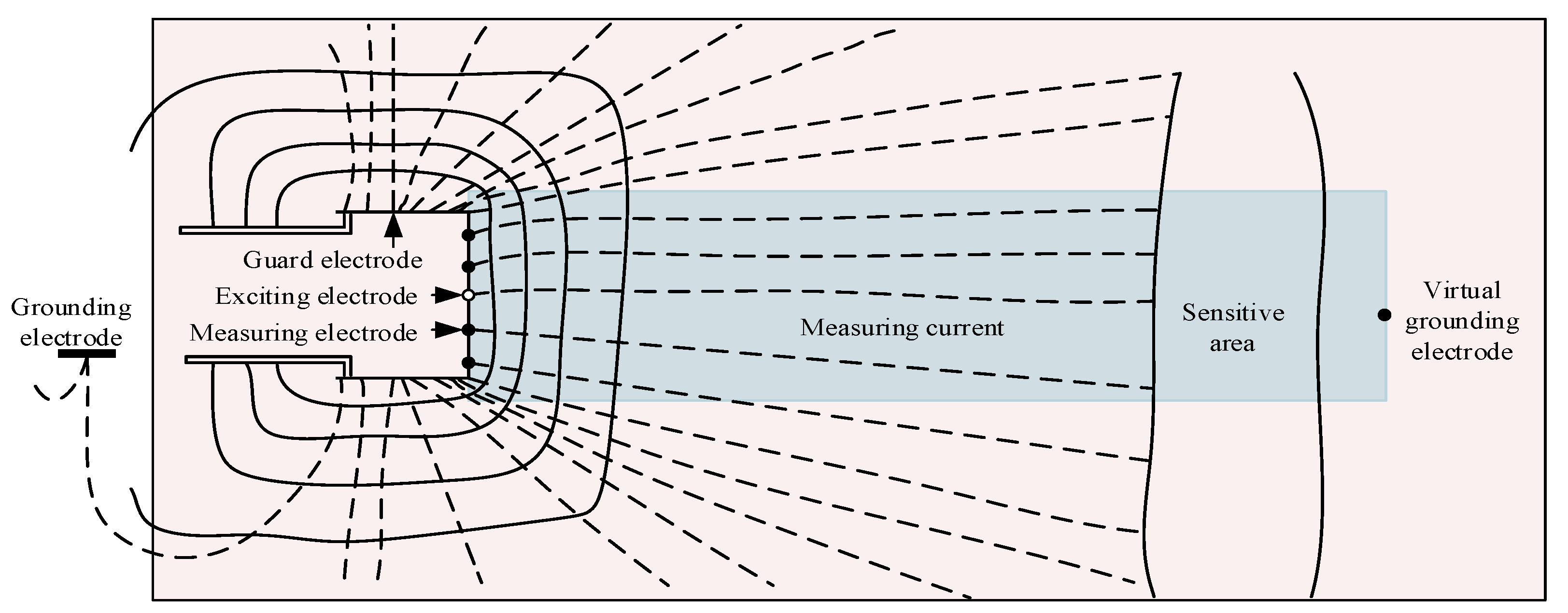
The electrical prospecting method is a geophysical detection method for ore prospecting and geological structure research through the difference in electrical properties of rocks and ores. The most commonly methods in electrical prospecting are direct current resistivity (DCR) method and induced polarization (IP) method [21]. However, the DCR method is easy to be interfered by the anomalous body near survey lines behind the tunnel face, which can easily lead to the reduction of prediction accuracy and even false alarm [22]. The bore-tunneling electrical ahead monitoring (BEAM) system is an IP method in focusing current frequency domain, which is developed by German company Geo Hydraulic Data. Its detection principle is to obtain the percentage frequency effect (PFE) value and apparent resistivity of rock mass pores by emitting the measuring current to the rock mass, and thereby to detect rock mass quality, voids, and water bodies in the rock mass according to these two parameters. The BEAM system is applied to tunnel construction under various complicated geological conditions, mainly including the Ginori tunnel in Italy, the Gotthard base tunnel in Switzerland and the Irlahul tunnel in Germany [23]. The BEAM system has high detection sensitivity, good stability, and can realize real-time on-line detection. However, as it only uses the continuous detection results of different mileages, but not the tomography, to qualitatively infer the geological conditions in front of the tunnel face, the BEAM system has great problems in positioning accuracy, detection distance, resolution and so on. Zhao et al., has utilized the tomography technique to invert the resistivity distribution caused by the stress change of the force sensitive material, which provided a solution to the imaging problem of the BEAM system [24].
The advanced horizontal drilling method is to carry out advanced horizontal drilling to determine the distribution of strata, the hardness of strata rocks, the integrity of rock masses and the position of faults and holes that may exist in front of the tunnel face by drilling speed testing, core taking rate statistics, core identification, and other means. As TBM often needs to be shut down and overhauled during the construction process, the multi-directional support hydraulic advanced geological drilling rig equipped on TBM is used for advanced drilling at the moment. However, due to its high cost, long time-consuming and small lateral detection range, this method has great application limitation in TBM tunnel advanced detection. Therefore, this method is commonly used in advanced detection in TBM tunnel construction together with other advanced geological prediction methods. Li has comprehensively analyzed and predicted the geological conditions in front of the tunnel face with transient electromagnetic method (TEM) and advanced horizontal drilling method [25].
Based on the above research background, a coal mine inclined shaft advanced detection method based on shield cutterhead moving array electrodes is proposed, which can realize real-time imaging during TBM construction in order to realize rapid excavation and optimize safety plans and supporting measures in advance. First, aiming at the problem that the BEAM system cannot image because of the low utilization rate of the spatial distribution information, a diversified excitation and measurement mode with the cutters on the cutterhead as the exciting electrode and measuring electrode is proposed, which provides a calculation condition for resistivity imaging of the geological condition in front of the driving face. Then, a virtual grounding electrode equivalent model is proposed to improve the speed of inversion imaging. Finally, in order to verify the effectiveness of this method, the influence of the virtual grounding electrode on the inversion results at different positions is studied through a physical model test and a numerical inversion test.

2. Theory

2.1. Detection Mechanism

When the exciting electrode supplies a stable current to the ground, the anomalous body will be polarized into a primary cell by an electrochemical reaction, which is caused by the current passing through the anomalous body. At this time, the primary cell will generate a secondary current to form an electric field in the space on the basis of the secondary current. The potential difference generated between the measuring electrodes is called a secondary potential difference, which will attenuate with time. The potential difference measured by the measuring electrode is the sum of the primary potential difference and the secondary potential difference, called the total field potential difference [26]. During the polarization process of the anomalous body, the speed will slow down until the anomalous body is finally saturated. After the power supply is disconnected, the anomalous body will continue to discharge due to the polarization effect of the anomalous body, even if there is no power supply current. As the discharge process continues, the voltage between the measuring electrodes will eventually decay and vanish. The above series of electrochemical reactions are called the IP effect. The rocks with different conductivity types correspond to different mechanisms of IP, thus different strata can be categorized into electronic conductors and ionic conductors according to their conductivity to current. Electronic conductors mainly refer to conductors or semiconductors such as graphite, metal deposits, and mineralized rocks, while ionic conductors refer to the rock strata besides the electronic conductors, of which rock-forming minerals are the solid electrolytes or the liquid surrounded by rock strata. The theory of IP of electronic conductors is generally believed that when an external electric field acts on rock mass, the electric charge inside the electronic conductor will be redistributed: The negative charge in the electronic conductor moves against the current flow direction and accumulates at the current inflow end to form a “cathode”; on the contrary, the remaining positive charges accumulate at the current outflow end to form an “anode”. This phenomenon of potential balance variation caused by the movement of the charge forms an IP of electronic conductors. Because the process of induced polarization of ionic conductors is very complicated, there is no unified explanation about its formation. Scholars agree that negative potential will appear on the surface of the ionic conductor in the rock mass to attract positive ions in the medium on the surface to form an electric double layer. Under the action of external electric field, current will carry away a large number of ions, which will lead to the accumulation of the negative ions and positive ions until the equilibrium state is reached.
The coal mine inclined shaft advanced detection method based on shield cutterhead moving array electrodes is essentially a focusing IP method, and its working principle is shown in Figure 1. Considering one of the measuring electrodes arranged on the cutterhead as the exciting electrode, when the exciting electrode sends out a detection signal, the electric field generated by the exciting electrode will propagate around the surrounding rock, which will cause an IP effect in the nearby medium. However, as the electric field propagates outward, the electric field is produced not only in the detection path, but also in every direction of the exciting electrode. In this way, the electric field will propagate in an unrelated direction, and tend to decay faster, which will affect the detection distance. In this case, around the exciting electrode should be arranged a ring-shaped guard electrode which has the same polarity of current of the exciting electrode. Due to the mutual repulsion of the same polarity current, the electric field formed by the guard electrode will generate a restraining current next to the exciting electrode to squeeze the current emitted by the exciting electrode, thus that the measuring current will focus into the sensitive area to be detected, thus reducing the attenuation of the excitation signal in the propagation process and increasing the detection distance. During detection, the voltage between the other measuring electrodes except the exciting electrode and the grounding electrode should be measured. After the measurement of each measuring electrode is finished, the cutterhead turns a certain angle and the above operation should be continued until the detection is finished when the measuring electrode system moves to a predetermined position. By analyzing and processing the voltage information obtained from the measuring electrodes, the existence and position of the anomalous body in front of the driving face are imaged according to a certain algorithm. If the traditional resistivity inversion imaging method is used, it is necessary to complete resistivity inversion with inversion algorithm after dividing the pink area in Figure 1 into finite elements. Due to the limited number of the cutters on the cutterhead, which are used as the measuring electrodes and the existence of the guard electrode, the number of the model units is excessive, which lead to the singularity of the solution matrix and thus the failure on solution. In this case, the forward “squeezing” of the current lines caused by the guard electrode can be approximately equivalent to placing a virtual grounding electrode behind the anomalous body to “stretch” the detection current backward, and the inversion target region can be simplified as the blue region in Figure 1. This equivalent simplification can improve the inversion imaging speed to meet the requirements of real-time detection.

2.2. System Composition and Layout

The coal mine inclined shaft advanced detection system based on shield cutterhead moving array electrodes is mainly composed of an array electrode unit, a data acquisition unit and an image reconstruction unit, as shown in Figure 2. The array electrode unit obtains the voltage distribution information in front of the tunnel face. The data acquisition unit collects the voltage information obtained by the array electrode unit and transmits it to the image reconstruction unit, which reconstructs the conductivity distribution image according to a certain algorithm.
The layout of the coal mine inclined shaft advanced detection system based on shield cutterhead moving array electrodes is completed according to the TBM construction environment, as shown in Figure 3. The array electrode unit mainly comprises the measuring electrode, guard electrode, and grounding electrode. In the direction of the diameter of the cutterhead, several cutters are selected as the measuring electrodes, and insulation treatment is required between each measuring electrode and cutterhead. In addition, the shield of TBM is used as the guard electrode, and an anchor rod is also required to be fixed on the side wall behind the TBM as the grounding electrode. Theoretically, when the distance between the grounding electrode and the measuring electrode is six times larger than the radius of the cross section of the guard electrode, the influence of infinity on the observation data can be ignored. The data acquisition unit and the image reconstruction unit are installed in the master control room of TBM and are connected with the guidance system and the programmable logic controller (PLC) to receive the position and tunneling status signals of TBM thus as to ensure the automatic data acquisition and real-time display.

2.3. Solution of the Focusing Electric Field

There are two methods to solve the focusing electric field, namely the total potential method and the abnormal potential method. When the total potential method is used to solve the problem, the error in the total potential value near the power supply point is quite considerable, because there is a power supply term in function of the total potential, which is singular at the power supply point. When the abnormal potential method is used to solve the problem, because there is no power supply term in function of the abnormal potential, the calculation accuracy near the power supply point is effectively improved. Therefore, the abnormal potential method is adopted to solve the focusing electric field.
Assuming that there is a point source A with current intensity I in a homogeneous medium with conductivity σ , and the current density vector flowing from the point power supply is j . The expression of the relationship between the potential u and the conductivity σ can be presented as follows:
j = σ u
At any closed surface Γ in space, Ω is the area surrounded by Γ . According to the Gauss flux law, the total amount of current flowing through the closed surface Γ is as follows:
Γ j · d Γ = Ω · j d Ω = { 0 A Ω I A Γ
δ ( A ) denotes the δ function centered on A in the whole space. According to the global integral properties of the δ function, there is:
Ω δ ( A ) = { 0 A Ω 1 A Γ
By comparing the above Equations (1), (2), and (3), the following relational expressions are obtained as follows:
· ( σ · u ) = I δ ( A )
In the focusing electric field, the total potential ν is the sum of the normal potential value u 0 and the abnormal potential value u , namely.
ν = u 0 + u
If there is an anomalous body with conductivity σ in the uniform earth with conductivity σ 0 , The abnormal conductivity σ can be expressed as follows:
σ = σ σ 0
The total potential ν satisfies the Equation (4), and according to the above assumption, the basic differential equation of the total potential ν can be decomposed into:
· ( σ · ν ) = · ( σ · u + σ · u 0 + σ 0 · u 0 ) = I δ ( A )
Definition: If · ( σ 0 · u 0 ) = I δ ( A ) , then the basic differential equation of the abnormal potential u can be denoted as follows:
· ( σ · u ) = · ( σ · u 0 )
The boundary conditions of the abnormal potentials u are as follows:
{ u n = 0 Γ s u n + cos ( r , n ) r u = 0 Γ
where, r is the distance from the measuring point to power supply point A, n is the outer normal direction of the boundary, Γ s is the ground boundary, and Γ is the boundary of infinity.
The equivalent variation problems are:
F ( u ) = Ω [ 1 2 σ ( u ) 2 + σ u 0 · u ] d Ω + Γ [ 1 2 σ cos ( r , n ) r u 2 + σ cos ( r , n ) r u 0 u ] d Γ
F ( u ) = 0
The following linear algebraic equations can be obtained from Equations (10) and (11) by dividing the region by finite element method and integrating it in general:
K u = K u 0
where, K = σ ( K 1 + K 2 ) , K = σ ( K 1 + K 2 ) , K 1 is the coefficient matrix of the first term volume integral at the right end in Equation (10), K 2 is the coefficient matrix of the second term boundary integral at the right end in Equation (10), u is the vector containing abnormal potential values of all nodes of the model, and u 0 is the vector containing normal potential values of all nodes of the model.
By solving the large sparse linear equations formed by the integration of the element nodes of Equation (12), the abnormal potentials u of each node of the unit can be obtained.

2.4. Inversion Imaging Analysis

Inversion imaging, which is an important link in the advanced detection system, essentially is to establish a nonlinear mapping model from the sampled voltage value to the pixel gray level of the image, which aims at rebuilding the algorithm to realize the approximation of this nonlinear mapping with the corresponding image, thus that the conductivity distribution in front of the tunnel face can be directly reflected from the measuring voltage value.
In the ideal noise-free environment, the forward problem of the advanced detection can be presented as follows:
V = F ( ρ )
where, V is the voltage between the measuring electrode and the grounding electrode, F is the forward operator, and ρ is the resistivity of the surrounding rock.
After the Equation (13) is linearized, we can get the relationship between the voltage change Δ V and the resistivity change Δ ρ by the Taylor expansion method.
Δ V = δ F δ ρ ( Δ ρ ) + O ( ( Δ ρ ) 2 )
If Δ ρ is small enough, the higher order term in Equation (14) can be ignored, then Equation (14) can be simplified to:
Δ V = S ( Δ ρ )
where S is called the Jacobian matrix. Assuming that the geo-electric model is divided into m elements, and there are n independent measuring data. The following equation can be obtained by discretizing and normalizing Equation (15):
U = S · G
where U is the measuring voltage vector after n dimension normalization, S is the Jacobian matrix after n × m dimension being normalized, and G is the resistivity distribution vector after m × 1 dimension being normalized.
Inversion imaging is the process of solving the inverse problem for the forward problem Equation (13) of the advanced detection system.
ρ = F 1 ( V )
The approximate linear solution equation of the inverse problem of the advanced detection can be obtained from Equation (16).
G = S 1 ( U )

3. Materials and Methods

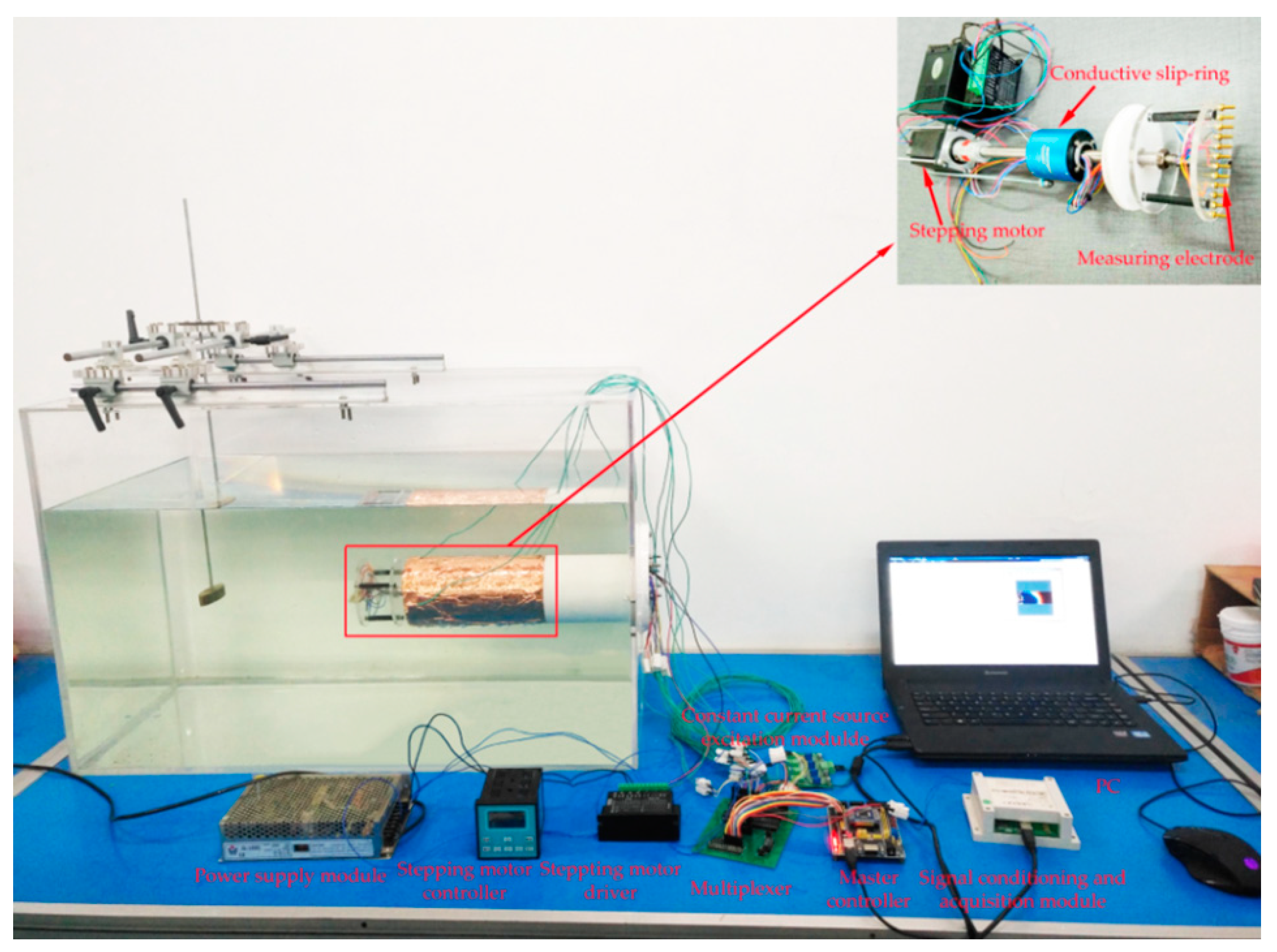
The physical model test device is shown in Figure 4. The outer shell of the physical model is made of the acrylic plate with a length of 0.8 m, a width of 0.4 m, a height of 0.5 m, and a thickness of 0.008 m. An elliptical cylindrical brass with a major axis of 0.08 m, a minor axis of 0.02 m, a thickness of 0.02 m, and a resistivity of 0.05 Ω · m was selected as the low resistivity anomalous body. A working platform, which can move along the X-Y-Z direction is installed on the acrylic box and can be used for clamping and moving various anomalous bodies. In order to make the electrode fully contact with the medium when the cutterhead rotates, water with a resistivity value of 20 Ω · m is filled into the acrylic box as simulated surrounding rock, and the water level is 0.4 m. A polyvinyl chloride (PVC) pipe with an outer diameter of 0.1 m and an inner diameter of 0.09 m was fixed on the acrylic box to simulate the shield machine body. A layer of copper foil was pasted on the front end of the PVC pipe to simulate the shield with 4 copper electrodes being pasted around the simulated shield as the guard electrodes. The simulated cutterhead made of acrylic circular plate, with a thickness of 0.005 m and a diameter of 0.1 m, installed on the front end of the PVC pipe. We installed 12 copper bolts with a diameter of 0.003 m in the diameter direction of the simulated cutterhead as the measuring electrodes, and the distance between the 2 adjacent measuring electrodes was 0.008 m. The simulated cutterhead was fixed on a stainless-steel hollow shaft with a waterproof sealing bearing, a conductive slip-ring, a coupling and a stepping motor fixed on, wherein the conductive slip-ring is to prevent the wires connecting the measuring electrodes from winding together when the simulated cutterhead rotates. The stepping motor was connected with the driver and the controller to drive and control the simulated cutterhead. The distance from the simulated cutterhead to the left end of the acrylic box was 0.4 m, and the distance to the lower end of the acrylic box was 0.2 m. In addition, a copper bolt was also required to be installed on the acrylic box as the grounding electrode.
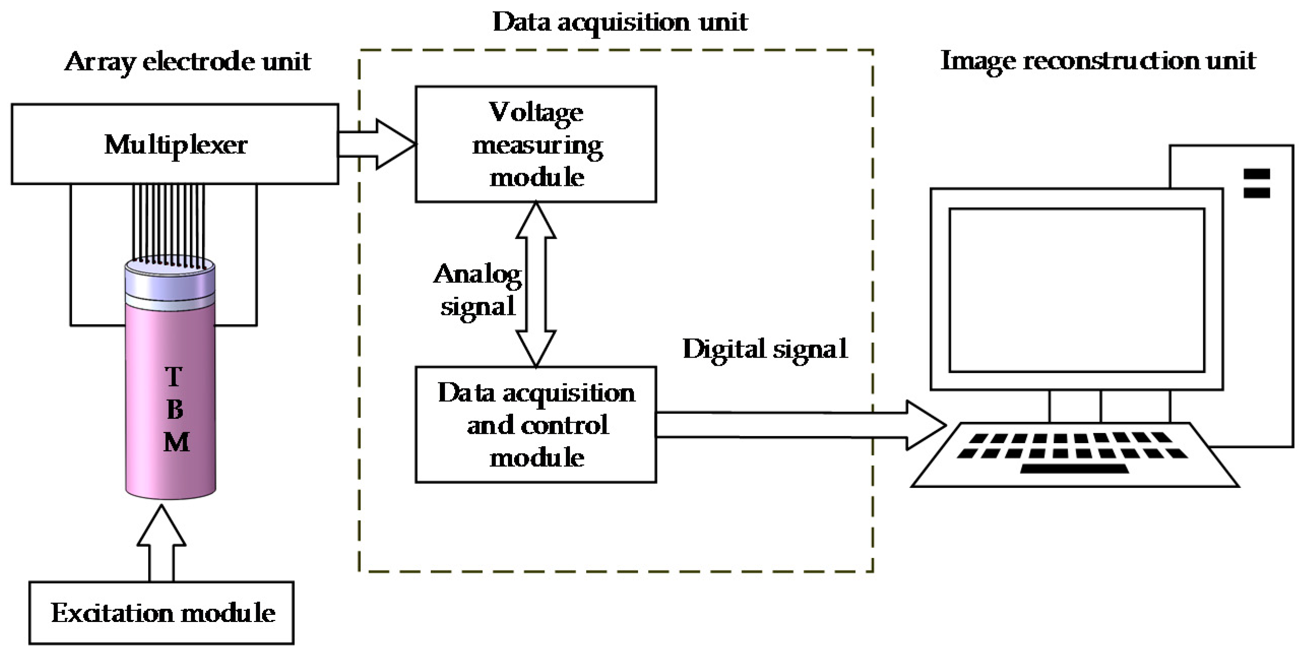
The system of the physical model test mainly included a power supply module, a master controller, a multiplexer, a constant current source excitation module, a signal conditioning, and an acquisition module and an imaging module. The power supply module used a switch mode power supply to provide different voltages. The master controller used MSP430F149 as the control chip, which has ultra-low power consumption. The multiplexer used a high-precision 16-channel multiplexer analog switch CD4067 to meet the switching and gating of 12 electrodes. The constant current source excitation module used a high-precision amplifier OP77, which can obtain current signals between 50 uA and 10 mA. The signal conditioning and acquisition module was divided into two parts: Signal conditioning and data acquisition. The signal conditioning part consisted of a first-stage amplifier circuit composed of an instrument amplifier with high input impedance and high common-mode rejection ratio and a second-stage program-controlled amplifier composed of a low input bias voltage, a broadband high-speed operational amplifier, and a numerical control potentiometer. The data acquisition part consisted of a voltage follower and a 24-bit high-precision digital-to-analog conversion chip ADS1256. The imaging module used a personal computer (PC) to display the imaging results. The working process of the system was as follows: When the system was powered on and received the command to start acquisition, the master controller controlled the constant current source excitation module to generate current excitation with specific parameters. Under the control of the master controller, the exciting current was sequentially released to each electrode through the multiplexer, and at the same time, the voltage signals at each measuring electrode were sent to the signal conditioning and acquisition module. After the processing and acquisition of the voltage signal were completed, the master controller transmitted the data to the PC for imaging in real time.

4. Results and Discussion

The anomalous body is located at the central axis of the cutterhead, and the distance between its geometric center and the cutterhead is L. The direct current supplied to the exciting electrode is I 0 , and the direct current supplied to the guard electrode is I 1 . 
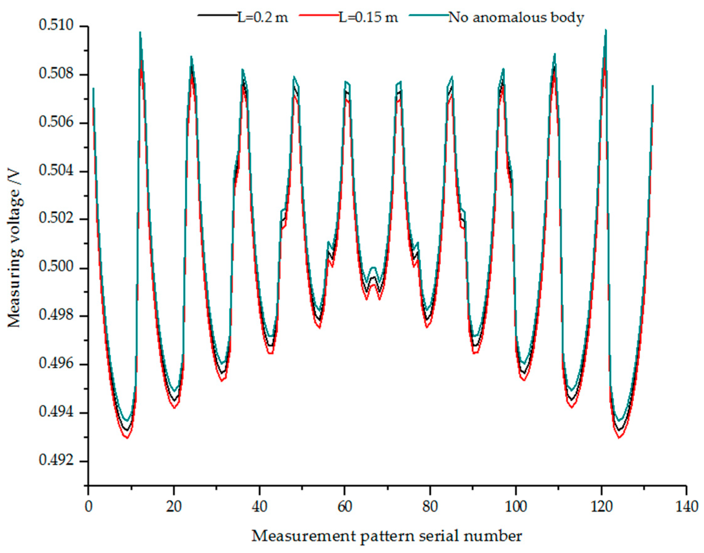
Figure 5 represents the measuring voltage at I 0 = I 1 = 1 mA when no anomalous body exists and the measuring voltage when L = 0.15 m and 0.2 m, respectively. 
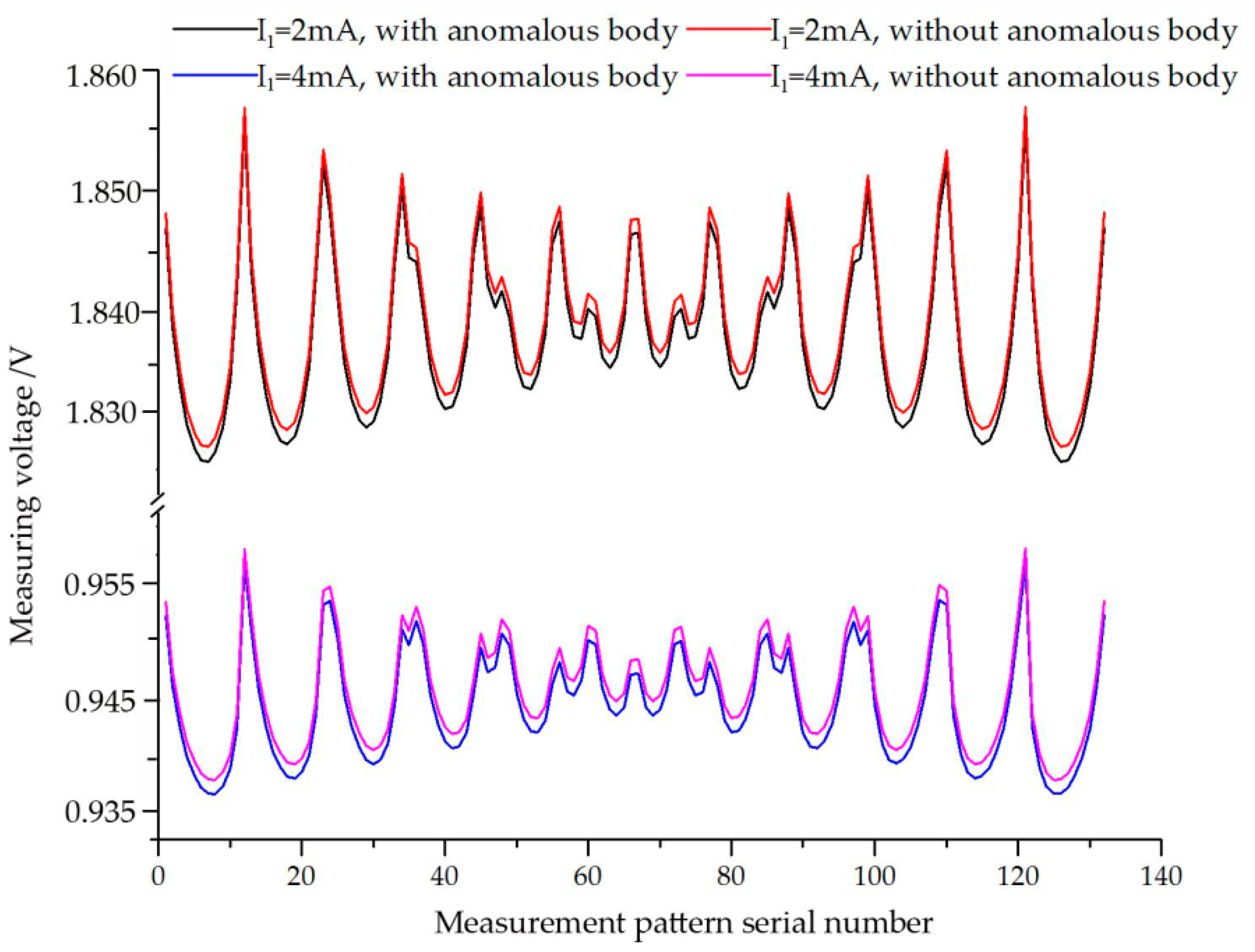
Figure 6 represents the measuring voltage at I 0 = 1 mA, I 1 = 2 mA and 4mA when no anomalous body exists and the measuring voltage when L = 0.15 m, I 0 = 1 mA, and I 1 = 2 mA and 4 mA, respectively.
Since 12 measuring electrodes are arranged on the cutterhead, according to the measuring method described in Section 2.1, 11 voltage data can be obtained by supplying power to one measuring electrode at a time, and 132 voltage data can be obtained by supplying power to these 12 measuring electrodes in turn. As can be seen from Figure 5 and Figure 6, when the same amount of current is supplied to the exciting electrode and the guard electrode, the farther away the low resistivity anomalous body is from the cutterhead, the greater the voltage measured by each measuring electrode. When the distance of the anomalous body and the exciting current are constant, the measuring voltage is approximately proportional to the guard current. Since the 12 measuring electrodes are uniformly distributed around the center of the circle on the cutterhead, the voltages obtained from the 1st and 12th, 2nd and 11th, ..., 6th and 7th measurements are approximately equal.
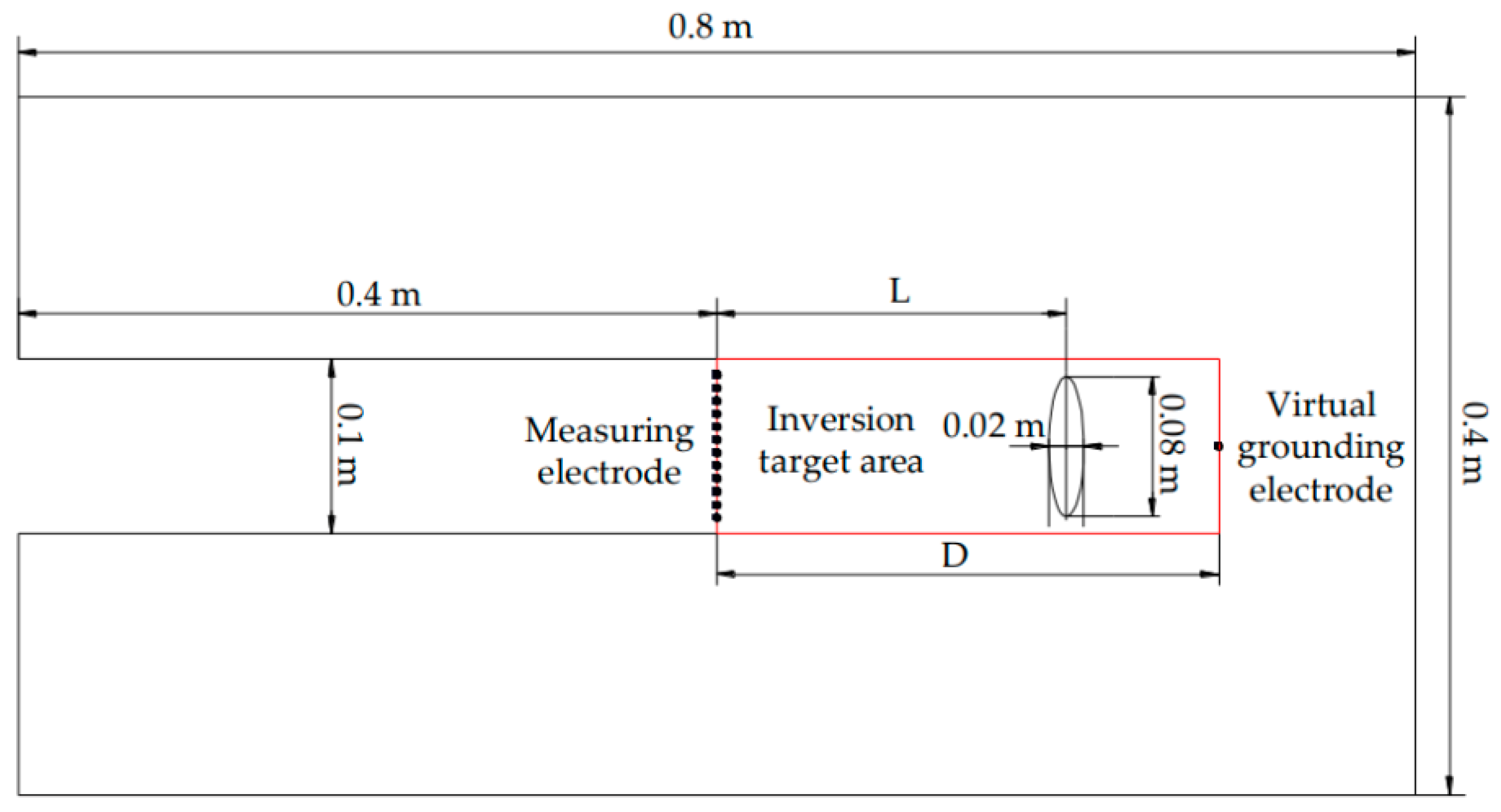
After obtaining the voltage data, inversion imaging can be performed. In actual inversion, as the resistivity change of the elements far away from the anomalous body is slight, it does not need inversion calculation in the model units with very small resistivity changes. Consequently, the number of elements in the model will be greatly reduced, which is helpful to improve the inversion speed. According to the geometric dimensions and material properties of the physical model, a virtual ground electrode model is established as shown in Figure 7. The area in the red rectangular wireframe in Figure 7 is considered as the inversion target area. The width of the inversion target area is the diameter of the cutterhead of TBM, and the length is the distance between the virtual grounding electrode and the cutterhead.
Assuming that the distance from the virtual grounding electrode to the cutterhead is D. 
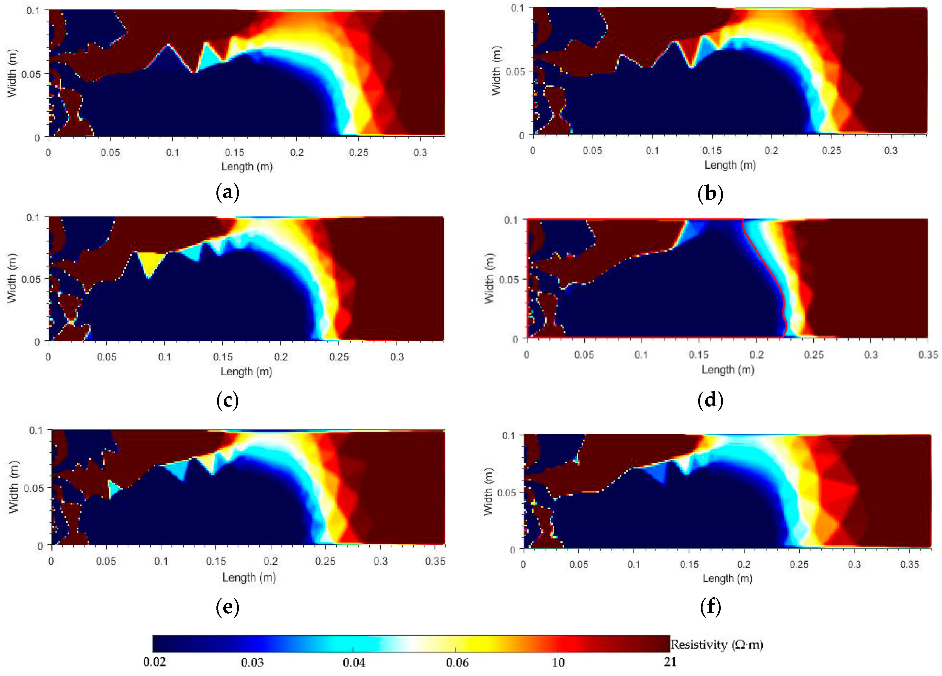
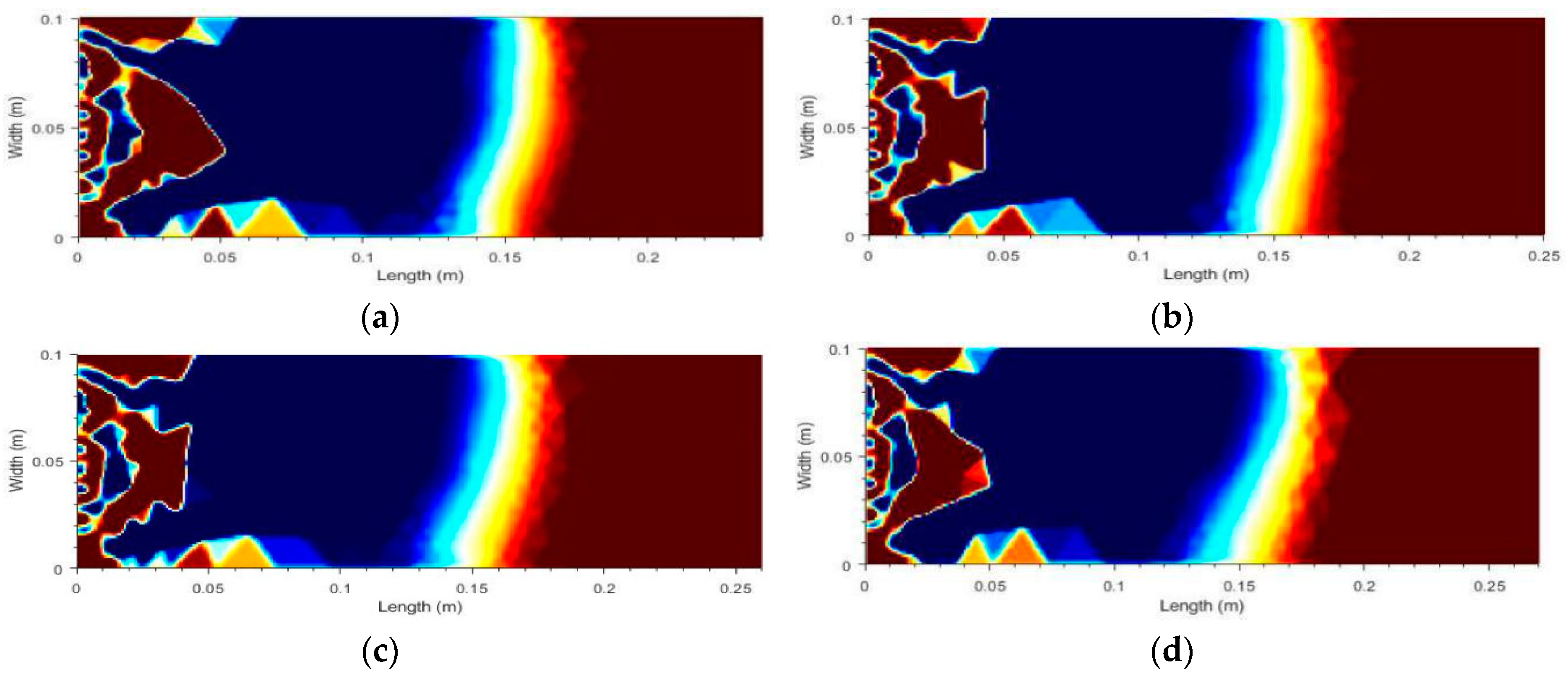
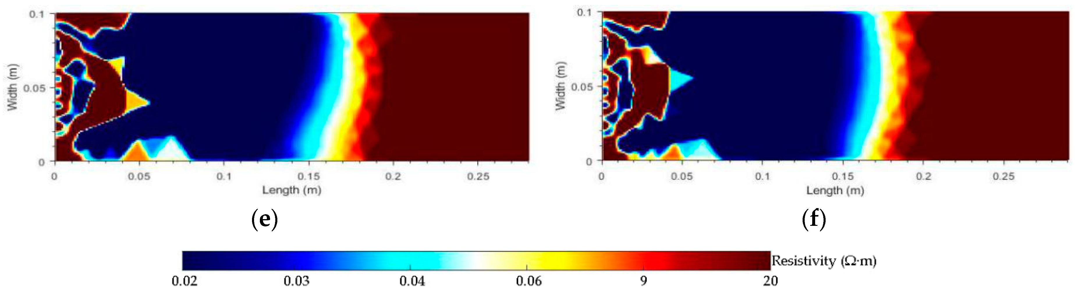
Figure 8 is the inversion results of the anomalous body at different distances when L = 0.2 m and I 0 = I 1 = 1 mA. 
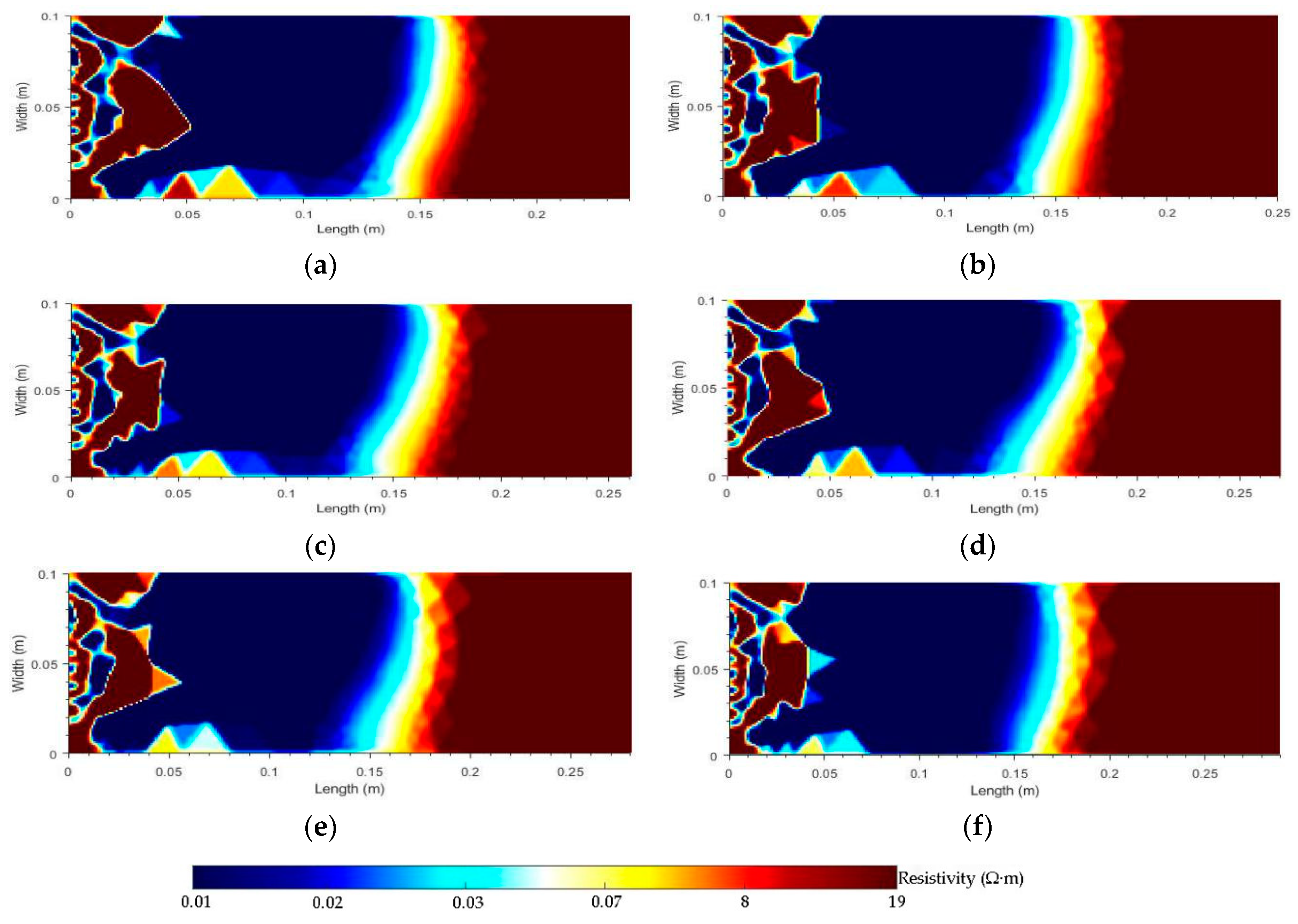
Figure 9 is the inversion results of the anomalous body at different distances when L = 0.15 m and I 0 = I 1 = 1 mA. Figure 10 is the inversion results of the anomalous body at different distances when L = 0.15 m, I 0 = 1 mA and I 1 = 2 mA. Figure 11 is the inversion results of the anomalous body at different distances when L = 0.15 m, I 0 = 1 mA and I 1 = 4 mA. As can be seen from Figure 8, Figure 9, Figure 10, and Figure 11, when L = 0.2 m, I 0 = I 1 = 1 mA and D = 0.35 m, the position of the anomalous body in the numerical inversion test is between 0.21 m and 0.23 m, and the relative error of the position of anomalous body in the physical model test is between 1% and 3%; when L = 0.15 m, I 0 = I 1 = 1 mA and D = 0.26 m, the position of the anomalous body in the numerical inversion test is between 0.145 m and 0.16 m, and the relative error of the position of anomalous body in the physical model test is between 0.5% and 1%; when L = 0.15 m, I 0 = 1 mA, I 1 = 2 mA and D = 0.26 m, the position of the anomalous body in the numerical inversion test is between 0.14 m and 0.17 m, and the relative error of the position of anomalous body in the physical model test is between 1% and 2%; when L = 0.15 m, I 0 = 1 mA, I 1 = 4 mA and D = 0.27 m, the position of the anomalous body in the numerical inversion test is between 0.148 m and 0.16 m, and the relative error of the position of anomalous body in the physical model test is between 0.2% and 1%. The position error of the anomalous body in the numerical inversion test and the physical model test is mainly caused by the interference of the electrochemical phenomenon in the water tank to the measuring voltage. The resistivity of the area between the anomalous body and the tunnel face is uneven, as shown in the red wireframe area of Figure 8d. This is because when the inversion imaging is performed using the virtual grounding electrode equivalent model to replace the original guard electrode model, the measuring voltage in the presence of the guard electrode is used as the priori information of the inversion, which makes the apparent resistivity of the area between the anomalous body and the cutterhead smaller. With the increase of the guard current, the apparent resistivity of the area between the anomalous body and the cutterhead changes more regularly, and the position of the inverted anomalous body are more accurate.

5. Conclusions

In this paper, a coal mine inclined shaft advanced detection method based on shield cutterhead moving array electrodes is proposed. The superiority of this method is that the cutters on the cutterhead of the TBM and the components assembled safely are used as the measuring electrodes, which are automatically electrically connected to the stratum through the TBM entity, and the data are automatically collected along with the rotation of the cutterhead, by which the geological detection results are displayed in real time. This method is verified by a physical model test and a numerical inversion test, and the following conclusions are obtained: (1) A virtual grounding electrode equivalent model is proposed to replace the original guard electrode model and the influence of the virtual grounding electrode on the inversion results at different positions is studied. The inversion results show that this method can better reflect the position of the anomalous body in front of the driving face. (2) Since the voltage measurement method and inversion algorithm are the same in other positions when the cutterhead rotates, this paper only accomplishes the measurement on the voltages of the measuring electrode being located in the horizontal position and the two-dimensional resistivity inversion imaging. In the next stage, it is necessary to measure the voltages of the cutterhead in different angles to obtain more effective information for three-dimensional resistivity inversion imaging. (3) The resistivity inversion imaging in TBM advanced detection is a typical multi-field coupling problem combining electro-thermal-hydro-chemo-mechanical fields (ETHCM). The further research on the detection mechanism, inversion interpretation, and increase of effective observation data are urgently needed, as well as the site verification.

Author Contributions

S.Z. conceived and designed the research. M.W. and Z.L. performed the experiments. C.Z. and W.G. analyzed the data. S.Z. and M.W. wrote the paper.

Acknowledgments

This work was supported by the Natural Science Foundation of Shaanxi Province (Program No. 2017JM5029), Xi’an Science and Technology Project (Project NO. CXY2017079CG/RC042) and National Key R&D Program of China (Program No. 2017YFC0804310).

Conflicts of Interest

The authors declare no conflict of interest.

References

  1. Belle, B.; Foulstone, A. Explosion Prevention in Coal Mine TBM Drifts-An Operational Safety Knowledge Share. Procedia Earth Planet. Sci. 2015, 11, 15–28. [Google Scholar] [CrossRef]
  2. Huang, X.; Liu, Q.; Shi, K.; Pan, Y.; Liu, J. Application and Prospect of Hard Rock TBM for Deep Roadway Construction in Coal Mines. Tunn. Undergr. Sp. Technol. 2018, 73, 105–126. [Google Scholar] [CrossRef]
  3. Farrokh, E.; Rostami, J. Effect of Adverse Geological Condition on TBM Operation in Ghomroud Tunnel Conveyance Project. Tunn. Undergr. Sp. Technol. 2009, 24, 436–446. [Google Scholar] [CrossRef]
  4. Davydycheva, S.; Rykhlinski, N.; Legeido, P. Electrical-Prospecting Method for Hydrocarbon Search Using The Induced-Polarization Effect. Geophysics 2006, 71, 179–189. [Google Scholar] [CrossRef]
  5. Chen, G.; Wu, Z.; Wang, F. Study on the application of a comprehensive technique for geological prediction in tunneling. Environ. Earth Sci. 2011, 62, 1667–1671. [Google Scholar] [CrossRef]
  6. Khave, G.J. TBM Tunnelling in Hydrogen Sulfide Gas Bearing Ground and its Solutions. Geotech. Geol. Eng. 2013, 31, 1621–1638. [Google Scholar] [CrossRef]
  7. Alimoradi, A.; Moradzadeh, A.; Naderi, R. Prediction of geological hazardous zones in front of a tunnel face using TSP-203 and artificial neural networks. Tunn. Undergr. Sp. Technol. 2008, 23, 711–717. [Google Scholar] [CrossRef]
  8. Lin, C.; Li, S. Tunnel seismic prediction (TSP) and its application in tunnel engineering. Appl. Mech. Mater. 2014, 501–504, 1779–1782. [Google Scholar] [CrossRef]
  9. Liu, B.; Chen, L.; Li, S.; Xu, X.; Liu, L.; Song, J.; Li, M. A new 3D observation system designed for a seismic ahead prospecting method in tunneling. Bull. Eng. Geol. Environ. Eng. 2018, 77, 1547–1565. [Google Scholar] [CrossRef]
  10. Petronio, L.; Poletto, F. Seismic-while-Drilling by Using Tunnel Boring Machine Noise. Geophysicists 2002, 67, 1798–1809. [Google Scholar] [CrossRef]
  11. Petronio, L.; Poletto, F.; Schleifer, A. Interface Prediction Ahead of The Excavation Front by The Tunnel-Seismic-while-Drilling (TSWD) Method. Geophysicists 2007, 72, 39–44. [Google Scholar] [CrossRef]
  12. Poletto, F.; Petronio, L. Seismic Interferometry with a TBM Source of Transmitted and Reflected Waves. Geophysicists 2006, 71, 185–193. [Google Scholar] [CrossRef]
  13. Ewald, B.; Werner, C.; Stefan, M. Exploration Ahead of a Tunnel Face by TSWD-Tunnel Seismic while Drilling. Geomech. Tunn. 2010, 1, 460–465. [Google Scholar]
  14. Kneib, G.; Kassel, A.; Lorenz, K. Automatic Seismic Prediction Ahead of The Tunnel Boring Machine. First Break 2000, 18, 295–302. [Google Scholar] [CrossRef]
  15. Mooney, M.A.; Walter, B.; Frenzel, C. Real-time Tunnel Boring Machine Monitoring: A state-of-The-Art Review. In Proceedings of the North American Tunneling; Society for Mining, Metallurgy, and Exploration: Littleton, CO, USA, 2012; pp. 73–81. [Google Scholar]
  16. Richard, O.; Edward, B.; Helfried, B. The Application of TRT-true Reflection Tomography-at The Unterwald Tunnel. Geophysics 2002, 67, 51–56. [Google Scholar]
  17. Yamamoto, T.; Shirasagi, S.; Yokota, Y. Imaging Geological Conditions Ahead of a Tunnel Face Using Three-dimensional Seismic Reflector Tracing System. Int. J. JCRM 2014, 6, 23–31. [Google Scholar]
  18. Zhao, S.; Liang, L.; Xu, G.; Wang, J.; Zhang, W. Quantitative Diagnosis of a Spall-like Fault of a Rolling Element Bearing by Empirical Mode Decomposition and The Approximate Entropy Method. Mech. Syst. Signal Process. 2013, 40, 154–177. [Google Scholar] [CrossRef]
  19. Zhao, S.; Wang, W.; Guao, W.; Zhang, C. A Human Body Pressure Distribution Imaging System Based on Wavelet Analysis and Resistance Tomography. Sensors 2017, 17, 2634–2642. [Google Scholar] [CrossRef]
  20. Inazaki, T.; Isahai, H.; Kawamura, S. Stepwise Application of Horizontal Seismic Profiling for Tunnel Prediction Ahead of The Face. Lead. Edge 1999, 18, 1429–1431. [Google Scholar] [CrossRef]
  21. Schaeffer, K.P. An Experimental and Computational Investigation of Electrical Resistivity Imaging for Prediction Ahead of Tunnel Boring Machines. Ph.D. Thesis, Colorado School of Mines, Golden, CO, USA, 2016. [Google Scholar]
  22. Li, S.; Liu, B.; Nie, L.; Liu, Z.; Tian, M.; Wang, S.; Su, M.; Guo, Q. Detecting and Monitoring of Water Inrush in Tunnels and Coal Mines Using Direct Current Resistivity Method: A Review. J. Rock Mech. Geotech. Eng. 2015, 7, 469–478. [Google Scholar] [CrossRef]
  23. Kaus, A.; Boening, W. BEAM-geoelectrical Ahead Monitoring for TBM-drives. Geomechanik Und Tunnelbau 2008, 1, 442–449. [Google Scholar] [CrossRef]
  24. Zhao, S.; Liu, M.; Guao, W.; Zhang, C. Three-dimensional Distribution of Sensitive Field and Stress Field Inversion of Force Sensitive Materials under Constant Current Excitation. Sensors 2018, 18, 722–741. [Google Scholar] [CrossRef] [PubMed]
  25. Li, J. Comprehensive Application of Transient Electromagnetism Method and Advanced Horizontal Drilling Method in Tunnel Construction. Value Eng. 2017, 36, 118–120. [Google Scholar]
  26. Zhang, F. Spectrum Parameters of Cole-cole Model Inversion Based on IP Data. Chin. J. Eng. Geophys. 2011, 8, 525–529. [Google Scholar]
Figure 1. The working principle of coal mine inclined shaft advanced detection method based on shield cutterhead moving array electrodes.
Energies 12 01671 g001
Figure 2. The composition of coal mine inclined shaft advanced detection system based on shield cutterhead moving array electrodes.
Energies 12 01671 g002
Figure 3. The layout of the coal mine inclined shaft advanced detection system based on the shield cutterhead moving array electrodes.
Energies 12 01671 g003
Figure 4. The diagram of the physical model test device.
Energies 12 01671 g004
Figure 5. Measuring voltage of anomalous body at different distances and without anomalous body.
Energies 12 01671 g005
Figure 6. Measuring voltage at different guard currents when there is an anomalous body and no anomalous body.
Energies 12 01671 g006
Figure 7. Schematic diagram of virtual grounding electrode model.
Energies 12 01671 g007
Figure 8. Inversion results of virtual grounding electrode at different distances when L = 0.2 m and I 0 = I 1 = 1 mA. (a) Is the inversion result when D = 0.32 m; (b) is the inversion result when D = 0.33 m; (c) is the inversion result when D = 0.34 m; (d) is the inversion result when D = 0.35 m; (e) is the inversion result when D = 0.36 m; (f) is the inversion result when D = 0.37 m.
Energies 12 01671 g008
Figure 9. Inversion results of virtual grounding electrode at different distances when L = 0.15 m and I 0 = I 1 = 1 mA. (a) Is the inversion result when D = 0.24 m; (b) is the inversion result when D = 0.25 m; (c) is the inversion result when D = 0.26 m; (d) is the inversion result when D = 0.27 m; (e) is the inversion result when D = 0.28 m; (f) is the inversion result when D = 0.29 m.
Energies 12 01671 g009
Figure 10. Inversion results of virtual grounding electrode at different distances when L = 0.15 m, I 0 = 1 mA and I 1 = 2 mA. (a) Is the inversion result when D = 0.25 m; (b) is the inversion result when D = 0.26 m; (c) is the inversion result when D = 0.27 m; (d) is the inversion result when D = 0.28 m; (e) is the inversion result when D = 0.29 m; (f) is the inversion result when D = 0.30 m.
Energies 12 01671 g010
Figure 11. Inversion results of virtual grounding electrode at different distances when L = 0.15 m, I 0 = 1 mA and I 1 = 4 mA. (a) Is the inversion result when D = 0.24 m; (b) is the inversion result when D = 0.25 m; (c) is the inversion result when D = 0.26 m; (d) is the inversion result when D = 0.27 m; (e) is the inversion result when D 0.28 m; (f) is the inversion result when D = 0.29 m.
Energies 12 01671 g011aEnergies 12 01671 g011b

