Novel Segmented Roadside Plugging-Filling Mining Method and Overlying Rock Mechanical Mechanism Analyses


Abstract
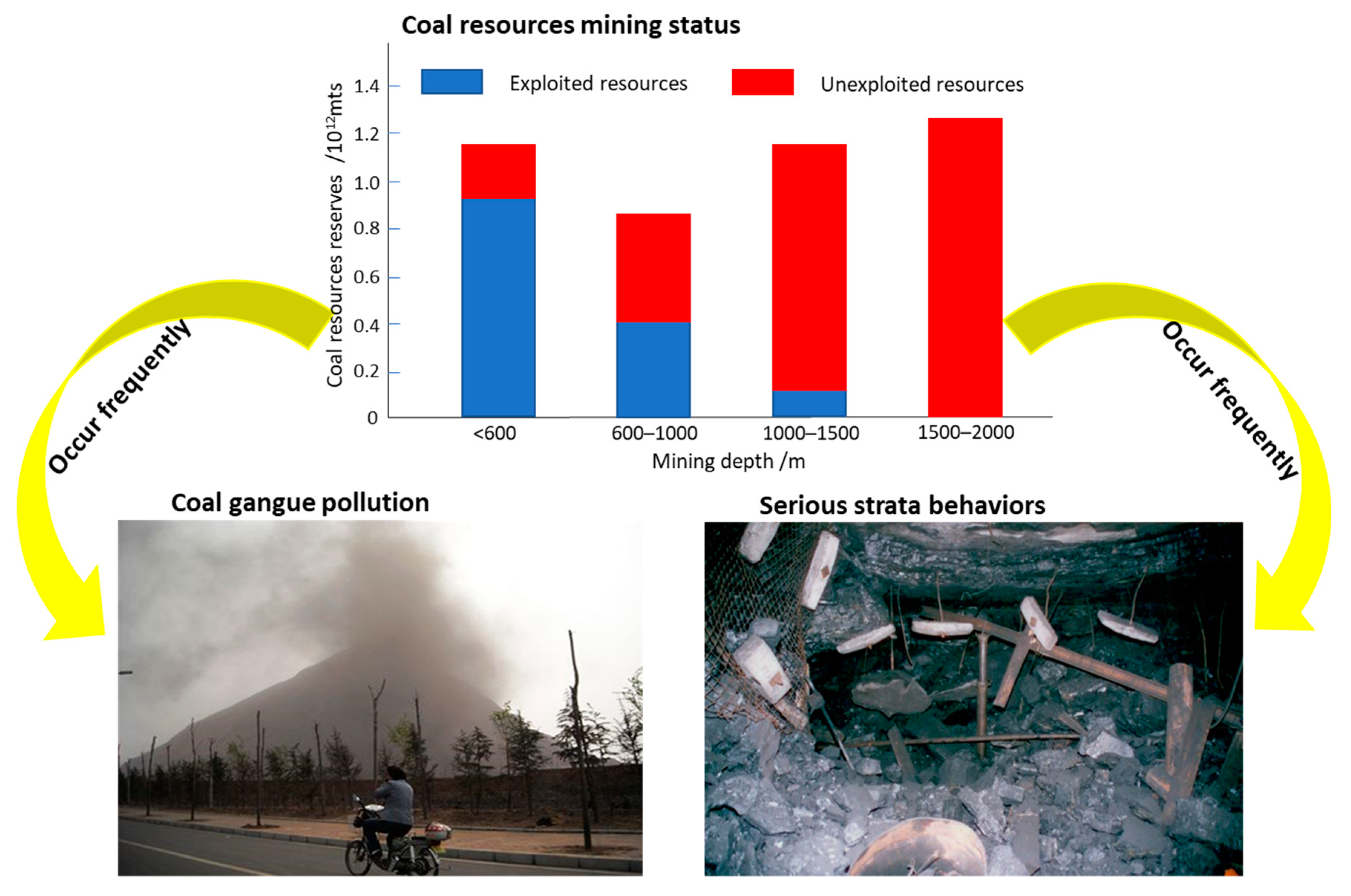
:1. Introduction
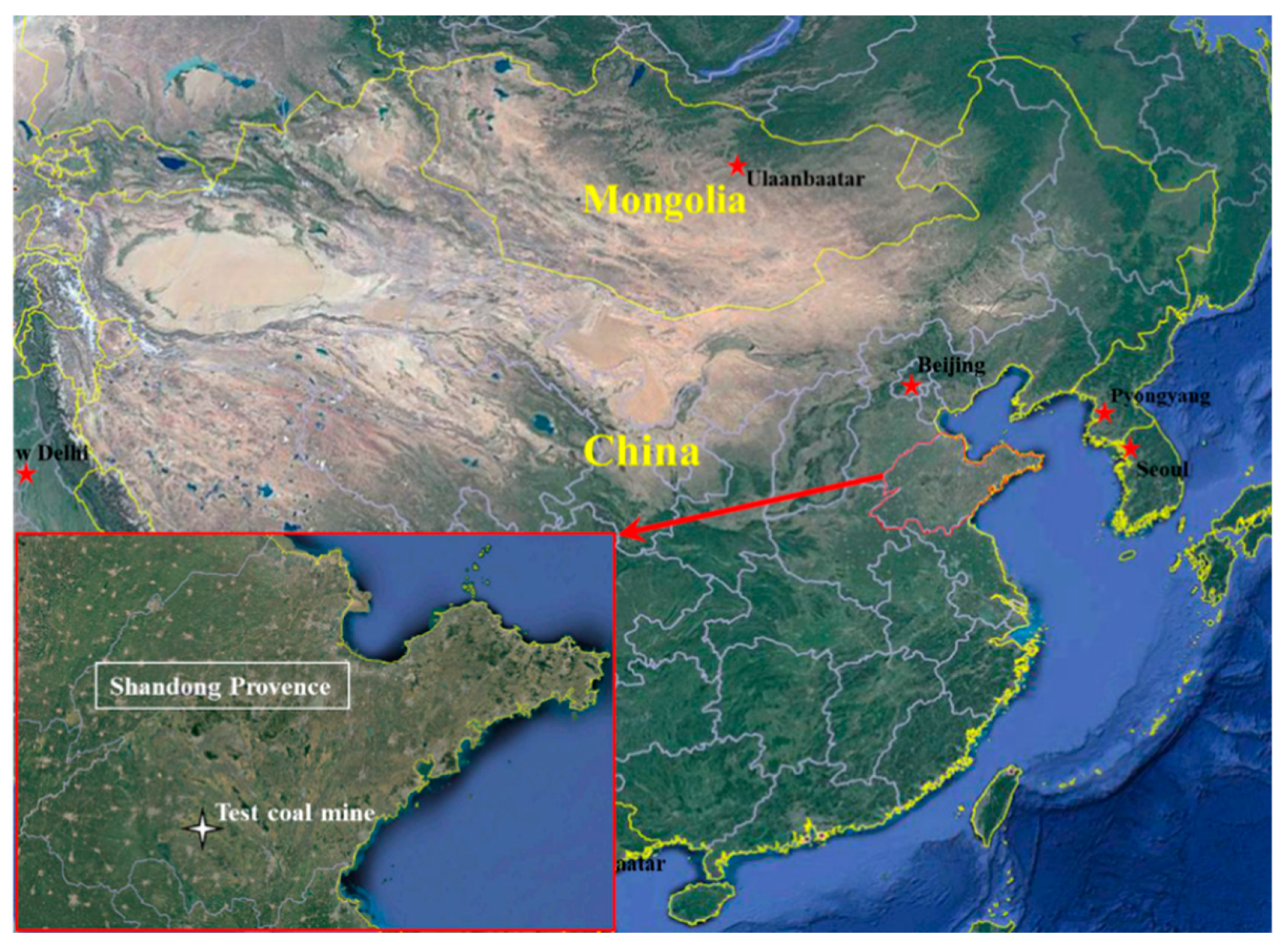
2. Mining and Geological Conditions
3. Innovative Method SRPF for GER Mining
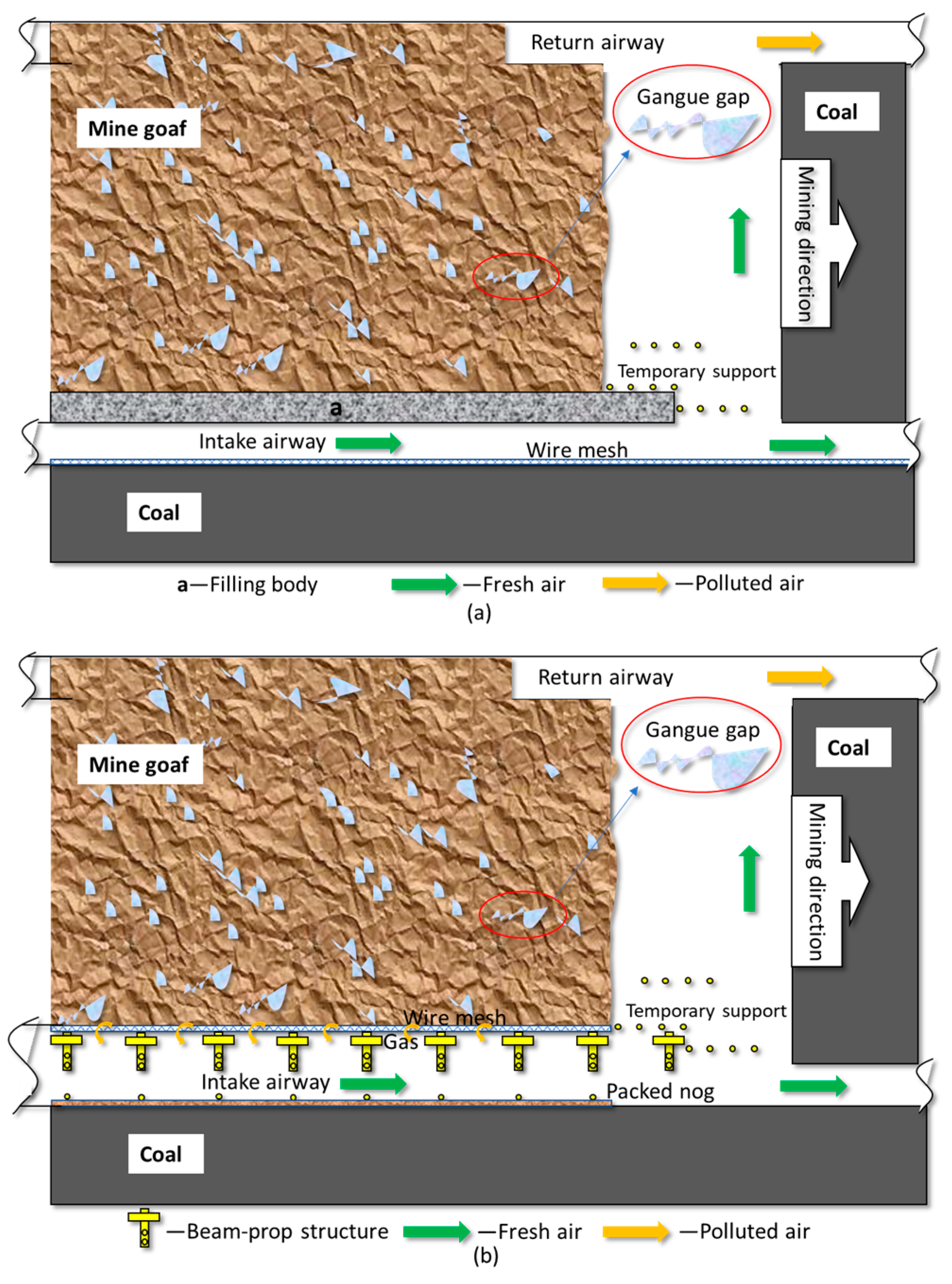
3.1. Conventional Forms for GER
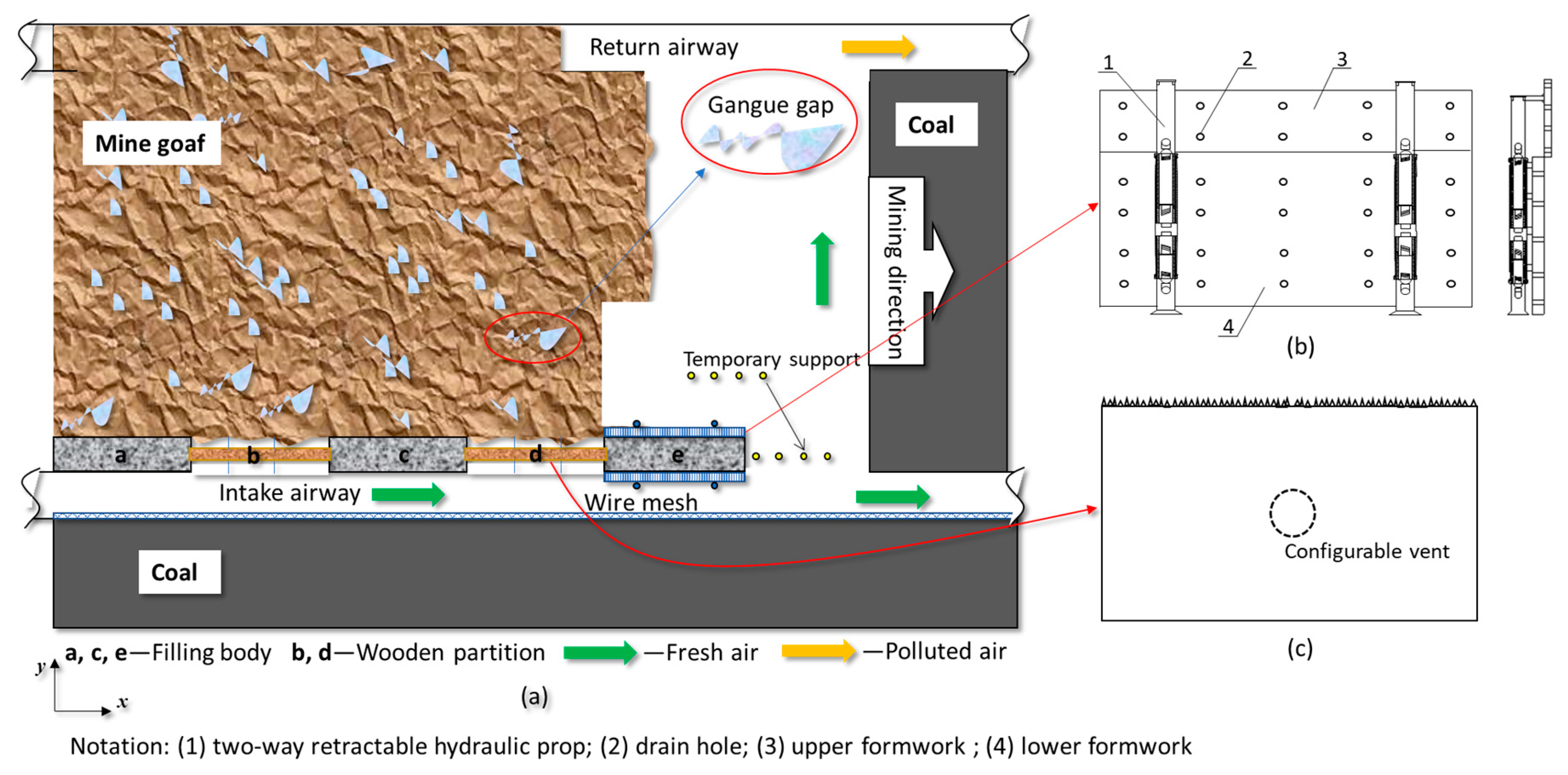
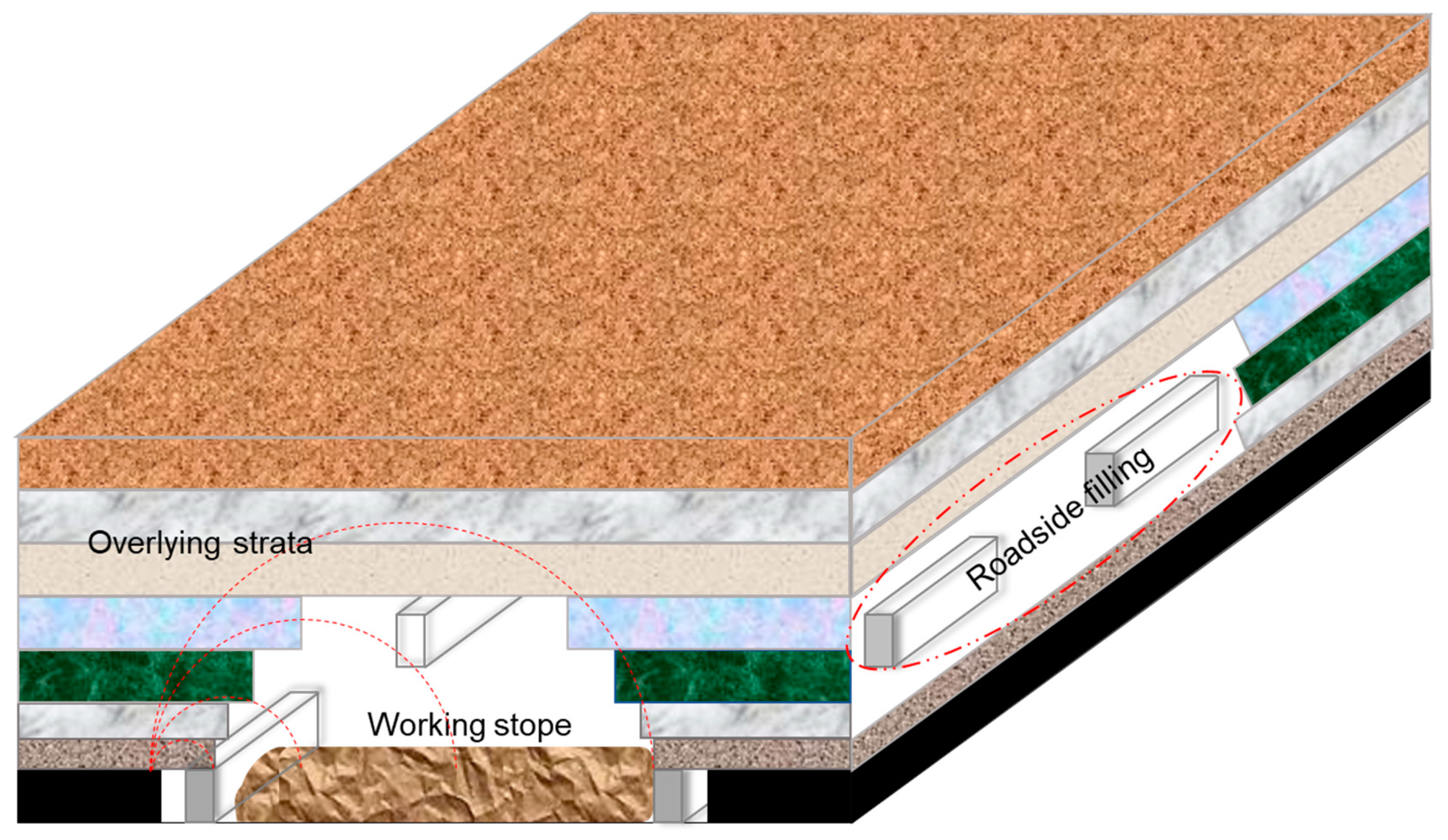
3.2. Segmented Roadside Plugging-Filling Mining Method (SRPF)
3.3. Mining Process with New Device
4. Mechanical Mechanism of Overlying Rock
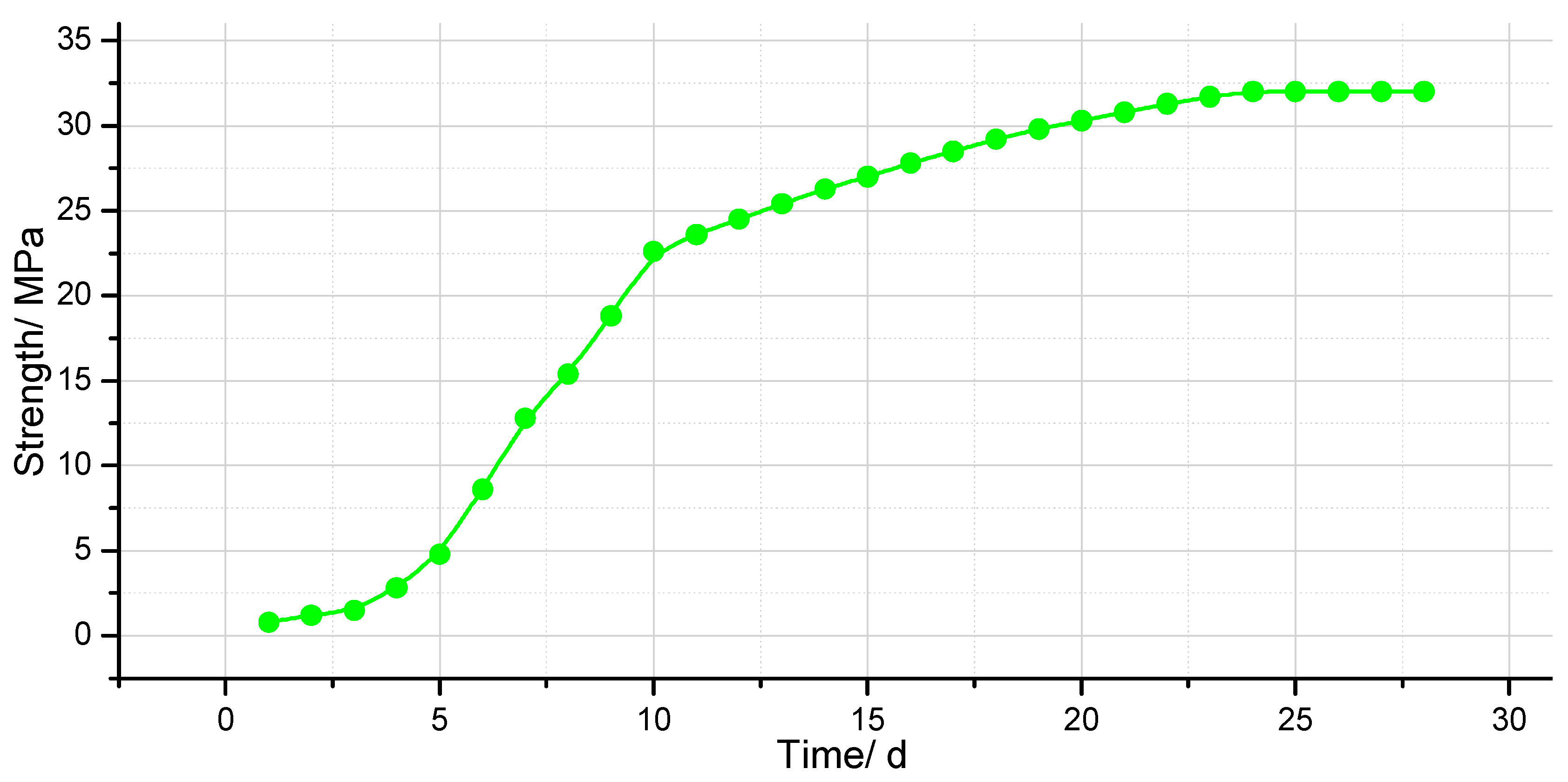
4.1. CSW Mechanical Strength Analysis at Different Stages
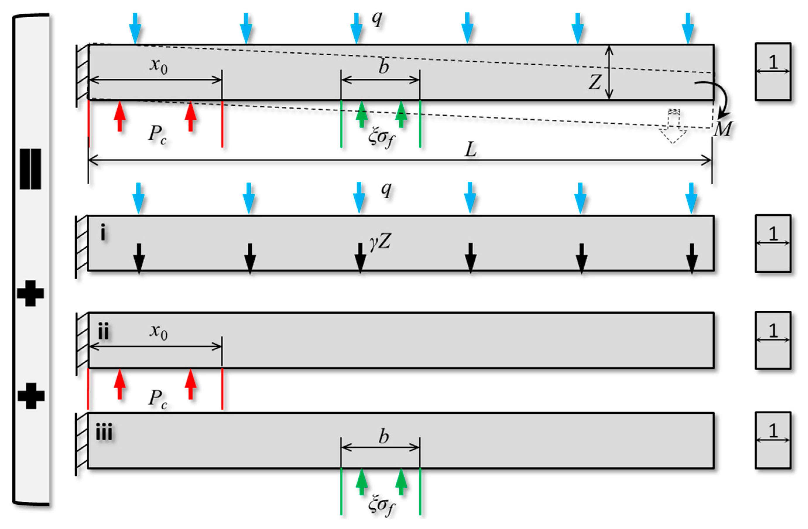
4.2. SDR Mechanical Analysis
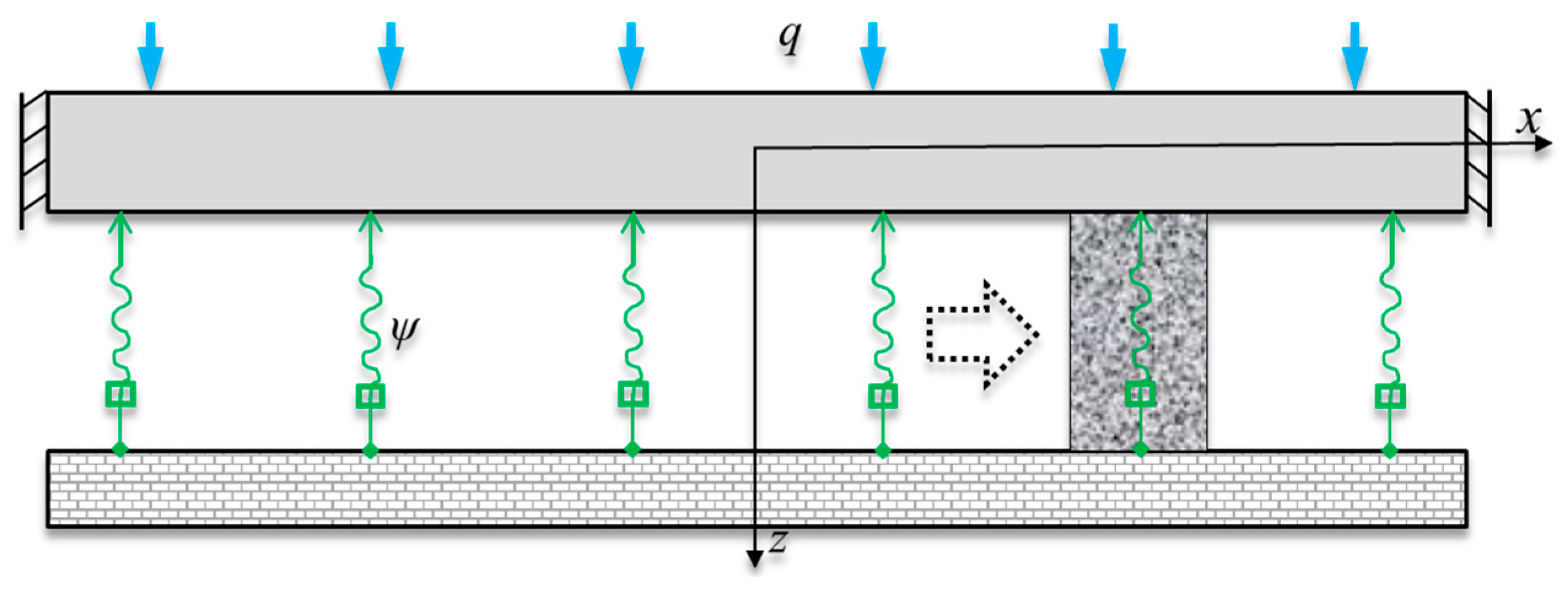
4.3. Segmented Roof Deformation
5. Field Application
5.1. Calculation Results
5.2. Deformation and Bearing Capacity Monitoring of Roadway and Filling Body
6. Discussion
7. Conclusions
Author Contributions
Funding
Conflicts of Interest
Notation
| GER | gob-side entry retaining | SRPF | segmented roadside plugging-filling |
| ξ | filling coefficient | n | number of filling bodies |
| m | number of plugging wooden partitions | lb | unit filling body length |
| lw | unit plugging wooden partition length | q | uniform load on overlying strata |
| x0 | action range of coal body | b | filling width |
| z | rock beam thickness | Pc | coal strength |
| σf | initial strength of filling body | L | rotating deformation length of rock beam |
| wmax, wmax-i, wmax-ii, wmax-iii | maximum deflection for models i, ii, and iii | ||
| E | elastic modulus of rock | I | polar moment of inertia |
| C | coal cohesion | φ | internal friction angle |
| d | roadway width | Lz | immediate roof length |
| δ | crushing expansion | h | mining height |
| h1 | immediate roof thickness | h2 | main roof thickness |
| qN | later arch load | P2 | gangue support strength |
| LXD | hanging roof length | σfm | later strength of filling body |
| k | stress concentration factor | Ef | elastic modulus of filling body |
| Hf | filling height | ν | Poisson’s ratio of rock beam |
| 2l | segmented hanging roof length | Dr | roadway length |
| ψ | equivalent elastic coefficient | w0 | maximum deflection |
| σx, σy, σz, τxy, τzx, τzy | stress components | ||
| εx, εy, γxy | strain components | ||
References
- Lin, H.L.; Shi, Y.K. Research on walling-up with concrete block technology of gob-side entry retaining based on fully mechanized face in medium-thickness coal seam. Appl. Mech. Mater. 2012, 121–126, 2878–2882. [Google Scholar] [CrossRef]
- Feng, G.R.; Wang, P.F.; Chugh, Y.P.; Zhao, J.L.; Wang, Z.Q.; Zhang, Z.P. A coal burst mitigation strategy for tailgate during deep mining of inclined longwall top coal caving panels at huafeng coal mine. Shock Vib. 2018, 2018, 1–18. [Google Scholar] [CrossRef]
- Li, Z.L.; He, X.Q.; Dou, L.M.; Song, D.Z.; Wang, G.F. Numerical investigation of load shedding and rock burst reduction effects of top-coal caving mining in thick coal seams. Int. J. Rock Mech. Min. Sci. 2018, 110, 266–278. [Google Scholar] [CrossRef]
- Zhang, D.S.; Miao, X.X.; Feng, G.M.; Song, Z.Q. Testing study on deformation features of surrounding rocks of gob-side entry retaining in fully-mechanized coal face with top-coal caving. J. China Univ. Min. Technol. 2003, 32, 232–235. [Google Scholar]
- Gong, P.; Ma, Z.G.; Ni, X.Y.; Zhang, R.R. Floor heave mechanism of gob-side entry retaining with fully-mechanized backfilling mining. Energies 2017, 10, 2085. [Google Scholar] [CrossRef]
- Jiang, L.S.; Zhang, P.P.; Chen, L.J.; Hao, Z.; Sainoki, A.; Mitri, H.S.; Wang, Q.B. Numerical approach for goaf-side entry layout and yield pillar design in fractured ground conditions. Rock Mech. Rock Eng. 2017, 50, 3049–3071. [Google Scholar] [CrossRef]
- Yang, H.Y.; Cao, S.G.; Wang, S.Q.; Fan, Y.C.; Wang, S.; Chen, X.Z. Adaptation assessment of gob-side entry retaining based on geological factors. Eng. Geol. 2016, 209, 143–151. [Google Scholar] [CrossRef]
- Liu, Y.K.; Zhou, F.B.; Liu, L.; Liu, C.; Hu, S.Y. An experimental and numerical investigation on the deformation of overlying coal seams above double-seam extraction for controlling coal mine methane emissions. Int. J. Coal Geol. 2011, 87, 139–149. [Google Scholar]
- Wen, Z.J.; Jiang, Y.J.; Song, Z.Q.; Tang, J.Q. Study on mechanical model and surrounding rock catastrophe system of Gob-side retaining entry. J. Hunan Univ. Sci. Technol. 2011, 26, 12–16. [Google Scholar]
- Tan, Y.L. Mining Pressure and Strata Control; Coal Industry Press: Beijing, China, 2008. [Google Scholar]
- Yu, B.; Zhang, Z.Y.; Kuang, T.J.; Liu, J.R. Stress changes and deformation monitoring of longwall coal pillars located in weak ground. Rock Mech. Rock Eng. 2016, 49, 3293–3305. [Google Scholar] [CrossRef]
- Yu, Y.; Deng, K.Z.; Luo, Y.; Chen, S.E.; Zhuang, H.F. An improved method for long-term stability evaluation of strip mining and pillar design. Int. J. Rock Mech. Min. Sci. 2018, 107, 25–30. [Google Scholar] [CrossRef]
- Yin, D.W.; Chen, S.J.; Liu, X.Q.; Ma, H.F. Effect of joint angle in coal on failure mechanical behaviour of roof rock-coal combined body. Q. J. Eng. Geol. Hydrogeol. 2018, 51, 202–209. [Google Scholar] [CrossRef]
- Shuang, H.Q.; Li, S.G.; Chen, G.F.; Xiao, P.; Shen, L.C.; Song, K.L. Influence mechanism of main roof height on surrounding rock stability of gob-side entry driving. Teh. Vjesn. 2018, 25, 492–501. [Google Scholar]
- Chen, Y.; Bai, J.B.; Zhu, T.L.; Yan, S.; Zhao, S.H.; Li, X.C. Mechanisms of roadside support in gob-side entry retaining and its application. Rock Soil Mech. 2012, 33, 1427–1432. [Google Scholar]
- Wang, A.L.; Ma, L.Q.; Wang, Z.W.; Zhang, D.S.; Li, K.; Zhang, Y.; Yi, X.J. Soil and water conservation in mining area based on ground surface subsidence control: Development of a high-water swelling material and its application in backfilling mining. Environ. Earth Sci. 2016, 75, 779. [Google Scholar] [CrossRef]
- Wu, D.; Yang, B.G.; Liu, Y.C. Transportability and pressure drop of fresh cemented coal gangue-fly ash backfill (CGFB) slurry in pipe loop. Powder Technol. 2015, 284, 218–224. [Google Scholar] [CrossRef]
- Gong, P.; Ma, Z.G.; Ni, X.Y.; Zhang, R.R. An experimental investigation on the mechanical properties of gangue concrete as a roadside support body material for backfilling gob-side entry retaining. Adv. Mater. Sci. Eng. 2017, 2018, 1–11. [Google Scholar]
- Huang, P.; Spearing, A.J.S.; Feng, J.; Jessu, K.V.; Guo, S. Effects of solid backfilling on overburden strata movement in shallow depth longwall coal mines in west china. J. Geophys. Eng. 2018, 15, 2194–2208. [Google Scholar] [CrossRef]
- Li, B.Y.; Ju, F. An experimental investigation into the compaction characteristic of granulated gangue backfilling materials modified with binders. Environ. Earth Sci. 2018, 77, 284. [Google Scholar] [CrossRef]
- Zhang, G.C.; Tan, Y.L.; Liang, S.J.; Jia, H.G. Numerical estimation of suitable gob-side filling wall width in a highly gassy longwall mining panel. Int. J. Geomech. 2018, 18, 1–15. [Google Scholar] [CrossRef]
- Zhang, S.; Wang, X.F.; Fan, G.W.; Zhang, D.S.; Cui, J.J. Pillar size optimization design of isolated island panel gob-side entry driving in deep inclined coal seam—case study of Pingmei No. 6 coal seam. J. Geophys. Eng. 2018, 15, 816–828. [Google Scholar] [CrossRef]
- Li, Z.L.; Dou, L.M.; Cai, W.; Wang, G.F.; Ding, Y.L.; Kong, Y. Roadway stagger layout for effective control of gob-side rock bursts in the longwall mining of a thick coal seam. Rock Mech. Rock Eng. 2016, 49, 621–629. [Google Scholar] [CrossRef]
- Sun, C.D.; Zhang, D.S.; Wang, X.F.; Zhou, R. Large-size test on creep characteristics of high-water material for filling body beside roadway. J. Min. Saf. Eng. 2012, 29, 487–491. [Google Scholar]
- Wang, X.F.; Zhang, D.S.; Sun, C.D.; Wang, Y. Surface subsidence control during bag filling mining of super high-water content material in the Handan mining area. Int. J. Oil Gas Coal Technol. 2016, 13, 87–102. [Google Scholar] [CrossRef]
- Tan, Y.L.; Yu, F.H.; Ning, J.G.; Zhao, T.B. Adaptability theory of roadside support in gob-side entry retaining and its supporting design. J. China Coal Soc. 2015, 41, 376–382. [Google Scholar]
- Tan, Y.L.; Yu, F.H.; Ning, J.G.; Zhao, T.B. Design and construction of entry retaining wall along a gob side under hard roof stratum. Int. J. Rock Mech. Min. Sci. 2015, 77, 115–121. [Google Scholar] [CrossRef]
- Liu, X.S.; Ning, J.G.; Tan, Y.L.; Xu, Q.; Fan, D.Y. Coordinated supporting method of gob-side entry retaining in coal mines and a case study with hard roof. Geomech. Eng. 2018, 15, 1173–1182. [Google Scholar]
- Bai, J.B.; Shen, W.L.; Guo, G.L.; Wang, X.Y.; Yu, Y. Roof deformation, failure characteristics, and preventive techniques of gob-side entry driving heading adjacent to the advancing working face. Rock Mech. Rock Eng. 2015, 48, 2447–2458. [Google Scholar] [CrossRef]
- Zhang, Z.Z.; Bai, J.B.; Chen, Y.; Yan, S. An innovative approach for gob-side entry retaining in highly gassy fully-mechanized longwall top-coal caving. Int. J. Rock Mech. Min. Sci. 2015, 80, 1–11. [Google Scholar] [CrossRef]
- He, M.C.; Gao, Y.B.; Yang, J.; Gong, W.L. An innovative approach for gob-side entry retaining in thick coal seam longwall mining. Energies 2017, 10, 1785. [Google Scholar] [CrossRef]
- Wang, Q.; He, M.C.; Yang, J.; Gao, H.K.; Jiang, B.; Yu, H.C. Study of a no-pillar mining technique with automatically formed gob-side entry retaining for longwall mining in coal mines. Int. J. Rock Mech. Min. Sci. 2018, 110, 1–8. [Google Scholar] [CrossRef]
- Ning, J.G.; Wang, J.; Bu, T.T.; Hu, S.C.; Liu, X.S. An Innovative Support Structure for Gob-Side Entry Retention in Steep Coal Seam Mining. Minerals 2017, 7, 75. [Google Scholar] [CrossRef]
- Mu, W.Q. Research and application of gob-side entry retaining mining technology based on deformation mechanism of roadside backfill. Master’s Thesis, Shandong University of Science and Technology, Qing Dao, China, 2017. [Google Scholar]
- Li, H.M. Control design of roof rocks for gob-side entry. Chin. J. Rock Mech. Eng. 2000, 19, 651–654. [Google Scholar]
- Han, C.L.; Zhang, N.; Li, B.Y.; Si, G.Y.; Zheng, X.G. Pressure relief and structure stability mechanism of hard roof for gob-side entry retaining. J. Cent. South Univ. 2015, 22, 4445–4455. [Google Scholar] [CrossRef]
- Yin, D.W.; Meng, X.X.; Zhang, Z.Y.; Liu, B.C. Gob-side entry retaining formed by roof cutting without roadside support. Int. J. Oil Gas Coal Technol. 2018, 18, 467–484. [Google Scholar] [CrossRef]
- Wen, Z.J.; Jing, S.L.; Song, Z.Q.; Jiang, Y.J.; Tang, J.Q. Study on coal face spatial structure model and control related dynamic disasters. Chin. J. Coal Sci. Technol. 2019, 47, 52–61. [Google Scholar]
- Wu, J.L. Mechanics of Elasticity, 3rd ed.; Higher Education Press: Beijing, China, 2016; pp. 137–159. [Google Scholar]
- Feng, F.; Li, D.Y.; Li, X.B.; Guo, Z.P.; Wang, S.F.; Chen, Y. Novel underhand cut-and-fill stoping method and mechanical analysis of overlying backfill. Int. J. Geomech. 2018, 17, 1–15. [Google Scholar] [CrossRef]
- Gupta, A.K.; Paul, B. Comparative analysis of different materials to be used for backfilling in underground mine voids with a particular reference to hydraulic stowing. Int. J. Oil Gas Coal Technol. 2017, 15, 425–434. [Google Scholar] [CrossRef]
- Ning, J.G.; Ma, P.F.; Liu, X.S.; Zhao, J.; Liu, W. Supporting mechanism of ‘yielding-supporting’ beside roadway maintained along the goaf under hard rocks. J. Min. Saf. Eng. 2013, 30, 369–374. [Google Scholar]


| Parameters | LZ/m | L/m | q/MPa | Pc/MPa | I/m4 | x0/m |
| Value | 8.5 | 22 | 13.6 | 1.3 | 158.88 | 1.21 |
| Parameters | E/GPa | qn/MPa | γ/N/m | LXD/m | C/MPa | δ |
| Value | 16.7 | 0.99 | 2600 | 13.5 | 2.4 | 1.25 |
© 2019 by the authors. Licensee MDPI, Basel, Switzerland. This article is an open access article distributed under the terms and conditions of the Creative Commons Attribution (CC BY) license (http://creativecommons.org/licenses/by/4.0/).
Share and Cite
Mu, W.; Li, L.; Guo, Z.; Du, Z.; Wang, S. Novel Segmented Roadside Plugging-Filling Mining Method and Overlying Rock Mechanical Mechanism Analyses. Energies 2019, 12, 2073. https://doi.org/10.3390/en12112073
Mu W, Li L, Guo Z, Du Z, Wang S. Novel Segmented Roadside Plugging-Filling Mining Method and Overlying Rock Mechanical Mechanism Analyses. Energies. 2019; 12(11):2073. https://doi.org/10.3390/en12112073
Chicago/Turabian StyleMu, Wenqiang, Lianchong Li, Zhongping Guo, Zhaowen Du, and Sixu Wang. 2019. "Novel Segmented Roadside Plugging-Filling Mining Method and Overlying Rock Mechanical Mechanism Analyses" Energies 12, no. 11: 2073. https://doi.org/10.3390/en12112073
APA StyleMu, W., Li, L., Guo, Z., Du, Z., & Wang, S. (2019). Novel Segmented Roadside Plugging-Filling Mining Method and Overlying Rock Mechanical Mechanism Analyses. Energies, 12(11), 2073. https://doi.org/10.3390/en12112073